1
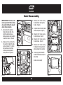
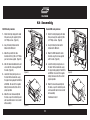
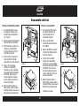
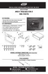
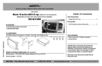
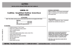
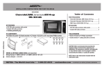
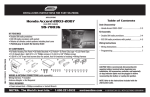
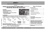
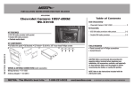
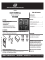
INSTALLATION INSTRUCTIONS FOR PART 99-5830B
APPLICATIONS
Table of Contents
Ford F-150 2013-up
With factory 4.2 inch LCD screen
Dash Disassembly
99-5830B
– Ford F-150 2013-up ............................................ 2
Kit Assembly
KIT FEATURES
• ISO DIN radio provision with pocket
• Double DIN radio provision
• Painted Matte Black
• Integrated button and LCD climate control panel
• Integrated hazard button and passenger airbag light
– ISO DIN radio provision with pocket...................... 3
– Double DIN radio provision ................................... 3
– Color adjustment .................................................. 4
KIT COMPONENTS
• A) Radio trim panel • B) Radio brackets • C) Pocket • D) (4) #8 x 3/8” Phillips screws for pocket
• E) (4) #8 x 3/8” Phillips screws for OE display to housing
REV. 8/16/2013 INST99-5830B
A
B
C
D
E
TOOLS REQUIRED
• Panel removal tool • Phillips screwdriver
• Socket Wrench • Torx screwdrivers
CAUTION: Metra recommends disconnecting the
negative battery terminal before beginning any
installation. All accessories, switches, and especially
air bag indicator lights must be plugged in before
reconnecting the battery or cycling the ignition.
WIRING & ANTENNA CONNECTIONS (sold separately)
Wiring Harness: • AX-ADBOX1 Interface • AX-ADBOX2 Interface • AX-ADFD02 Harness
Antenna Adapter: • 40-EU10 Multi-App Antenna Adapter
METRA. The World’s best kits.™
1-800-221-0932
NOTE: Refer to the instructions included with the
aftermarket radio.
metraonline.com
© COPYRIGHT 2004-2011 METRA ELECTRONICS CORPORATION
99-5830
Dash Disassembly
IMPORTANT NOTE: The factory radio
must be powered off before starting
disassembly. Omitting this step will
disable the menu function.
3. Remove (4) 9/32” screws securing
the radio/climate control panel to
the dash. (Figure C)
4. Unclip and remove the factory radio/
climate control panel. (Figure C)
1. Open and lower the glove box.
Remove three 8mm bolts, from
inside the glove box facing up,
holding passenger airbag assembly
to dash and remove it. (Figure A)
2. Remove one 7mm screw from the
trim panel to the right of the radio,
unclip and remove it. The driver’s
side panel does not need to be
removed, just unclipped so the
center panel is free. (Figure B)
5. Remove (4) 9/32” screws securing
the factory display. (Figure D)
6. Remove (4) 9/32” screws securing
the radio chassis. (Figure D)
7. Remove (4) 9/32” screws securing
the display to the display brackets
and keep display for kit assembly.
(Figure B)
8. Unsnap, unplug, and remove the
traction control button and save for
kit assembly.
(Figure D)
Continue to kit assembly
(Figure A)
(Figure E)
(Figure C)
2
99-5830
Kit Assembly
ISO DIN radio provision
Double DIN radio provision
1. Attach the factory display to the radio
trim panel using the supplied (4) #8 x
3/8” Phillips screws. (Figure A)
1. Attach the factory display to the radio
trim panel using the supplied (4) #8 x
3/8” Phillips screws. (Figure A)
2. Snap the factory traction control
button into the Metra kit.
2. Snap the factory traction control
button into the Metra kit.
3. Mount the pocket to the radio
brackets with the (4) #8 x 3/8” Phillips
pan head screws supplied. (Figure B)
3. Mount the DDIN radio to the radio
brackets using the screws supplied
with the radio. (Figure B)
4. Slide the radio into radio brackets and
secure with the screws supplied with
the radio. (Figure B)
4. Locate the factory wiring harness in
the dash. Metra recommends using
the proper mating adapter from Metra
or AXXESS. Re-connect the negative
battery terminal and test the unit for
proper operation.
5. Locate the factory wiring harness in
the dash. Metra recommends using
the proper mating adapter from Metra
or AXXESS. Re-connect the negative
battery terminal and test the unit for
proper operation.
6. Mount the new radio assembly into
the dash, snap-in the radio trim panel,
and reassemble dash in reverse order
of disassembly.
(Figure A)
(Figure A)
5. Mount the new radio assembly into
the dash, snap-in the radio trim panel,
and reassemble dash in reverse order
of disassembly.
Continued on back
(Figure B)
(Figure B)
3
INSTALLATION INSTRUCTIONS FOR PART 99-5830B
Installation Instructions
Color Adjustment:
1. Press and hold the bottom left hot key for 5-seconds until
the A/C icon begins to blink.
2. Press and hold the MAX button to increase Red.
3. Press and hold the A/C button to decrease Red.
+
-
4. Press and hold the Recirculation button
to increase Green.
5. Press and hold the Mode button to decrease Green.
6. Press and hold the Rear Defrost button to increase Blue.
7. Press and hold the Front Defrost button to decrease Blue.
Red
Up
Down
Left
Right
Green
Blue
8. After you choose your color stop pressing the buttons
and after 5-seconds the color chosen will stay and the display
will stop blinking.
Clock Adjustment:
1. Press the menu button to access on-screen menu.
2. Scroll to “clock” in menu.
3. Adjust clock settings.
REV. 8/16/2013 INST99-5830B
KNOWLEDGE IS POWER
Enhance your installation and fabrication skills by
enrolling in the most recognized and respected
mobile electronics school in our industry.
Log onto www.installerinstitute.com or call
800-354-6782 for more information and take steps
toward a better tomorrow.
For use with SYNC and
factory screen menus
METRA. The World’s best kits.™
Press and hold 5-seconds to
enter LCD color change mode
Enter
1-800-221-0932
metraonline.com
Metra recommends MECP
certified technicians
© COPYRIGHT 2004-2011 METRA ELECTRONICS CORPORATION
INSTRUCCIONES DE INSTALACIÓN PARA LA PIEZA 99-5830B
APLICACIONES
Indice
Ford F-150 2013 y más recientes
Con pantalla de fábrica LCD de 4.2 pulgadas
Desmontaje del tablero
99-5830B
– Ford F-150 2013 y más recientes ........................ 2
Ensamble del kit
CArACtEríStICAS dEL kIt
• Provisión de radio ISO DIN con bolsillo
• Provisión de radio doble DIN
• Pintura negro mate
• Botón integrado y panel de control de clima LCD
• Botón integrado de luces intermitentes y foco de la bolsa
de aire del pasajero
– Provisión de radio ISO DIN con bolsillo ................. 3
– Provisión de radio doble DIN................................. 3
– Ajuste de color ..................................................... 4
REV. 8/16/2013 INST99-5830B
COmPONENtES dEL kIt
• A) Panel de moldura para radio • B) Soportes para radio • C) Bolsillo • D) (4) Tornillos Phillips #8 de 3/8”
para la bolsillo • E) (4) Tornillos Phillips #8 de 3/8” para la pantalla OE a la carcasa
A
B
C
D
E
HErrAmIENtAS rEquErIdAS
• Herramienta para quitar paneles • Destornillador
Phillips • Llave para dados • Destornilladores Torx
PRECAUCIÓN: Metra recomienda desconectar el terminal
negativo de la batería antes de comenzar cualquier
instalación. Todos los accesorios, interruptores y,
especialmente, las luces indicadoras de airbag deben
estar enchufados antes de volver a conectar la batería o
comenzar el ciclo de ignición.
CABLEAdO Y CONEXIONES dE ANtENA (se venden por separado)
Arnés de cables: Interfase AX-ADBOX1 • Interfase AX-ADBOX2 • Arnés AX-ADFD02
Adaptador de antena: • Adaptador de antena 40-EU10 de aplicaciones múltiples
METRA. The World’s best kits.™
1-800-221-0932
NOTA: Remítase a las instrucciones incluidas con el
radio de postventa.
metraonline.com
© COPYRIGHT 2004-2011 METRA ELECTRONICS CORPORATION
99-5830
Desmontaje del tablero
NOTA IMPORTANTE: El radio de fábrica debe apagarse antes de iniciar
el desensamble. Omitir este paso
deshabilitará la función del menú.
1. Abra y baje la guantera. Quite los
tres pernos de 8 mm del interior de
la guantera orientados hacia arriba,
sosteniendo el ensamble de la bolsa
de aire del pasajero contra el tablero
y quítelo. (Figura A)
2. Quite un tornillo de 7 mm del
panel de la moldura a la derecha
del radio, desenganche y quite. El
panel del lado del conductor no
necesita quitarse, simplemente
desengancharse de manera que el
panel central quede libre. (Figura B)
3. Quite los (4) tornillos de 9/32” que
sujetan el radio/panel de control de
clima al tablero. (Figura C)
4. Desenganche y quite el panel de
radio de fábrica/control del clima.
(Figura C)
5. Quite los (4) tornillos de 9/32”
que sujetan la pantalla de fábrica.
(Figura D)
(Figura B)
6. Quite los (4) tornillos de 9/32” que
sujetan el chasís del radio. (Figura D)
7. Quite los (4) tornillos de 9/32” que
sujetan la pantalla a los soportes
de la pantalla y conserve la pantalla
para el ensamble del kit.
(Figura D)
8. Suelte a presión, desconecte y quite
el botón de control de tracción y
guárdelo para el ensamble del kit.
Continuará al ensamble del kit
(Figura A)
(Figura E)
(Figura C)
2
99-5830
Ensamble del kit
Provisión de radio ISO DIN con bolsillo
Provisión de radio doble DIN
1. Una la pantalla de fábrica al panel
de la moldura del radio con los (4)
tornillos Phillips suministrados #8 x
3/8”. (Figura A)
2. Coloque a presión el botón de control de
tracción de fábrica en el kit de Metra.
3. Monte la bolsillo en los soportes del
radio con los (4) tornillos Phillips
de cabeza troncocónica #8 de 3/8”
suministrados. (Figura B)
4. Deslice el radio en los soportes del
radio y sujételo con los tornillos
suministrados con el radio. (Figura B)
5. Ubique el arnés de cableado
de fábrica en el tablero. Metra
recomienda el uso de un adaptador
adecuado de acoplamiento de Metra
o de AXXESS. Vuelva a conectar
la terminal negativa de la batería y
pruebe la unidad para verificar que
funcione correctamente.
6. Monte el conjunto del radio en el
tablero, coloque a presión el panel de
la moldura del radio y vuelva a armar el
tablero al revés de como lo desarmó.
1. Una la pantalla de fábrica al panel
de la moldura del radio con los
(4) tornillos Phillips #8 X 3/8”
suministrados. (Figura A)
2. Coloque a presión el botón
de control de tracción de fábrica en
el kit de Metra.
3. Monte el radio DDIN en los soportes
de radio con los tornillos que vienen
con el radio. (Figura B)
4. Ubique el arnés de cableado
de fábrica en el tablero. Metra
recomienda el uso de un adaptador
adecuado de acoplamiento de Metra
o de AXXESS. Vuelva a conectar
la terminal negativa de la batería y
pruebe la unidad para verificar que
funcione correctamente.
(Figura A)
(Figura A)
5. Monte el conjunto del radio en el
tablero, coloque a presión el panel de
la moldura del radio y vuelva a armar el
tablero al revés de como lo desarmó.
Continúa en la espalda
(Figura B)
(Figura B)
3
INSTRUCCIONES DE INSTALACIÓN PARA LA PIEZA 99-5830B
Installation Instructions
Ajuste del color:
1. Presione y mantenga presionada la tecla rápida izquierda
de abajo durante 5 segundos hasta que el ícono del aire
acondicionado empiece a parpadear.
2. Presione y mantenga presionado el botón MAX para
aumentar el rojo.
+
-
3. Presione y mantenga presionado el botón del aire
acondicionado para disminuir el rojo.
4. Presione y mantenga presionado el botón de
recirculación para aumentar el verde.
5. Presione y mantenga presionado el botón de modo para
disminuir el verde.
Rojo
Arriba
Verticales
Derecha
Izquierda
Verde
Azul
6. Presione y mantenga presionado el botón de descongelador
trasero para aumentar el azul.
7. Presione y mantenga presionado el botón de descongelador
delantero para disminuir el azul.
8. Después de elegir el color deseado, deje de presionar los
botones y después de 5 segundos, el color seleccionado se
quedará y la pantalla dejará de parpadear.
Ajuste del reloj:
1. Presione el botón de menú para acceder al menú en pantalla.
2. Desplácese a “clock” (reloj) en el menú.
3. Ajuste el reloj.
EL CONOCIMIENTO ES PODER
REV. 8/16/2013 INST99-5830B
sus habilidades deIS
instalación
y
KMejore
NOWLEDGE
POWER
Enhance
your installation
and fabrication
skills by
fabricación
inscribiéndose
en la escuela
de
enrolling in the most recognized and respected
dispositivos
electrónicos
móviles
más reconocida
mobile
electronics
school in our
industry.
Log
onto www.installerinstitute.com
or Regístrese
call
y respetada
de nuestra industria.
en
800-354-6782 for more information and take steps
www.installerinstitute.com o llame al
toward a better tomorrow.
800-354-6782 para obtener más información y
avance hacia un futuro mejor.
Para usarse con los menús de
SYNC y de la pantalla de fábrica.
Presione y mantenga presionado durante 5 segundos
para entrar al modo de cambio de color de LCD
Aceptar
METRA. The World’s best kits.™
1-800-221-0932
metraonline.com
Metra recomienda técnicos
con certificación del Programa
de Certificación en Electrónica
Móvil (Mobile Electronics
Certification Program, MECP).
© COPYRIGHT 2004-2011 METRA ELECTRONICS CORPORATION