1
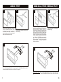
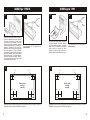
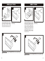
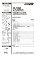
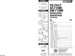
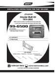
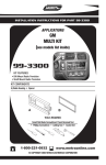
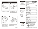
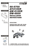
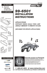
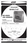
KIT FEATURES
ALL VEHICLES
Shaft, DIN and
ISO-DIN unit
provisions
4
Fig. C
Fig. A
Pocket
provisions
Fig. B
99-7892
INSTALLATION
INSTRUCTIONS
KIT COMPONENTS
2-SHAFT HEAD UNITS: Snap the Faceplate into the Radio Housing. Slide the aftermarket
head unit into the kit and secure with shaft nuts. (see Fig. A)
Radio Housing
DIN HEAD UNITS: Slide the DIN cage into the kit and secure by bending the metal locking tabs
down. Slide the aftermarket head unit into the cage until secure. (see Fig. B)
ISO-DIN HEAD UNITS: Slide the ISO-DIN Brackets onto the sides of the Rear Support
Bracket. Cut and remove the shaft supports from the Faceplate and snap into the Radio
Housing. Slide the aftermarket head unit into the Housing, align the holes in the unit with the
holes in the ISO-DIN Brackets and mount with the screws supplied with the unit. (see Fig. C)
5
A
6
Rear Support
Bracket
B
Fig. A
C
ISO-DIN
Brackets
D
Faceplate
A) Strip wire ends back ½"
B) Twist ends together
C) Solder
D) Tape
(2) Phillips
Screws
Fig. B
Locate the factory wiring harness in the
dash. Metra recommends using the
proper mating adaptor and making
connections as shown. (Isolate and
individually tape off the ends of any
unused wires to prevent electrical short
circuit).
11
ACCORD 1990-93, INTEGRA, ODYSSEY,
OASIS: Re-connect the battery terminal and test
the unit for proper operation. Snap the head
unit/kit assembly into the sub-dash.
LEGEND, TL, VIGOR: Re-connect the battery
terminal and test the unit for proper operation.
Snap the head unit/kit assembly into the factory
trim bezel. Mount the bezel to the dash with those
screws previously removed in step #1. (see Fig. A)
ACCORD 1994-97, CL: Re-connect the battery
terminal and test the unit for proper operation.
Slide the head unit/kit assembly into the sub-dash
and mount the Rear Support Bracket to the rear
support provision with (2) hex-head bolts
previously removed. (see Fig. B)
rev. 250701
APPLICATIONS
CAR
PAGE
ACURA
CL 1997-99................................................................. 1
Integra 1990-93.......................................................... 2
Integra 1994-00.......................................................... 3
Legend 1990................................................................4
Legend 1991-96.......................................................... 5
TL 1996-98..................................................................6
Vigor 1992-94............................................................. 7
HONDA
Accord 1990-93........................................................... 8
Accord 1994-97........................................................... 9
Odyssey 1995-98.........................................................10
ISUZU
Oasis 1996-99............................................................. 10
TOOLS REQUIRED
Phillips screwdriver
Cutting tool
1-800-221-0932
Socket wrench
www.metraonline.com
© COPYRIGHT 2001 METRA ELECTRONICS CORPORATION
ACURA CL 1997-99
1
Disconnect the negative battery terminal to
prevent an accidental short circuit. Unclip
the radio trim bezel and disconnect the clock
and climate control wiring. Remove (2)
8mm hex-head screws securing the factory
head unit and disconnect the wiring.
2
Cut and remove the SIDE clips from the
Radio Housing.
HONDA Odyssey 1995-98 / ISUZU Oasis 1996-99
1
Disconnect the negative battery terminal to
prevent an accidental short circuit. Remove (2)
8mm screws under the glove box. Remove (1)
Phillips screw on the glove box arm and remove
the box. Remove (2) Phillips screws exposed in
the glove box cavity. Remove (2) Phillips screws
below the storage box door (under the ashtray).
Remove (2) screws from the left side of the dash
console. Remove (1) Phillips screw from the coin
tray. Remove (1) Phillips screw under the
ignition. Remove (4) Phillips screws securing the
factory cupholder. Remove (2) 8mm hex-head
screws from the rear support bracket and
disconnect the wiring.
2
Cut and remove the TOP clips from the
Radio Housing.
3
3
Mount the Rear Support Bracket to the back of the pocket with (2) Phillips Screws supplied.
Skip to the Installation Instructions for ALL VEHICLES on Page #11.
ISO-DIN HEAD UNITS: Mount the Rear Support Bracket to the back of the pocket with (2)
Phillips Screws supplied. Skip to the Installation Instructions for ALL VEHICLES on Page
#11.
1
10
HONDA Accord 1994-97
1
1
Disconnect the negative battery terminal to prevent an accidental short circuit. Remove the
ashtray and (1) ¾" #8 Phillips screw exposed. Open the storage compartment and remove (2)
#8 Phillips screws exposed. Remove the cupholder tray and (3) #8 Phillips screws inside. Lift
the center console out and remove (2) Phillips screws exposed at the base of the dash trim
bezel. Unclip the bezel and remove. Remove (2) hex-head screws securing the factory head
unit and disconnect the wiring.
2
Cut and remove the SIDE clips from the
Radio Housing.
9
ACURA Integra 1990-93
3
Mount the Rear Support Bracket to the back of
the pocket with (2) Phillips Screws supplied.
Skip to the Installation Instructions for ALL
VEHICLES on Page #11.
Disconnect the negative battery terminal to
prevent an accidental short circuit. Remove
(3) screws from each side of the center
console and remove the console. Remove
(2) screws securing the factory head unit to
the sub-dash support bracket. Slide the
head unit/pocket assembly out and
disconnect the wiring.
2
Cut and remove the TOP clips from the
Radio Housing.
3
ISO-DIN HEAD UNITS: Mount the Rear Support Bracket to the back of the pocket with (2)
Phillips Screws supplied. Skip to the Installation Instructions for ALL VEHICLES on Page
#11.
2
ACURA Integra 1994-00
1
Disconnect the negative battery terminal to
prevent an accidental short circuit. Remove
the cover cap located under the emergency
brake and remove (2) screws exposed.
Remove (2) screws from the rear corners of
the lower dash trim bezel and remove.
Remove the ashtray and (2) screws
exposed. Unsnap the ashtray housing and
disconnect the cigarette lighter harness.
Remove the gear shifter knob and unsnap
the shifter trim. Remove (2) screws below
the radio opening and remove the upper
dash trim bezel. Remove (2) 8mm screws
securing the factory head unit and
disconnect the wiring.
2
Cut and remove the TOP clips from the
Radio Housing.
3
ISO-DIN HEAD UNITS: Mount the Rear Support Bracket to the back of the pocket with (2)
Phillips Screws supplied. Skip to the Installation Instructions for ALL VEHICLES on Page
#11.
3
HONDA Accord 1990-93
1
Disconnect the negative battery terminal to
prevent an accidental short circuit. Remove
(4) screws from the lower portion of the
center console. Remove the gear shifter
knob and lift the console out. Remove the
ashtray and ashtray bracket. Remove (2)
screws from the bottom of the head unit
support, slide the unit out and disconnect the
wiring.
2
Cut and remove the TOP clips from the
Radio Housing.
3
ISO-DIN HEAD UNITS: Mount the Rear Support Bracket to the back of the pocket with (2)
Phillips Screws supplied. Skip to the Installation Instructions for ALL VEHICLES on Page
#11.
8
ACURA Vigor 1992-94
1
ACURA Legend 1990
2
Disconnect the negative battery terminal to
prevent an accidental short circuit. Remove
the access cap from the climate control
cluster and (1) screw exposed. Unclip the
cluster and remove (2) screws exposed.
Remove the ashtray and (2) Phillips screws
exposed. Remove the cover caps from
each front corner of the center console and
the screws exposed. Open the storage
compartment, lift up the carpet and remove
(2) screws exposed. Lift up on the center
console and remove. Unclip the radio trim
bezel and disconnect the wiring. Remove
(2) bolts from the back of the factory head
unit and disconnect the wiring.
1
Cut and remove the TOP clips from the
Radio Housing.
3
2
Disconnect the negative battery terminal to
prevent an accidental short circuit. Remove
(2) screws below the ashtray. Unclip the
dash trim bezel. Disconnect the cigarette
lighter wiring and remove the bezel.
Remove (2) bolts securing the rear of the
factory head unit and disconnect the wiring.
3
¼"
¼"
¼"
¾"
¾"
1¼"
1"
¼"
¾"
Factory radio
housing
opening
¾"
Factory radio
housing
opening
1"
1¼"
Modify the factory radio housing by trimming the shaded portions of the housing lip. Skip to the
Installation Instructions for ALL VEHICLES on Page #11.
7
Cut and remove the TOP clips from the
Radio Housing.
1¼"
1"
1"
1¼"
Modify the factory radio housing by trimming the shaded portions of the housing lip. Skip to the
Installation Instructions for ALL VEHICLES on Page #11.
4
ACURA Legend 1991-96
1
Disconnect the negative battery terminal to
prevent an accidental short circuit. Remove
(2) screws below the ashtray. Unclip the
dash trim bezel. Disconnect the cigarette
lighter wiring and remove the bezel.
Remove (2) bolts securing the rear of the
factory head unit and disconnect the wiring.
2
Cut and remove the TOP clips from the
Radio Housing.
ACURA TL 1996-98
1
Disconnect the negative battery terminal to
prevent an accidental short circuit. Using a
small screwdriver, unclip the perimeter of the
radio trim bezel. Disconnect the climate
control and rear defroster wiring and remove
the bezel. Remove (4) Phillips screws
securing the factory head unit/trim bezel
assembly.
Loosen (2) Phillips screws
securing the back of the head unit to the
metal housing and slide the unit out. (It is
NOT necessary to remove the screws
securing the metal housing to the bezel).
Disconnect the wiring.
2
Cut and remove the TOP clips from the
Radio Housing.
3
3
ISO-DIN HEAD UNITS: Mount the Rear Support Bracket to the back of the pocket with (2)
Phillips Screws supplied. Skip to the Installation Instructions for ALL VEHICLES on Page
#11.
5
ISO-DIN HEAD UNITS: Mount the Rear Support Bracket to the back of the pocket with (2)
Phillips Screws supplied. Skip to the Installation Instructions for ALL VEHICLES on Page
#11.
6