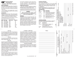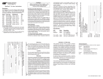
1
LED
Color
Power:
Yellow
DTE/DCE: Green
Yellow
DB9/232: Green
Fiber Link: Green
Green
Green
Function
Solid
Solid
Solid
Solid/Blink
Solid
Blink fast
Blink slow
Description
Power applied
DTE selected
DCE selected
Link / Data received
Link
Fiber loop-back is good
Error in fiber loop-back
Switches:
Description
Function
DB9 to DTE / DCE: Data Terminal / Data Communication
Fiber Loop-back: Loop-back / Normal
FlexPoint 232 Pin Assignments
5 SGND
RI 9
4 DTR
CTS 8
3 TD
RTS 7
2 RD
DSR 6
1 DCD
PIN
PIN SIGN AL
AB B R
D TE
DCE
1
D ata C arri er D etect
DCD
IN
OUT
2
Recei ved D ata
RD
IN
OUT
3
Transmi tted D ata
TD
OUT
IN
4
D ata Termi nal
D TR
OUT
IN
5
Si gnal Ground
SGND
-
-
6
D ata Set Ready
D SR
IN
OUT
7
Request To Send
RTS
OUT
IN
8
C lear To Send
C TS
IN
OUT
9
Ri ng Indi cator
RI
IN
OUT
When connecting the RS-232 cable to terminal
equipment such as a computer or controller, set the
switch to “DB9 to DCE” (down, factory setting). When
connecting to communication equipment such as a
modem or printer, set the switch to “DB9 to DTE” (up).
(Please refer to pin assignments for more detailed information)
“Fiber Loopback” Switch:
This switch will allow the entire fiber segment to be tested at
either of the FlexPoint 232 converters without having to set
switches on both units simultaneously. When the switch is
RS-232 Cable Specifications:
Gauge
Mutual Capacitance
Maximum distance
22 to 24 AWG
12 to 50 pF/ft.
15.2 m/50 ft.
Warning
Limitation of Warranty
The operating description in this Instruction Manual is
for use by qualified personnel only. To avoid electrical
shock, do not perform any servicing of this unit other
than that contained in the operating instructions, unless
you are qualified and certified to do so by Omnitron
Systems Technology, Inc.
The foregoing warranty shall not apply to defects resulting
from improper or inadequate use and/or maintenance
of the equipment by Buyer, Buyer-supplied equipment,
Buyer-supplied interfacing, unauthorized modifications
or tampering with equipment (including removal of
equipment cover by personnel not specifically authorized
and certified by Omnitron), or misuse, or operating
outside the environmental specification of the product
(including but not limited to voltage, ambient temperature,
radiation, unusual dust, etc.), or improper site preparation
or maintenance.
No other warranty is expressed or implied. Omnitron
specifically disclaims the implied warranties of
merchantability and fitness for any particular purpose.
Caution
All user-required operations can be performed without
opening the unit. Never attempt to open or remove the
cover or tamper with the unit.
Warranty
This product is warranted to the original purchaser against
defects in material and workmanship for a period of TWO
YEARS from the date of shipment. A LIFETIME warranty
may be obtained by the original purchaser by REGISTERING
this product with Omnitron within 90 days from the date of
shipment. TO REGISTER, COMPLETE AND MAIL OR FAX
THE REGISTRATION PORTION OF THIS INSTRUCTION
MANUAL TO THE INDICATED ADDRESS. Or you may
register your product on the internet at http://
www.omnitron-systems.com. During the warranty period,
Omnitron will, at its option, repair or replace a product which
is proven to be defective.
For warranty service, the product must be sent to an Omnitron
designated facility, at Buyer’s expense. Omnitron will pay the
shipping charge to return the product to Buyer’s designated
US address using Omnitron’s standard shipping method.
Exclusive Remedies
The remedies provided herein are the Buyer’s sole and
exclusive remedies. Omnitron shall not be liable for any
direct, indirect, special, incidental, or consequential
damages, whether based on contract, tort, or any legal
theory.
Technical Support:
For help with this product, contact our Tech. Support:
Phone:
(949) 250-6510
Fax:
(949) 250-6514
Address: Omnitron Systems Technology, Inc.
140 Technology Drive, #500
Irvine, CA 92618 USA
E-mail:
[email protected]
URL:
http://www.omnitron-systems.com
Form: 040-04480-001B 11/07
Please complete both sides of this form
Name: _________________________________________________
Company: ______________________________________________
Address: ______________________________________________
______________________________________________
City: ___________________ State: _______ Zip Code: ________
Country: _______________________________________________
Phone: ____________________ Fax: _______________________
E-mail: _________________________________________________
Switch Settings:
“DB9 to DTE/DCE” Switch:
Multimode (standard)
Cable:
50/125, 62.5/125, 100/140 μm
Wavelength:
850nm
Max Distance:
2.5 km
Multimode (long-haul)
Cable:
50/125, 62.5/125, 100/140 μm
Wavelength:
1310nm
Max Distance:
5 km
Singlemode
Cable:
9/125 μm
Wavelength:
1310nm
Max Distance:
30 km
Singlemode (long-haul)
Cable:
9/125 μm
Wavelength:
1310nm
Max Distance:
60 km
Please complete both sides of this form
LED Indicators:
Connect the fiber cables between the two FlexPoint 232
converters. The transmit (Tx) must attach to the receive
side and the receive (Rx) must attach to the transmit side.
Note: Use fiber cables that are compliant with the
specifications that are outlined in fiber cable specifications.
Fiber Cable Specifications:
Model: _________________________________________________
Serial Number: ______________ Purchase Date: ______________
Purchased From: _________________________________________
Address: ______________________________________________
City: ___________________ State: _______ Zip Code: ________
Country: _______________________________________________
Comments and Suggestions: _______________________________
______________________________________________________
______________________________________________________
WARNING!
Before inserting the Power Adapter, verify that
the power on the unit is appropriate for your AC
line voltage source.
Fiber Optic Cable Attachment:
FlexPoint Type: 232, Fiber Type:_______Connector: _______
1. When used in a stand-alone configuration, this product
is intended to be and must be used only with a Listed
Direct Plug-In Power Unit marked “Class 2” and rated
at 9Vdc, 1 Amp.
2. This product should always be used only with
Omnitron Supplied Power Unit model number 9113-PS.
Attach the FlexPoint 232 port via a male DB9 terminated or
unterminated straight through RS-232 serial cable to a DTE
or DCE device.
Note: Use RS-232 cables that are compliant with the
specifications that are outlined in RS-232 cable specifications.
User Warranty Registration
Power Adapter Notice:
RS-232 Cable Attachment:
Please register on-line @ http://www.omnitron-systems.com or complete both sides
and mail or fax this registration form to:
Omnitron Systems Technology, Inc.
140 Technology Drive, #500
Irvine, CA 92618, USA
Fax: (949) 250-6514
The FlexPointTM 232 converts between asynchronous
RS-232 and fiber with baud-rate auto-sensing,
supporting speeds of up to 115,200 baud. The following
multimode (MM) and single-mode (SM) models are
described here:
Model
Fiber
Distances
4480
MM, SC
2.5 km
4481
MM, ST
2.5 km
4482
MM, SC
5 km
4483
MM, ST
5 km
4484
SM, SC
30 km
4485
SM, ST
30 km
4486
SM, LH, SC
60 km
4487
MM, MT-RJ
5 km
4488
SM, MT-RJ
30 km
4489-2
SM, LC
30 km
set to “Fiber Loopback”, the local unit’s fiber Tx port will be
encoded to carry a remote loopback protocol over the fiber
cable. This remote loopback protocol will set the far end
FlexPoint 232 converter to a loopback mode of operation
and return a signal over the fiber cable to the originating
unit. An LED on the local and remote FlexPoint 232
converters will blink fast to show a confirmation that the
fiber segment is communicating properly between the
converters. A slow blink will indicate an error condition over
the fiber segment. By returning the switch to the “normal”
position the converters will resume to normal operation.
User Warranty Registration
FlexPointTM 232 User Instructions
Description:
The FlexPoint 232 can be solo-mounted using a wallmounting kit or the DIN-rail kit. It can also be
rack-mounted using a 5-position shelf or a high-density
14-unit FlexPoint Powered Chassis.
Please register on-line @ http://www.omnitron-systems.com or complete both sides
and mail or fax this registration form to:
Mounting and Cable Attachment:
Description
Function
DB9 to DTE / DCE: Data Terminal / Data Communication
Fiber Loop-back: Loop-back / Normal
FlexPoint 232 Pin Assignments
5 SGND
RI 9
4 DTR
CTS 8
3 TD
RTS 7
2 RD
DSR 6
1 DCD
PIN
PIN SIGN AL
AB B R
D TE
DCE
1
D ata C arri er D etect
DCD
IN
OUT
2
Recei ved D ata
RD
IN
OUT
3
Transmi tted D ata
TD
OUT
IN
4
D ata Termi nal
D TR
OUT
IN
5
Si gnal Ground
SGND
-
-
6
D ata Set Ready
D SR
IN
OUT
7
Request To Send
RTS
OUT
IN
8
C lear To Send
C TS
IN
OUT
9
Ri ng Indi cator
RI
IN
OUT
Mounting and Cable Attachment:
FlexPointTM 232 User Instructions
Description:
The FlexPointTM 232 converts between asynchronous
RS-232 and fiber with baud-rate auto-sensing,
supporting speeds of up to 115,200 baud. The following
multimode (MM) and single-mode (SM) models are
described here:
Model
Fiber
Distances
4480
MM, SC
2.5 km
4481
MM, ST
2.5 km
4482
MM, SC
5 km
4483
MM, ST
5 km
4484
SM, SC
30 km
4485
SM, ST
30 km
4486
SM, LH, SC
60 km
4487
MM, MT-RJ
5 km
4488
SM, MT-RJ
30 km
4489-2
SM, LC
30 km
Power Adapter Notice:
1. When used in a stand-alone configuration, this product
is intended to be and must be used only with a Listed
Direct Plug-In Power Unit marked “Class 2” and rated
at 9Vdc, 1 Amp.
2. This product should always be used only with
Omnitron Supplied Power Unit model number 9113-PS.
WARNING!
Before inserting the Power Adapter, verify that
the power on the unit is appropriate for your AC
line voltage source.
The FlexPoint 232 can be solo-mounted using a wallmounting kit or the DIN-rail kit. It can also be
rack-mounted using a 5-position shelf or a high-density
14-unit FlexPoint Powered Chassis.
RS-232 Cable Attachment:
Attach the FlexPoint 232 port via a male DB9 terminated or
unterminated straight through RS-232 serial cable to a DTE
or DCE device.
Note: Use RS-232 cables that are compliant with the
specifications that are outlined in RS-232 cable specifications.
Fiber Optic Cable Attachment:
Connect the fiber cables between the two FlexPoint 232
converters. The transmit (Tx) must attach to the receive
side and the receive (Rx) must attach to the transmit side.
Note: Use fiber cables that are compliant with the
specifications that are outlined in fiber cable specifications.
Switch Settings:
“DB9 to DTE/DCE” Switch:
When connecting the RS-232 cable to terminal
equipment such as a computer or controller, set the
switch to “DB9 to DCE” (down, factory setting). When
connecting to communication equipment such as a
modem or printer, set the switch to “DB9 to DTE” (up).
(Please refer to pin assignments for more detailed information)
“Fiber Loopback” Switch:
This switch will allow the entire fiber segment to be tested at
either of the FlexPoint 232 converters without having to set
switches on both units simultaneously. When the switch is
Limitation of Warranty
The foregoing warranty shall not apply to defects resulting
from improper or inadequate use and/or maintenance
of the equipment by Buyer, Buyer-supplied equipment,
Buyer-supplied interfacing, unauthorized modifications
or tampering with equipment (including removal of
equipment cover by personnel not specifically authorized
and certified by Omnitron), or misuse, or operating
outside the environmental specification of the product
(including but not limited to voltage, ambient temperature,
radiation, unusual dust, etc.), or improper site preparation
or maintenance.
No other warranty is expressed or implied. Omnitron
specifically disclaims the implied warranties of
merchantability and fitness for any particular purpose.
Caution
All user-required operations can be performed without
opening the unit. Never attempt to open or remove the
cover or tamper with the unit.
Warranty
This product is warranted to the original purchaser against
defects in material and workmanship for a period of TWO
YEARS from the date of shipment. A LIFETIME warranty
may be obtained by the original purchaser by REGISTERING
this product with Omnitron within 90 days from the date of
shipment. TO REGISTER, COMPLETE AND MAIL OR FAX
THE REGISTRATION PORTION OF THIS INSTRUCTION
MANUAL TO THE INDICATED ADDRESS. Or you may
register your product on the internet at http://
www.omnitron-systems.com. During the warranty period,
Omnitron will, at its option, repair or replace a product which
is proven to be defective.
For warranty service, the product must be sent to an Omnitron
designated facility, at Buyer’s expense. Omnitron will pay the
shipping charge to return the product to Buyer’s designated
US address using Omnitron’s standard shipping method.
set to “Fiber Loopback”, the local unit’s fiber Tx port will be
encoded to carry a remote loopback protocol over the fiber
cable. This remote loopback protocol will set the far end
FlexPoint 232 converter to a loopback mode of operation
and return a signal over the fiber cable to the originating
unit. An LED on the local and remote FlexPoint 232
converters will blink fast to show a confirmation that the
fiber segment is communicating properly between the
converters. A slow blink will indicate an error condition over
the fiber segment. By returning the switch to the “normal”
position the converters will resume to normal operation.
Fiber Cable Specifications:
Multimode (standard)
Cable:
50/125, 62.5/125, 100/140 μm
Wavelength:
850nm
Max Distance:
2.5 km
Multimode (long-haul)
Cable:
50/125, 62.5/125, 100/140 μm
Wavelength:
1310nm
Max Distance:
5 km
Singlemode
Cable:
9/125 μm
Wavelength:
1310nm
Max Distance:
30 km
Singlemode (long-haul)
Cable:
9/125 μm
Wavelength:
1310nm
Max Distance:
60 km
RS-232 Cable Specifications:
Gauge
Mutual Capacitance
Maximum distance
22 to 24 AWG
12 to 50 pF/ft.
15.2 m/50 ft.
Exclusive Remedies
The remedies provided herein are the Buyer’s sole and
exclusive remedies. Omnitron shall not be liable for any
direct, indirect, special, incidental, or consequential
damages, whether based on contract, tort, or any legal
theory.
Technical Support:
For help with this product, contact our Tech. Support:
Phone:
(949) 250-6510
Fax:
(949) 250-6514
Address: Omnitron Systems Technology, Inc.
140 Technology Drive, #500
Irvine, CA 92618 USA
E-mail:
[email protected]
URL:
http://www.omnitron-systems.com
Form: 040-04480-001B 11/07
Please complete both sides of this form
Switches:
Warning
The operating description in this Instruction Manual is
for use by qualified personnel only. To avoid electrical
shock, do not perform any servicing of this unit other
than that contained in the operating instructions, unless
you are qualified and certified to do so by Omnitron
Systems Technology, Inc.
Name: _________________________________________________
Company: ______________________________________________
Address: ______________________________________________
______________________________________________
City: ___________________ State: _______ Zip Code: ________
Country: _______________________________________________
Phone: ____________________ Fax: _______________________
E-mail: _________________________________________________
Description
Power applied
DTE selected
DCE selected
Link / Data received
Link
Fiber loop-back is good
Error in fiber loop-back
User Warranty Registration
Function
Solid
Solid
Solid
Solid/Blink
Solid
Blink fast
Blink slow
Please register on-line @ http://www.omnitron-systems.com or complete both sides
and mail or fax this registration form to:
Omnitron Systems Technology, Inc.
140 Technology Drive, #500
Irvine, CA 92618, USA
Fax: (949) 250-6514
LED
Color
Power:
Yellow
DTE/DCE: Green
Yellow
DB9/232: Green
Fiber Link: Green
Green
Green
User Warranty Registration
Please register on-line @ http://www.omnitron-systems.com or complete both sides
and mail or fax this registration form to:
FlexPoint Type: 232, Fiber Type:_______Connector: _______
Please complete both sides of this form
Model: _________________________________________________
Serial Number: ______________ Purchase Date: ______________
Purchased From: _________________________________________
Address: ______________________________________________
City: ___________________ State: _______ Zip Code: ________
Country: _______________________________________________
Comments and Suggestions: _______________________________
______________________________________________________
______________________________________________________
LED Indicators: