1
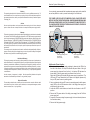
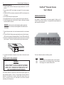
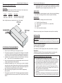
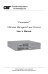
8 Omnitron Systems Technology, Inc. Omnitron Systems Technology, Inc. Hot Attachment of Power Supplies: 1. Unpack the power supply carefully. Inspect for any damages. If any damage is observed, do not use the power supply and call (949) 250-6510 to report the damage immediately and request a replacement unit. 2. Attach the power supply to the chassis and reconnect the 48VDC power source to the FlexPoint power supply. 3. Locate the 48VDC circuit breaker and switch the circuit breaker to the ON position. 4. Turn the FlexPoint Chassis power supply ON. 5. Observe the LED in the front of the chassis indicating that the power has been restored. FlexPointTM Powered Chassis 48VDC Power-Redundant 14-Module Chassis SPECIFICATIONS Indicators: Power ON: LED (2), Yellow, power applied Dimensions / Weight: W:19.0"xD:7.0"xH:3.5" / 9 lb. Power: 48VDC / 3.0 Amps (for model 4386) 2ea. 48VDC / 3.0 Amps (for model 4385) Environmental: Temperature: 0 to 50 degrees C Humidity: 5-95% (non-condensing) User’s Manual TECHNICAL SUPPORT If you encounter problems in installing this product, contact Omnitron Tech Support: Phone: (949) 250-6510 Fax: (949) 250-6514 Address: Omnitron Systems Technology, Inc. 140 Technology Drive, #500 Irvine, CA 92618, USA E-mail: [email protected] URL: http://www.omnitron-systems.com 040-04385-001B 11/07 140 Technology Drive #500 Irvine, CA 92618 (949) 250-6510; Fax: (949) 250-6514 2 Omnitron Systems Technology, Inc. 7 Safety Considerations Warning The operating description in this Instruction Manual is for use by qualified personnel only. To avoid electrical shock, do not perform any servicing of this unit other than that contained in the operating instructions, unless you are qualified and certified to do so by Omnitron Systems Technology, Inc. Caution All user-required operations can be performed without opening the unit. Never attempt to open or remove the cover or tamper with the unit or tamper with the power supply module. Warranty This product is warranted to the original purchaser against defects in material and workmanship for a period of TWO YEARS from the date of shipment. A LIFETIME warranty may be obtained by the original purchaser by REGISTERING this product with Omnitron within 90 days from the date of shipment. TO REGISTER, COMPLETE AND MAIL OR FAX THE REGISTRATION FORM INCLUDED WITH THIS INSTRUCTION MANUAL TO THE INDICATED ADDRESS. Or you may register your product on the Internet at http://www.omnitron-systems.com. During the warranty period, Omnitron will, at its option, repair or replace a product which is proven to be defective. For warranty service, the product must be sent to an Omnitron designated facility, at Buyer’s expense. Omnitron will pay the shipping charge to return the product to Buyer’s designated US address using Omnitron’s standard shipping method. Limitation of Warranty The foregoing warranty shall not apply to defects resulting from improper or inadequate use and/or maintenance of the equipment by Buyer, Buyer-supplied equipment, Buyer-supplied interfacing, unauthorized modifications or tampering with equipment (including removal of equipment cover by personnel not specifically authorized and certified by Omnitron), or misuse, or operating outside the environmental specification of the product (including but not limited to voltage, ambient temperature, radiation, unusual dust, etc.), or improper site preparation or maintenance. No other warranty is expressed or implied. Omnitron specifically disclaims the implied warranties of merchantability and fitness for any particular purpose. Exclusive Remedies The remedies provided herein are the Buyer’s sole and exclusive remedies. Omnitron shall not be liable for any direct, indirect, special, incidental, or consequential damages, whether based on contract, tort, or any legal theory. It is very strongly recommended that a replacement power supply unit be installed as soon as possible in order to prevent overheating of the chassis unit. THE POWER SUPPLIES ARE HOT-SWAPPABLE AND CAN BE REPLACED WITHOUT SHUTTING THE NETWORK DOWN. HOWEVER, WHEN REMOVING AND REPLACING A POWER SUPPLY UNIT, THE FOLLOWING STEPS MUST BE STRICTLY FOLLOWED IN ORDER TO PREVENT SERIOUS INJURY OR DEATH, OR SERIOUS DAMAGE TO YOUR EQUIPMENT. DC Power Input 48 V DC 48 VDC Present ON OFF 5 VDC DC Power Input 48 V DC 48 VDC Present DC Power Input ON 48 V DC OFF 5 VDC Power Supply Mounting Screws and guide pins. (2 each per unit) 48 VDC Present ON OFF 5 VDC Power Supply Mounting Screws and guide pins. (2 each per unit) Hot Removal of Power Supplies: 1. Determine which power supply needs replacing by observing the LEDs in the front left of the chassis: the top LED indicates the power status of the right power supply (as observed from the front), the bottom LED indicates the power status of the left power supply (as observed from the front). Notice that LED being ON indicates that the power supply is operational. The LED being OFF may indicate that the DC power is not applied, please verify that your DC power source is providing power. 2. Once you determine that your DC source is connected properly, and the power supply LED is still not ON, determine which is the failing power supply unit and proceed to the next step. 3. Locate the 48VDC circuit breaker, and switch the circuit breaker to the OFF position. 4. Remove the DC power cables of the faulty power supply from the FlexPoint power supply unit. 5. Loosen the 2 screws securing the power supply to the main chassis (observe the illustration above). 6. Remove the faulty power supply. 6 Omnitron Systems Technology, Inc. Omnitron Systems Technology, Inc.3 Cabling and Power-Up: 1. Insure that both FlexPoint Chassis power supply switches are in the OFF position. 2. Assure that the 48VDC circuit breaker can supply 3A of current per power supply. 3. Locate the 48VDC circuit breaker, and switch the 48VDC circuit breaker to the OFF position. 4. Cut the power cable to the length required. 5. Strip approximately 3/8 of an inch of insulation from the power cable wires. 6. Connect the power cables to the FlexPoint Chassis by fastening the stripped ends to the 48VDC connector. FlexPointTM Powered Chassis User’s Manual GENERAL DESCRIPTION The FlexPointTM Powered Chassis is a chassis capable of holding up to 14 FlexPointTM media converter modules. It is equipped with two power supplies in a power-redundant configuration. WARNING: Note the wire colors used for making the positive, negative and ground connections. Use the same color assignment for the connection at the circuit breaker. 7. Connect the power cable to the circuit breaker and switch the circuit breaker ON. 8. Turn both FlexPoint Chassis power supply switches on and check the power LED’s on the front panel of the powered chassis. The two LED’s should be ON. 9. Attach the L shaped tabs to the FlexPoint media converter units to be inserted into the chassis, Secure the FlexPoint module using the enclosed screws. 10. Save the unused tabs in a safe place or secure them to the chassis’ unused Slots. POWER SUPPLY REPLACEMENT WARNING! NEVER ATTEMPT TO OPEN OR SERVICE THE POWER SUPPLY UNIT. OPENING THE POWER SUPPLY UNIT MAY CAUSE SERIOUS INJURY OR DEATH. The Powered Chassis is intended to be used with two power supplies in a power-redundant operation. A failure of a single supply should not disturb the operation of the chassis unit. However, certain power supply failures may cause a secondary failure to the associated fan and cause undesired overheating of the chassis unit. This User’s Manual describes the following models: Model 4385 4386 4389 Description Powered Chassis, rack-mountable chassis, 2 power supplies Powered Chassis, rack-mountable chassis, 1 power supply Power supply unit for models 4385 and 4386 4 Omnitron Systems Technology, Inc. CONTROLS AND INDICATORS LEDs Display: The Powered Chassis features two LEDs on the left front of the chassis, these LEDs display the status of the two power supplies. Function Top LED Bottom LED Color/State Yellow / ON Yellow / ON Description Power OK in right power supply Power OK in left power supply Note: Left/right direction as viewed from the front of the chassis. Omnitron Systems Technology, Inc. 5 8. Wiring methods used for the connection of the equipment to the primary power supply shall be in accordance with the National Electrical Code, ANSI/NFPA 70, and the Canadian Electrical Code, Part I, C22.1. UNPACKING a. Visual Inspection: Inspect equipment in order to detect any physical damage. Any evidence of damage should be noted and reported immediately. INVENTORY Review contents, the following items should be included: (1) (2) (14) (14) (1) FlexPoint Powered Chassis unit. Power supplies (2 for model 4385, 1 for model 4386). L shape tabs. Screws User’s manual (this document). Please note any missing items or discrepancies and report them immediately. INSTALLATION WARNING: Only a DC power source that complies with safety extra low voltage (SLEV) requirements can be connected to the DC-input power supply. Tools and Equipment Required: SITE PREPARATION REQUIREMENTS 1. Power: Assure the 48VDC power can supply 3A of current. 2. The operating temperature of this equipment is 0-50 degrees C. If installed in a closed or multiunit rack assembly, the operating ambient temperature of the rack must not exceed the maximum rated 50 degrees C temperature. 3. Installation of the equipment should be such that the air flow in the front and back of the unit is not compromised or restricted. 4. Never use this equipment to carry any weight except its own, never use it as a shelf to support weight of other equipment. 5. Installing this equipment into a rack in such a way as to make it unstable may cause injury or death. Always make sure that the rack you are installing this equipment into is properly secure, stable, balanced and designed to carry the weight and weight distribution of this equipment. 6. When rack-mounting this equipment, the rack should be appropriately earth-grounded. 7. This equipment requires 48 VDC / 3.0 Amps per power supply. Appropriate overloading protection should be provided on all DC power source outlets utilized. Flat-head screwdriver (not supplied) Wire cutter/stripper (not supplied) Three-conductor 14 AWG copper power cable (recommended; not supplied) Preparation: Assure that the FlexPoint Chassis is physically installed in accordance with the Site Preparation Requirements outlined earlier in this document. WARNING REGARDING EARTHING GROUND: a) This equipment shall be connected to the DC supply system earthing electrode conductor or to a bonding jumper from an earthing terminal bar or bus to which the DC supply system earthing electrode is connected. b) This equipment shall be located in the same immediate area (such as, adjacent cabinets) as any other equipment that has a connection between the earthed conductor of the same DC supply circuit and the earthing conductor, and also the point of earthing of the DC system. The DC system shall not be earthed elswere. c) The DC supply source is to be located within the same premises as this equipment. d) There shall be no switching or disconnecting devices in the earthed circuit conductor between the DC source and the earthing electrode conductor.