1
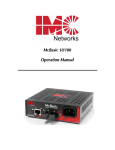
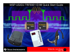
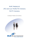
Installation
Guide
DIP Switch Location and Configuration Settings
iMcV-MediaLinX TX/FX
Dip Switch Settings for iMcV-MediaLinX TX/FX
S1
1
2
3
4
5
6
7
8
S2
1
2
3-8
About iMcV-M
MediaLinX TX/FX
iMcV-M
MediaLinX TX/FX™ is an SNMP-manageable, IEEE 802.3 10/100 switching
media converter from IMC Networks which converts both speed and media.
iMcV-MediaLinX TX/FX modules provide a single conversion between:
• 10Base-T twisted pair and 100Base-FX multi-mode fiber, or
• 10Base-T twisted pair and 100Base-FX single-mode fiber, or
• 100Base-TX twisted pair and 100Base-FX multi-mode fiber, or
• 100Base-TX twisted pair and 100Base-FX single-mode fiber.
iMcV-MediaLinX TX/FX modules feature one RJ-45 connector, one pair of ST or SC
fiber connectors and requires one slot in an SNMP-manageable iMediaCenter™ or
iMcV™ series chassis from IMC Networks.
iMcV-MediaLinX TX/FX is part of IMC Networks’ iMcV Series. Installation instructions for other iMcV Modules can be found in the “iMcV Module Installation Guide”
or in their respective installation guides. Install guides, as well as a variety of product literature and other information, can be found on the IMC Networks Web site
at http://www.imcnetworks.com/tech/techsup.asp.
Configuration Instructions
What Is TX LinkLoss?
Function
Default
Auto-Negotiation
ON
TX Port: HDX(ON) or FDX(OFF)
OFF
TX Port: 100(ON) or 10(OFF)
OFF
TX LinkLoss
OFF
FX LinkLoss
OFF
FX Port: HDX(ON) or FDX(OFF)
OFF
FiberAlert
OFF
Selective Advertising
OFF
Function
Default
Full-Duplex – Flow Control
OFF
Half-Duplex – Flow Control
OFF
Factory Default
Do Not Change
Auto-Negotiation & Selective Advertising Configuration Chart
Desired
Speed/Duplex
100 Mbps FDX
100 Mbps HDX
10 Mbps FDX
10 Mbps HDX
AutoNegotiation
ON
ON
ON
ON
Selective
Advertising
ON
ON
ON
ON
Speed
Duplex
100
100
10
10
FDX
HDX
FDX
HDX
NOTE: Selective Advertising is NOT an option when Auto-Negotiation is disabled.
Flow Control is used to throttle the END device to avoid dropping packets during network congestion. Full-Duplex Flow Control will Advertise ONLY in Full-Duplex Mode. Full-Duplex Flow Control
functions ONLY if link partner (end devices) also has Flow Control. Half-Duplex Flow Control DOES
NOT Advertise.
About LinkLoss and FiberAlert
iMcV-MediaLinX, TX/FX modules include the following troubleshooting features:
End-users may configure iMcV-MediaLinX TX/FX modules for various features. See
the DIP Switch Location and Configuration Settings chart on page 2 for information.
The following sections include instructions for configuring both managed (via an
SNMP-compatible management application like iView²) and unmanaged modules.
Managed Modules
To manage one or more iMcV Series modules, an SNMP agent must be also present in the chassis: iMediaCenter series chassis include embedded management;
iMcV series chassis require an iMcV-Master Module. When configuring managed
modules, install the module first (see page 4), then configure it using the management software. Within iView² for Media Converters, features and troubleshooting
functions are configured in the Module Detail section under the picture of the module. See the iView² online help file for more information.
N O T E
Management software will override any hardware settings (e.g., jumper, switch, etc.), so you MUST
configure a module that will be managed via the software. Until a module installed in a managed
chassis is configured via the software, the module (and its LEDs) may not work properly.
Unmanaged Modules
Before installing, iMcV-MediaLinx TX/FX modules may be configured for
LinkLoss, FiberAlert, Auto-Negotiation, duplex mode and speed. The illustrations
on page 2 include the available Dip Switch locations and configuration settings for
the iMcV-MediaLinx TX/FX modules.
I N S T A L L A T I O N
T I P
• FX LinkLoss (a.k.a. "Fiber LinkLoss" or just "LinkLoss")
• TX LinkLoss (a.k.a. “Twisted Pair LinkLoss” or “Reverse LinkLoss")
• FiberAlert
FiberAlert and LinkLoss are advanced troubleshooting features that can help locate
"silent failures" on your network. However, it is vital that you understand exactly how
FiberAlert and LinkLoss work, and how they will react in your network configuration,
before attempting to install the enclosed module(s).
Installing modules without understanding the effects of LinkLoss can cause perfectly
functioning units to appear flawed or even dead.
About Link Integrity
During normal operation, link integrity pulses are transmitted by all point-to-point
Ethernet devices. When an IMC Networks media converter receives valid link pulses, it
knows that the device to which it is connected is up and sending pulses, and that the copper or fiber cable coming from that device is intact. The appropriate “LNK” (link) LED is
lit to indicate this.
The IMC Networks media converter also sends out link pulses from its copper and
fiber transmitters, but normally has no way of knowing whether the cable to the other
device is intact and the link pulses are reaching the other end. Both TX and FX LinkLoss
allow this information to be obtained, even when physical access to a remote device (and
its link integrity LED) is not available.
TX LinkLoss is another troubleshooting feature. When a fault occurs on the twisted pair segment of a conversion, TX LinkLoss detects the fault and passes this information to the fiber segment. If a media converter is not receiving a twisted pair link,
TX LinkLoss disables the transmitter on the media converter's fiber port. This results in
a loss of link on the device connected to the fiber port.
What Is FiberAlert?
Local Site
FiberAlert minimizes the problems associated with
XMT
the loss of one strand of fiber. If a strand is unavailRCV
able, the IMC Networks device at the receiver end
RCV
LED
XMT
notes the loss of link. The device will then stop
transmitting data and the link signal until a signal or
LED
IMC Networks product with FiberAlert enabled —
link pulse is received. The result is that the link
Remote Site stops transmitting
Local Link LED is OFF indicating a break in the fiber loop
LED on BOTH sides of the fiber connection will go
out indicating a fault somewhere in the fiber loop. Using FiberAlert, a local site administrator is notified of a fault and can quickly determine where a cable fault is located.
Cable Break
Remote Site
LED OFF = Broken Link
N O T E
FiberAlert should only be enabled on one side of a media conversion. Enabling it on both
sides would keep both transmitters off indefinitely.
Using LinkLoss and FiberAlert
FiberAlert / LinkLoss Compared
In a typical main site to
Feature
Fault Location
Disabled LEDs
FiberAlert
Fiber
Fiber
remote site media conversion,
Fiber
Twisted Pair
IMC Networks recommends you FX LinkLoss
TX LinkLoss
Twisted Pair
Fiber
enable your media converters’
troubleshooting features as follows:
FX LinkLoss: Main Site
TX LinkLoss:
Remote Site Only
FiberAlert:
Remote Site Only
This will ensure that any faults, no matter where they occur, can be detected by an
administrator at the main site. For more information on LinkLoss and FiberAlert, please
visit the IMC Networks Web site at:http://www.imcnetworks.com/tech/ref-ffeatures.asp
If you are unsure of how best to implement these features in your configuration,
please contact IMC Networks technical support at (800) 624-1070 (U.S. and Canada),
+32-16-550880 (Europe) or via e-mail at: [email protected].
AutoCross Feature for Twisted Pair Connections
The twisted pair port of the iMcV-MediaLinX TX/FX module includes AutoCross, a
feature which automatically selects between a crossover workstation or pass-through/
repeater hub connection depending on the connected device.
Auto-N
Negotiation, Duplex Mode and Speed
The twisted pair port on iMcV-MediaLinX TX/FX auto-negotiates for speed and
duplex mode. These modules also provide the option of manually setting the speed
and duplex mode if the connected devices do not have the ability to auto-negotiate,
or when Auto-Negotiation is not preferred. The fiber port does not auto-negotiate; it
is always 100 Mbps with Half- or Full-Duplex operation selectable through the switch
settings or iView².
Auto-N
Negotiation
What Is FX LinkLoss?
When testing, IMC Networks recommends you test your module first in an unmanaged environment. To do this, turn the SNMP management switch to OFF on an iMediaCenter, or remove the
management module from an iMcV Series chassis. Follow the unmanaged configuration instructions
(above), then install the module, connect the cables and test the LEDs. When finished, reactivate
management and configure the unit via the software.
FX LinkLoss is a troubleshooting feature. When a fault occurs on the fiber segment of
a conversion, FX LinkLoss detects the fault and passes this information to the twisted pair
segment. If a media converter is not receiving a fiber link, FX LinkLoss disables the transmitter on the media converter's twisted pair port. This results in a loss of link on the
device connected to the twisted pair port.
iMcV-MediaLinX TX/FX ships from the factory with Auto-Negotiation enabled on the
twisted pair port. In this mode, the twisted pair port negotiates for speed and duplex
(i.e. the module autosenses 10 Mbps Full-Duplex, 10 Mbps Half-Duplex, 100 Mbps
Full-Duplex or 100 Mbps Half-Duplex with Flow Control). Configure AutoNegotiation on an iMcV-MediaLinX TX/FX by adjusting the DIP switch (for unmanaged
modules) or via the management software. Please see page 2.
1
2
3
Selective Advertising
Selective Advertising, when used in combination with Auto-Negotiation, advertises only the configured speed and duplex mode for the twisted pair port. If Selective
Advertising and Auto-Negotiation are both switched ON, the twisted pair port’s speed
(10 or 100 Mbps) and Duplex mode (FDX or HDX) can be separately configured per
your requirements. (See the Auto-Negotiation & Selective Advertising Configuration
Chart on page 2 for optional configurations using these features.)
If a specific speed and/or duplex mode is desired, it is recommended that you use
Selective Advertising rather than Force Mode, when connecting to devices that ONLY autonegotiate.
Forcing the Duplex Mode
The twisted pair and fiber ports on iMcV-MediaLinX TX/FX modules can each be
manually configured for either Half- or Full-Duplex operation. Before manually setting the duplex mode, Auto-Negotiation must be disabled (Set Dip Switch 1 on S1 to
OFF.)
• Configure the twisted pair port for Full-Duplex by setting Dip Switch 2
to the OFF position (Default).
• Configure the twisted pair port for Half-Duplex by setting Dip Switch 2
to the ON position.
• Configure the fiber port for Full-Duplex by setting Dip Switch 6 to the
OFF position (Default).
• Configure the fiber port for Half-Duplex by setting Dip Switch 6 to the
ON position.
•
•
Step 1: Connect the media converter to the twisted pair device with a
twisted pair cable.
Step 2: Loop a single strand of fiber from the transmit port to
the receive port of your media converter.
Step 3: Verify that you have both twisted pair and fiber link
(see LED operation on following page) on your media converter.
Make sure that you are using the appropriate twisted pair cable.
The fiber transmitters used on IMC Networks’ media conversion modules can
overdrive the receivers and cause data loss if used in installations where cable
power losses are low. To verify this, measure the optical power at the receiver.
The measured power should be no greater than specified and no less than the
Average Receive Sensitivity. For complete fiber specifications please visit our
Web site at: http://www.imcnetworks.com/adocs/fcs.asp
If measured power is greater than specified, install an optical attenuator to
bring power within specification. Contact IMC Networks for more information.
LED Operation
Twisted Pair LEDs
TX LL Glows green when TX LinkLoss is enabled.
100
Glows yellow when 100 Mbps is selected on port.
LNK/ACT
• Glows green when a link is established on port.
• Blinks green when data activity occurs.
FDX/COL
• Glows yellow when port is in Full-Duplex mode.
• Blinks yellow when port is operating in Half-Duplex mode
and collisions occur.
Forcing the Speed
The twisted pair port on iMcV-MediaLinX TX/FX can also be manually set for 10 or
100 Mbps operation (the fiber port always operates at 100 Mbps). Before manually
setting the speed, Auto-Negotiation must be disabled (Set Dip Switch 1 on S1 to the
OFF.)
Fiber Optic LEDs
FA
Glows green when FiberAlert is enabled.
FX LL Glows green when FX LinkLoss is enabled.
LNK/ACT
• Glows green when a link is established on port.
• Blinks green when data activity occurs.
FDX/COL
• Glows yellow when port is in Full-Duplex mode.
• Blinks yellow when port is operating in Half-Duplex mode
and collisions occur.
• Configure the twisted pair port for 10 Mbps operation by setting
Dip Switch 3 to the OFF position.
• Configure the twisted pair port for 100 Mbps operation by setting
Dip Switch 3 to the ON position.
Installing iMcV-M
MediaLinX, TX/FX Modules
iMcV-MediaLinX TX/FX modules may be installed in any IMC Networks iMcV series
or iMediaCenter series chassis. Each module requires one slot in the chassis.
To install a module, remove the blank brackets covering the slots where the module is to be installed (if present) by removing the screws on the outside edges of the
bracket. Slide the module into the chassis, via the card guides, until the module is
seated securely in the connector. Secure the module to the chassis by tightening the
captive screw. Save any “blanks” removed during installation for future use should
your configuration requirements change.
Installation Troubleshooting
•
•
•
During installation, first test your fiber and twisted pair connections with all
troubleshooting features disabled, then enable these features, if desired, just
before final installation. This will reduce the features’ interference with testing.
When working with units where the features cannot be disabled, you must
establish BOTH your twisted pair and fiber connections before the link LEDs
will light!
To test a media converter by itself, first make sure you have an appropriate
fiber patch cable, then follow these steps to test:
4
Fiber Optic Specifications
For fiber optic specifications, visit our Web site at:
http://www.imcnetworks.com/adocs/fcs.asp
Warranty Information:
Please contact IMC Networks for complete warranty information.
Fiber Optic Cleaning Guidelines
Fiber optic transmitters and receivers are extremely susceptible to contamination by particles
of dirt or dust which can obstruct the optic path and cause performance degradation. Good
system performance requires clean optics and connector ferrules.
1) Use fiber patch cords (or connectors, if you terminate your own fiber) only from a reputable supplier; low-quality components can cause many hard-to-diagnose problems in an
installation.
2) Dust caps are are installed at IMC Networks to ensure factory-clean optical devices.
These protective caps should not be removed until the moment of connecting the fiber
cable to the device. Assure that the fiber is properly terminated, polished and free of any
dust or dirt and that the location is as free from dust and dirt as possible.
3) Store spare caps in a dust-free environment such as a sealed plastic bag or box so that,
when reinstalled, they do not introduce any contamination to the optics.
4) Should it be necessary to disconnect the fiber device, reinstall protective dustcaps.
5) If you suspect that the optics have been contaminated, alternate between blasting with
clean, dry, compressed air and flushing with methanol to remove dirt particles.
Electrostatic Discharge Precautions
Electrostatic discharge (ESD) can cause damage to your add-in modules. Always observe the
following precautions when installing or handling an add-in module or any board assembly.
1) Do not remove unit from its protective packaging until you’re ready to install it.
2) Wear an ESD wrist grounding strap before handling any module or component.
If you do not have a wrist strap, maintain grounded contact with the system unit
throughout any procedure requiring ESD protection.
3) Hold boards by the edges only; do not touch the electronic components or gold
connectors.
WARNING! Integrated circuits and fiber optic components are extremely susceptible to electrostatic discharge damage. Do not handle these components directly unless you are a qualified
service technician and use tools and techniques that conform to accepted industry practices.
4) After removal, always place the boards on a grounded, static-free surface, ESD
pad or in a proper ESD bag. Do not slide the board over any surface.
General Information
IMC Networks Technical Support
Phone:
Fax:
E-M
Mail:
Web:
(949) 465-3000 or (800) 624-1070 (in the U.S. and Canada)
+32-16-550880 (Europe)
(949) 465-3020
[email protected]
www.imcnetworks.com
Visit www.mediaconverter.com for a complete overview of media
conversion products available from IMC Networks.
Questions or Comments about this manual? Contact [email protected]
19772 Pauling • Foothill Ranch, CA 92610-2611 USA
TEL: (949) 465-3000 • FAX: (949) 465-3020
www.imcnetworks.com
Specifications
Environmental
Operating Temperature: 32° - 104° F (0° - 40° C)
Storage Temperature: 0° - 160° F (-20° - 70° C)
Humidity: 5 - 95% (non-condensing)
Power Consumption (Typical)
Input Load: 500mA
5
© 2002-2003 IMC Networks. All rights reserved.
The information in this document is subject to change without notice. IMC Networks assumes no responsibility
MediaLinX, TX/FX is a trademark of IMC Networks. Other
for any errors that may appear in this document. iMcV-M
brands or product names may be trademarks and are the property of their respective companies.
Document Number 56-80911-00-A4
March 2003
6