1
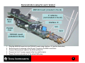
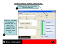
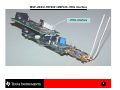
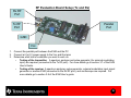
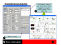
MSP-US/EU-TRF6901 EVM Quick Start Guide Written By: Juan Alvarez Oct - 02 1 Table of Content • Introduction (pg. 3) • Using the EVM as: – a link demonstration tool (pg. 4) – a code development tool (pg. 7) – an RF/device level evaluation tool (pg. 9) • Additional documentation (pg. 11) • Choosing an antenna (pg. 12) 2 Introduction • The EVM kit used for the TRF6901 transceiver has multiple uses depending on what you want to achieve. It can be used for link demonstration, code development, or stand-alone RF evaluation. – – – Link demonstration. 2 EVM kits can be used together to demonstrate a bi-directional halfduplex link using 2 PCs (so called “system mode’) Starts on page 4. Code development. The EVM kit can be used in conjunction with the MSP430 development tool and 1 PC to develop and implement code. Starts on page 7. RF evaluation. 1 EVM kit using 1 PC and RF test equipment can be used to evaluate the TRF6901 with the objective of looking at the RF reception and transmission. Starts on page 9. • The EVM kit is offered in 2 versions: – MSP-US-TRF6901. MSP430 pre-programmed with the European ISM band – MSP-EU-TRF6901. MSP430 pre-programmed with the US ISM band • The OBJECTIVE of this document is to get you started using the EVM kit. Other documentation provided more detailed information of how to use this tool. To download the EVM kit User’s guide, go to: – – Europe version: http://focus.ti.com/docs/apps/catalog/resources/appnoteabstract.jhtml?abstractName=swru006a US version: http://focus.ti.com/docs/apps/catalog/resources/appnoteabstract.jhtml?abstractName=swru005a 3 Link demonstration • • This section describes the steps required to set up a quick demonstration that will enable you to send text from one PC to another PC using a wireless link at 32 kbps. Hardware required: – – – – • Setup Hardware: – – – • Setup the 2 PCs wherever you want to demonstrate the RF link. Assemble each ‘station’ according to the figure on page 5 Review proper hardware and jumper setups in the EVM User’s Guide section 6.2.2. Setup Software: – – • 2 MSP-US-TRF6901 (or MSP-EU-TRF6901) EVM kits 4 antennas (See pg. 13 for how to choose an antenna) 2 PCs each equipped with 1 serial port 2 Power Supplies Download the file TRF6900 Demo_1_16.exe from the CD provided with the EVM kit located under the following directory: \MS-RF Chipset\Tools_Software\Setup_TRF6900 demo 1_16_Master Install the software on each PC. See a snap-shot on page 6 Establish a bi-directional link: – – See page 6 to start-up the software See section 7.7.5 of the EVM User’s guide for more information on how to run the software 4 Demonstration setup for each ‘station’ MSP430 board (included in the kit) 4” antenna (not included in the kit) Serial Port Parallel Port Interface ‘A’ Vcc Gnd TRF6901 board (included in the kit) 1. 2. 3. 4. 5. Plug the MSP430 board into the TRF6901 board using interface ‘A’ (per the illustration) Screw the pair of antennas to the Rx and Tx ports to the SMA connectors Connect the serial port cable to the EVM and the PC Connect a 6 to 8 V power supply to the Vcc and Gnd pins Repeat the same procedure for the other EVM setup 5 Link demonstration software start-up screen 1 Make sure that you choose the correct serial port Press the ‘Connect to serial port’ button to start the demo after connecting the EVM to the PC using the serial port 2 6 Code development • • This section describes the steps required to use the EVM as a code development tool and program the MSP430 uC. Hardware required: – – – – • Setup Hardware: – – • • 1 MSP-US-TRF6901 (or MSP-EU-TRF6901) EVM kit 1 PC equipped with 1 serial port 1 Power Supply 1 MSP-FET430P140 Assemble the ‘station’ according to the figure on page 5 Plug the ‘station’ into the MSP-FET430P140 using the JTEG interface connector provided on the EVM board (see page 8) Setup Software: – Download the MSP430 FET (Flash Emulation Tool) called ‘kickstart’ at http://focus.ti.com/docs/tool/toolfolder.jhtml?PartNumber=MSP430FREETOOLS – PLEASE KEEP IN MIND that to test your hardware you will need at least 2 stations to achieve a bi-directional link Develop code for the MSP430 – Develop code + FLASH the MSP430 according to the User manual included with the ‘kickstart’ tool set 7 MSP-US/EU-TRF6901 MSP430 JTEG interface JTEG interface 8 RF Evaluation • • This section describes the steps required to evaluate the TRF6901 device on a stand-alone . Hardware required: – – – – – – • Setup Hardware: – – – • 1 MSP-US-TRF6901 (or MSP-EU-TRF6901) EVM kit 1 PCs equipped with 1 parallel port 1 Spectrum Analyzer 1 Signal generator (or another EVM) 1 Oscilloscope 1 Power Supply Configure the EVM kit according to the figure on page 5 Assemble the test setup (more information on page 10) Review proper hardware and jumper setups in the EVM User’s Guide section 2.8.1. Setup Software: – – – Download the software from the internet at http://www-s.ti.com/sc/techzip/slwc026.zip Install the software on the PC. Check out 2 screen snap-shots on page 11 More information available on how to install and run the software on the EVM User’s Guide section 3 9 RF Evaluation Board Setup (Tx and Rx) Rx RF Port Tx RF Port Parallel Port GND Vcc 1. 2. 3. Connect the parallel port between the EVM and the PC Connect a 6 to 8 V power supply to the Vcc and Gnd pins Determine what kind of evaluation you want to work on: • Testing of the transmitter. A spectrum analyzer and pulse generator (for external modulation input) are required (connected to the Tx RF port). For more details go to section 3.7 of the EVM User’s Guide. • Testing of the receiver. A spectrum analyzer, pulse generator, external modulation input signal generator or another EVM (connected to the Rx RF port), and oscilloscope are required. For more details go to section 3.8 of the EVM User’s guide 10 RF Evaluation Software Snap shots 1 The software enables you to look at the block diagram (below) by double clicking on the 2 white box Start up screen 11 Additional Documentation More information available at www.ti.com/ismrf You will find multiple sources of information to help you solve your inquiries, including data sheets, application notes, reference designs, development software utilities, and FAQs 12 Choosing an Antenna • • Custom built: a custom-built antenna can be used while the designer focuses on developing the system. For this case, a 4” wire can be soldered to a SMA connector. Off-the-shelf: a designer may opt to purchase a pre fabricated tuned antenna. For this case, the designer needs to consider what frequency band is going to be used. In the next page are a few web sites that offer US or European ISM band antennas. Most antenna information can be found at the following URL http://www.rfcafe.com/vendors/components/antenna_links.htm • PCB antenna: Another alternative is to use a printed circuit board with a Cu trace as an antenna. There are multiple designs for this and readily available in different publications. 13 Antenna Manufacturers • http://www.superpass.com/902 -928M.html • http://www.maxrad.com/ • http://www.mobilemark.com/ • http://www.cushcraft.com • http://www.hyperlinktech.com/ web/antennas_900.php • http://www.antennaworld.com/ • http://www.aironet.com/ • http://www.lmelectronics.com/portable.htm • http://www.antenex.com/ • http://www.galtronics.com/wdat a.html • http://www.antstar.com/ • http://www.aatinternational.co m/default.htm • http://www.antennafactor.com/ adocs/main.html • http://www.dbiplus.com/produc ts.htm • http://www.radialllarsen.com/pr oducts/index.html • http://www.rangestar.com/ 14 IMPORTANT NOTICE Texas Instruments Incorporated and its subsidiaries (TI) reserve the right to make corrections, modifications, enhancements, improvements, and other changes to its products and services at any time and to discontinue any product or service without notice. Customers should obtain the latest relevant information before placing orders and should verify that such information is current and complete. All products are sold subject to TI’s terms and conditions of sale supplied at the time of order acknowledgment. TI warrants performance of its hardware products to the specifications applicable at the time of sale in accordance with TI’s standard warranty. Testing and other quality control techniques are used to the extent TI deems necessary to support this warranty. Except where mandated by government requirements, testing of all parameters of each product is not necessarily performed. TI assumes no liability for applications assistance or customer product design. Customers are responsible for their products and applications using TI components. To minimize the risks associated with customer products and applications, customers should provide adequate design and operating safeguards. TI does not warrant or represent that any license, either express or implied, is granted under any TI patent right, copyright, mask work right, or other TI intellectual property right relating to any combination, machine, or process in which TI products or services are used. Information published by TI regarding third–party products or services does not constitute a license from TI to use such products or services or a warranty or endorsement thereof. Use of such information may require a license from a third party under the patents or other intellectual property of the third party, or a license from TI under the patents or other intellectual property of TI. Reproduction of information in TI data books or data sheets is permissible only if reproduction is without alteration and is accompanied by all associated warranties, conditions, limitations, and notices. Reproduction of this information with alteration is an unfair and deceptive business practice. TI is not responsible or liable for such altered documentation. Resale of TI products or services with statements different from or beyond the parameters stated by TI for that product or service voids all express and any implied warranties for the associated TI product or service and is an unfair and deceptive business practice. TI is not responsible or liable for any such statements. Mailing Address: Texas Instruments Post Office Box 655303 Dallas, Texas 75265 Copyright 2002, Texas Instruments Incorporated