1
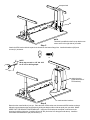
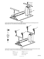
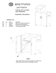
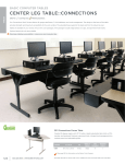
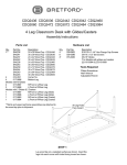
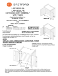
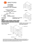
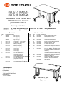
35XTC17 35XTC14
35XTC18 35XTC26
Adjustable Work Center with
CPU Holder and Casters
(30" DEPTH ONLY)
Assembly Instructions
35XTC17
35XTC14
36" wide one grommet hole
42" wide one grommet hole
35XTC18
Parts List
Qty.
1
2
1
1
1
1
2
2
Part No. Description
SA2339
Table Top (36")
SA2340
Table Top (42")
SA2341
Table Top (48")
SA2342
Table Top (72")
022-2036
Leg Assembly - Lower
022-1589
Leg Assembly - Upper Right
022-1590
Leg Assembly - Upper Left
010-2321
Modesty Panel (36")
010-3080
Modesty Panel (42")
010-2324
Modesty Panel (48")
010-2706
Modesty Panel (72")
010-2322
Cord Bin (36")
010-3081
Cord Bin (42")
010-2325
Cord Bin (48")
010-3075
Cord Bin (72")
010-3344
CPU Side Holder-w/hole
(1 required on 35XTC14,
35XTC17 & 35XTC18)
010-4981
CPU Holder w/Hole for MT Models
010-3343
CPU Side Holder-w/slot
(1 required on 35XTC14,
35XTC17 & 35XTC18)
010-4980
CPU Holder w/Slot for MT Models
48" wide
two grommet holes
Hardware List
Qty.
12
12
4
4
6
2
2
2
2
8
Ref.
AA
BB
CC
DD
EE
FF
HH
JJ1
JJ2
KK
8
LL
2
MM
2
NN
2
PP
1
Part No. Description
030-0402
#10-32 x 5/8" Combo Screw
030-0240
Washer, External Tooth
030-0396
3/8-16 x 1/2" Set Screw
030-0325
1/4-20 x 1/2" Combo Screw
030-0168
#8 x 1/2" Wood Screw
030-0433
#10-32 x 1/2" Knurled Knob Screw
030-0465
Retaining Washer - Nylon
015-0002
4" Caster without Lock
015-0003
4" Caster with Lock
030-0305
Washer, Flat (6 required on 35XTC14,
35XTC17 & 35XTC18)
030-0453
#12 x 3/4" Phillips Truss Head Screw
(4 reqiured on 35XTC14, 35XTC17 &
35XTC18)
030-0272
1/4-20 x 1/2" Carriage Bolt (1 reqiured
on 35XTC14, 35XTC17 & 35XTC18)
030-0306
Washer, Flat (1 reqiured on 35XTC14,
35XTC17 & 35XTC18)
030-0256
1/4-20 Flanged Nut (1 required on
35XTC14, 35XTC17 & 35XTC18)
030-0397
Allen Wrench
Tools Required
Phillips Screwdriver
Rubber Mallet
Allen Wrench (provided)
7/16" Open/Box End Wrench
Electric Drill
1/8" Dia. Drill Bit
35XTC26 72" wide,
two grommet holes,
two CPU holders
modesty panel
mounting holes
AA
BB
FRONT
Step 1
Lay the table top on a carpeted surface with holes facing up. Position the legs onto the table top with
the modesty panel mounting holes facing inward as shown. Loosely attach legs with screws (AA) and
washers (BB).
AA
BB
CC
REAR
Step 2
Set desired height of legs and insert set screws (CC) into legs and tighten with allen wrench provided.
CC
DD
EE
See Detail 'A'
Detail 'A'
Step 3
Slide the modesty panel between the two legs. Align the modesty panel mounting holes with the leg mounting
holes. Loosely install screws (DD). Secure the modesty panel to the table top with screws (EE) as shown in
Detail 'A'. Tighten all screws.
DD
EE
FF
HH
Detail 'B'
See Detail 'B'
Step 4
Insert screws (FF) into the cord bin flange with the embossed hole(s) . Then slide on the nylon washer (HH) to
capture the screw (as shown in Detail 'B'). Attach the cord bin to the modesty panel by hooking the rectangular slots onto the modesty panel hooks. Pivot the cord bin down to the table top to align the screw(s) on the
embossed flange and tighten.
FF
HH
square hole
LL
KK
NOTE:
The table is predrilled so the first cpu bracket can
mount on the left or right side of your table
Step 5
Attach the CPU bracket with the square hole located on the bottom flange first. Install with washers (KK) and
screws (LL) as shown.
KK
3"
4
LL
NOTE:
Wrap tape around an 1/8" dia. drill
bit at 3/4" for drilling depth.
tape
width of monitor
(inside dimension of
CPU brackets)
mark two hole locations
Step 6
Determine the overall width of your cpu. Place the other CPU bracket over the mounted CPU bracket as shown.
Adjust the space between the two brackets by sliding the bracket side to side to equal your cpu width. MAKE
SURE THAT THE BRACKETS ARE PARALLEL. Using the CPU bracket as a template, mark the two hole
locations for drilling pilot holes. Carefully drill an 1/8" dia. pilot holes 3/4" deep (see note above). Install the
second bracket with washers (KK) and screws (LL).
PP
NN
MM
Step 7
Install carriage bolt (MM) to the inside flange with washer (NN) and nut (PP) on the outside flange as shown.
Repeat steps 5, 6 & 7 for 35XTC-26 to install additional holder.
JJ1
JJ2
JJ1
JJ2
MM
NN
PP
Step 8
Install casters (JJ1) and (JJ2) into leg bottom as shown (a rubber mallet may be required to fully insert the caster
stem into leg). Carefully turn over the table and place into position and lock the casters.
Bretford
11000 Seymour Avenue
Franklin Park, IL 60131
TEL: 847.678.2545
800.521.9614
FAX: 847.678.0852
800.343.1779
Bretford Manufacturin Ltd.
2 Etongate
110 Windsor Road, Slough
Berkshire SL1 2JA England
TEL: 01753 539955
FAX: 01753 539478
www.bretford.com
Part #031-3543
Rev. 07.02.03 CZ