1
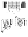
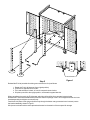
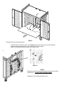
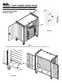
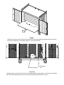
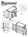
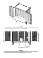
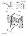
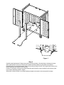
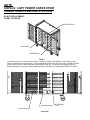
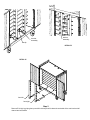
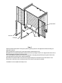
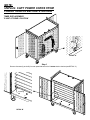
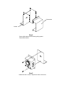
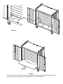
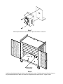
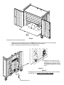
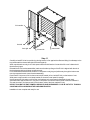
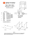
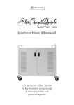
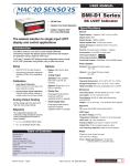
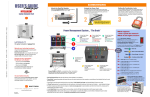
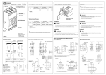
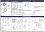
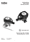
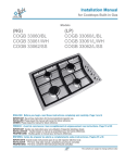
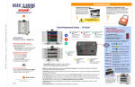
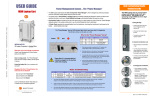
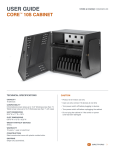
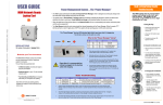
LAP30EBA LAP30EFR NOTEBOOK CART ASSEMBLY Assembly Instructions for: INTERIOR E-UNIT REPOSITIONING / REPLACEMENT AND TIMER INSTALLATION Qty. 1 LAP30EBA Parts List Part No. LAP30EBA LAP30EFR Description Cart Assembly, e-units at back Cart Assembly, e-units at front Tools Required MAXIMUM WEIGHT OF ACCESSORIES ON TOP OF CART: 25 LBS. Philips screwdriver NOTE: UNPLUG CART POWER CORDS FROM POWER SOURCE BEFORE STARTING LAP30EFR CAUTION: RISK OF ELECTRICAL SHOCK. DO NOT PLUG INTO ANOTHER RELOCATABLE POWER TAP. E-UNIT REPOSITIONING: 'FRONT TO REAR' SEE DETAIL 'B' bottom shelf SEE DETAIL 'A' Step 1 Open both front doors of cart to access E-Units. Unwind any length of E-Unit poer cord remaining on the exterior rear panel cord wrap brackets. From underneath the bottom shelf (see Front View), carefully unclip the power cords from the 4 clips located at the bottom panel of the cart. Loosen the screw holding the E-Unit bracket assembly and remove all 4 bracket assemblies (see DETAILS 'A' and 'B'). bracket assembly E-Unit power cord bottom shelf Front View bracket assembly clip DETAIL 'A' bracket assembly DETAIL 'B' front-left front-right Step 2 Remove front-left E-Unit by griping the top and tilt it side ways until it clears the underside of the cart interior shelf channel and set it aside. Remove front-right E-Unit by griping the top and tilt it side ways until it clears the underside of the cart interior shelf channel and set it aside. DETAIL 'C' Step 3 Remove 18 screws (2 per shelf) from rear panel that secure the 9 interior shelves (see DETAIL 'C'). mounting tab DETAIL 'D' Step 4 Remove each interior shelf by carefully pushing upward (to release shelf from mounting tabs) shown in Detail 'D', then carefully sliding out. Set each shelf aside. cutout window clip-rear round cutout Step 5 Figure 1 Reinstall the E-Units (set aside from being removed from the front) as follows: 1. Rotate the E-Unit 180 degrees (from original position). 2. Cross over to opposite corner of cart. 3. Tilt in and set bottom in back, in front of rear panel cutout window. 4. Grip the top and tilt to the upright position, underneath top panel bracket. When repositioned correctly, the E-Unit power switch should be visible from rear panel cutout window. Reinstall the E-Unit bracket assemblies (make sure that the top flange of the E-unit is aligned with the slot in the bracket assembly) and tighten screws securely. Feed the E-Unit power cords (plug end) all the way through the bottom rear grommeted round coutouts (next to the bracket assembly) shown in Figure 1. Wind power cords around the cord wrap brackets located on the exterior of the rear panel for storage. tab notch Step 6 Reinstall the 9 interior shelves as follows: 1. Carefully slide in the shelf with notch, at the bottom position (the notch will rest on the bracket tab). (Make sure that the shelf flanges are ALL seated into the mounting tabs.) 2. Slide in all remaining shelves into position as the bottom shelf. DETAIL 'E' Step 7 Reinstall 18 screws to rear panel that will secure the 9 interior shelves (see DETAIL 'E). DO NOT OVER TIGHTEN SCREWS. Installation is now complete and ready for use. NOTE: UNPLUG CART POWER CORDS FROM POWER SOURCE BEFORE STARTING E-UNIT REPOSITIONING: 'REAR TO FRONT' DETAIL 'A' Step 1 Remove 18 screws (2 per shelf) from rear panel that secure the 9 interior shelves (see DETAIL 'A'). mounting tab DETAIL 'B' Step 2 With both doors open, remove each interior shelf by carefully pushing upward (to release shelf from mounting tabs) shown in Detail 'B', then carefully sliding out. Set each shelf aside. bracket assembly E-Unit power cord Front View Unwind the power cord of the E-Units from the cord wrap brackets (on the rer panel). Loosen the screw holding the E-Unit bracket assembly and remove all 4 bracket assemblies (see DETAILS 'C' and 'D'). DETAIL 'C' DETAIL 'D' clip-rear Step 3 Remove rear-right E-Unit by griping the top and tilt it side ways until it clears the underside of the cart interior shelf bracket and set it aside. notch tab Step 4 Reinstall the 9 interior shelves as follows: 1. Carefully slide in the shelf with notch at the bottom position (the notch will rest on the bracket tab). (Make sure that the shelf flanges are ALL seated into the mounting tabs.) 2. Slide in all remaining shelves into position as the bottom shelf. DETAIL 'F' Step 5 Reinstall 18 screws to rear panel that will secure the 9 interior shelves (see DETAIL 'F'). DO NOT OVER TIGHTEN SCREWS. offset clip Step 6 Reinstall the E-Units (set aside from being removed from the rear) as follows: 1. Rotate the E-Unit 180 degrees (from original position). 2. Position to the front of cart. 3. Tilt in and set against offset of bottom panel (of cart). 4. Grip the top and tilt to the upright position. When repositioned correctly, the E-Unit power switch should face the front. Reinstall the E-Unit bracket assemblies (make sure that the top flange of the E-unit is aligned with the slot in the bracket assembly) and tighten screws securely. From underneath the bottom shelf, feed the E-Unit power cords (plug end) all the way through the bottom rear round grommeted cutouts (next to bracket assembly). Press each E-Unit power cord into the two wire clips located (in line, behind E-Unit) on the bottom of cart. Wind power cords around the cord wrap bracket on the rear panel for storage. Installation is now complete and ready for use. NOTE: UNPLUG CART POWER CORDS FROM POWER SOURCE BEFORE STARTING E-UNIT REPLACEMENT: 'REAR LOCATION' DETAIL 'A' Step 1 Remove 18 screws (2 per shelf) from rear panel that secure the 9 interior shelves (see DETAIL 'A'). mounting tab DETAIL 'B' Step 2 With both doors open, remove each interior shelf by carefully pushing upward (to release shelf from mounting tabs) shown in Detail 'B', then carefully sliding out. Set each shelf aside. bracket assembly E-Unit power cord Front View Unwind the power cord of the E-Units from the cord wrap brackets (on the rer panel). Loosen the screw holding the E-Unit bracket assembly and remove all 4 bracket assemblies (see DETAILS 'C' and 'D'). DETAIL 'C' DETAIL 'D' clip-rear Step 3 Remove E-Unit(s) by griping the top and tilt it side ways until it clears the underside of the cart interior shelf bracket and set it aside. cutout window clip-rear round cutout Figure 1 Step 4 Carefully install replacement E-Unit(s) into position by placing bottom in first and tilting in sideways to the top. When repositioned correctly, the E-Unit(s) power switch should be visible from rear panel cutout window. Reinstall the E-Unit bracket assemblies (make sure that the top flange of the E-unit is aligned with the slot in the bracket assembly) and tighten screws securely. Feed the E-Unit power cord(s) [plug end] all the way through the bottom rear grommeted round coutout(s) [next to the bracket assembly] shown in Figure 1. Wind power cord(s) around the cord wrap bracket(s) located on the exterior of the rear panel for storage. tab notch Step 5 Reinstall the 9 interior shelves as follows: 1. Carefully slide in the shelf with notch, at the bottom position (the notch will rest on the bracket tab). (Make sure that the shelf flanges are ALL seated into the mounting tabs.) 2. Slide in all remaining shelves into position as the bottom shelf. DETAIL 'E' Step 6 Reinstall 18 screws to rear panel that will secure the 9 interior shelves (see DETAIL 'E). DO NOT OVER TIGHTEN SCREWS. Installation is now complete and ready for use. NOTE: UNPLUG CART POWER CORDS FROM POWER SOURCE BEFORE STARTING E-UNIT REPLACEMENT: 'FRONT LOCATION' SEE DETAIL 'B' bottom shelf SEE DETAIL 'A' Step 1 Open both front doors of cart to access E-Unit(s). Unwind any length of E-Unit power cord remaining on the exterior rear panel cord wrap bracket(s). From underneath the bottom shelf (see Front View), carefully unclip the power cord(s) from the 2 clips located at the bottom panel of the cart. Loosen the screw holding the E-Unit bracket assembly and remove (2) bracket assemblies of the E-Unit(s) to be replaced (see DETAILS 'A' and 'B'). bracket assembly bottom shelf Front View E-Unit power cord clip bracket assembly bracket assembly DETAIL 'B' DETAIL 'A' front-left front-right Step 2 Remove E-Unit(s) by griping the top and tilt it side ways until it clears the underside of the cart interior shelf channel and set it aside. bottom shelf offset front-left clip front-right Step 3 Carefully install replacement E-Unit(s) into position by placing bottom in first against the offset and tilting it in sideways to the top. When repositioned correctly, the E-Unit(s) power switch should face the front. Reinstall the E-Unit bracket assemblies (make sure that the top flange of the E-unit is aligned with the slot in the bracket assembly) and tighten screws securely. From underneath the bottom shelf, feed the E-Unit power cord(s) [plug end] all the way through the bottom rear round grommeted cutout(s) [next to bracket assembly]. Press each E-Unit power cord into the two wire clip(s) located [in line, behind E-Unit] on the bottom of cart. Wind power cord(s) around the cord wrap bracket on the exterior rear panel for storage. Installation is now complete and ready for use. NOTE: UNPLUG CART POWER CORDS FROM POWER SOURCE BEFORE STARTING TIMER REPLACEMENT: 'E-UNIT AT REAR LOCATION' DETAIL 'A' Step 1 Remove 6 screws (2 per shelf) from rear panel that secure the 3 bottom interior shelves (see DETAIL 'A'). mounting tab DETAIL 'B' Step 2 With both doors open, remove the 3 bottom interior shelves by carefully pushing upward (to release shelf from mounting tabs) shown in Detail 'B', then carefully sliding out. Set each shelf aside. E-Unit bracket assembly bottom flangebracket assembly Step 3 Remove 2 screws from bottom flange (securing bracket to bottom of cart) and remove bracket assembly. The EUnit bracket assembly shown above, will need to be removed (with a philips screwdriver) to allow the E-Unit to swing back. This will allow the timer cord plug to pass between the E-Unit and rear panel. filler bracket bracket Step 4 Remove filler bracket from bracket by pulling upward. Discard filler bracket. Step 5 Install timer with 2 screws. Adjust timer dial to current time. E-Unit cord timer cord bottom flangetimer/bracket Step 6 Install timer/bracket assembly onto bottom, rear of cart with 2 screws (into bottom flange of timet bracket). Make sure timer face is aligned with rear panel cutouts. Tighten screws. Feed the power cord from the timer out the grommeted hole shown. Unwind enough E-Unit power cord from the cord brackets on the rear panel to feed back through each grommeted hole and into the timer. Plug one E-Unit power cord into the bottom outlet of the timer marked 'A' only and the other E-Unit power cord into the bottom outlet of the timer marked 'B' only. DO NOT PLUG BOTH E-UNIT POWER CORDS INTO ONE SIDE MARKED 'A' OR 'B' OUTLETS. THIS WILL CAUSE AN OVER LOAD DURING THE CHARGING PROCESS. notch tab Step 7 Reinstall the 3 interior shelves as follows: 1. Carefully slide in the shelf with notch at the bottom position (the notch will rest on the bracket tab). (Make sure that the shelf flanges are ALL seated into the mounting tabs.) 2. Slide in remaining 2 shelves into position as the bottom shelf. timer power cord Adjust timer to current time when installation is complete and ready to be plugged back into power source. If necessary, adjust tabs for charging times. DETAIL 'C' Step 8 Reinstall 6 screws to rear panel that will secure the 3 interior shelves (see DETAIL 'C'). DO NOT OVER TIGHTEN SCREWS. Installation is now complete and ready for use. NOTE: UNPLUG CART POWER CORDS FROM POWER SOURCE BEFORE STARTING TIMER INSTALLATION: 'E-UNIT AT FRONT LOCATION' SEE DETAIL 'B' Please read and follow all instructions thoroughly. Bretford will not be held responsible for improper installation or misuse of the timer unit. bottom shelf SEE DETAIL 'A' Step 1 Open both front doors of cart to access E-Units. Unwind any length of E-Unit power cord remaining on the back panel cord wrap brackets. Unclip the power cords from the side panel clips (see DETAIL 'A'). Loosen the screw holding the E-Unit bracket assembly and remove all 4 bracket assemblies (see DETAILS 'A' and 'B'). clip bracket assembly bracket assembly DETAIL 'B' DETAIL 'A' front-left front-right Step 2 Remove front-left E-Unit by griping the top and tilt it side ways until it clears the underside of the cart interior shelf channel and set it aside. Remove front-right E-Unit by griping the top and tilt it side ways until it clears the underside of the cart interior shelf channel and set it aside. DETAIL 'A' Step 3 Remove 6 screws (2 per shelf) from rear panel that secure the 3 bottom interior shelves (see DETAIL 'A'). mounting tab DETAIL 'B' Step 4 With both doors open, remove the 3 bottom interior shelves by carefully pushing upward (to release shelf from mounting tabs) shown in Detail 'B', then carefully sliding out. Set each shelf aside. bottom flangebracket assembly Step 5 Remove 2 screws from bottom flange (securing bracket to bottom of cart) and remove bracket assembly. filler bracket bracket Step 6 Remove filler bracket from bracket by pulling upward. Discard filler bracket. Step 7 Install replacement timer with 2 screws. Adjust timer dial to current time. hole location bottom flangetimer/bracket Step 8 Install timer/bracket assembly onto bottom, rear of cart with 2 screws. Feed the power cord from the timer out the grommeted hole shown. Make sure timer face is aligned with rear panel cutouts. Tighten screws. notch tab Step 9 Reinstall the 3 interior shelves as follows: 1. Carefully slide in the shelf with notch at the bottom position (the notch will rest on the bracket tab). (Make sure that the shelf flanges are ALL seated into the mounting tabs.) 2. Slide in remaining 2 shelves into position as the bottom shelf. Adjust timer to current time when installation is complete and ready to be plugged back into power source. If necessary, adjust tabs for charging times. DETAIL 'C' Step 10 Reinstall 6 screws to rear panel that will secure the 3 interior shelves (see DETAIL 'C'). DO NOT OVER TIGHTEN SCREWS. timer power cord full row side offset front-left front-right full row side Step 11 bottom shelf Carefully reinstall E-Units into position by placing bottom in first against the offset and tilting it in sideways to the top (underneath the channel bracket of the cart top panel). When repositioned correctly, the E-Units power switch should face the front and the full row of outlets should face the door hinges. Reinstall the E-Unit bracket assemblies (make sure that the top flange of the E-Unit is aligned with the slot in the bracket assembly) and tighten screws securely. From underneath the bottom shelf, feed the E-Unit power cords (plug end) all the way through the bottom rear round grommeted cutouts (next to bracket assembly). Press each E-Unit power cord into the two wire clips located (in line, behind E-Unit) on the bottom of cart. Wind power cords around the cord wrap bracket on the exterior rear panel for storage. Unwind enough E-Unit power cord from the cord brackets on the rear panel to feed back through each grommeted hole and into the timer. Plug one E-Unit power cord into the bottom outlet of the timer marked 'A' only and the other E-Unit power cord into the bottom outlet of the timer marked 'B' only. DO NOT PLUG BOTH E-UNIT POWER CORDS INTO ONE SIDE MARKED 'A' OR 'B' OUTLETS. THIS WILL CAUSE AN OVER LOAD DURING THE CHARGING PROCESS. Installation is now complete and ready for use. LABEL INSTALLATION: $8; $8; $8; $8; $8; $8; peel off and attach corresponding labels to shelves and E-Units. suggested installation of labels shelf E-Unit E-Unit E-Unit at front suggested label direction E-Unit at rear PAD LOCK - DOOR: Open Lock The First Time 1) Set the combination to 0-0-0-0 2) Depress shackle and pull open. To Set You Own Combination **REMEMBER: Combination can only be set when lock is open. 1) Insert reset tool (included in package) in hole on side of lock. 2) Push key in and turn key 90 degrees in either direction. (Key automatically stays in this position). Failure to exert force while pushing key in will result in a failed attempt to set or reset combination. 3) Set wheels to desired combination. 4) Turn and remove reset tool. Lock is now set to new combination. **BE SURE TO RECORD YOUR COMBINATION. 5) To lock scramble the wheels and close the shackle. 6) To reopen dial your combination and depress shackle. Bretford Bretford Ltd. 11000 Seymour Avenue 2 Etongate Franklin Park, IL 60131 110 Winsor Road, Slough TEL: 847.678.2545 Berkshire SL1 2JA England 800.521.9614 TEL: 01753 539955 FAX: 847.678.0852 FAX: 01753 539478 800.343.1779 www.bretford.com Part #031-6609 Rev. 08.29.05 CH