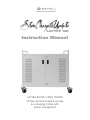
1
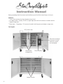
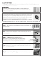
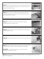
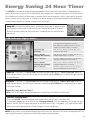
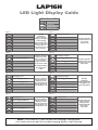
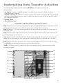
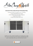
LAPTOP 16H
Instruction Manual
LAP16H B/EPM; F/EPM, FN/EPM
16 Bay Horizontal laptop storage
& recharging trolley with
power management
Instruction Manual
Before proceeding check the contents and familiarise yourself with the internal layout of the cart.
··
·
Contents:2 sets x front and rear door keys (located on top of cart).
IEC adaptor leads - Quantity 16 x IEC to figure eight and clover leaf connectors located inside the
laptop storage area.
Mains lead = 13amp plug – IEC connector located inside the power and adaptor storage area.
Cart layout:IEC power strip
Area for mounting
a network switch
(network switch
not included)
Power pack
storage area
Timer module
Laptop shelves
1
LAPTOP 16H
The LAP16H is specifically designed for the storage and recharging of up to laptops. To assemble/configure your new
charging trolley, simply follow the steps below...
Ventilation:
All vents MUST be kept clear at all times, no posters etc. covering the perforations.
Also ensure there is a minimum of 50mm clearance between the back and sides of the
cabinet to ensure good air flow.
Fans
If fans are fitted: Whilst charging, if the temperature in the cabinet exceeds 30° the fans will
automatically initiate. The fan guards MUST be kept clear at all times, including allowing a
minimum of 75mm clearance between the back of the cabinet and the wall to ensure good
air flow. The fans will continue to run until the temperature drops below 30°.
However, if the room has a high ambient temperature this may cause the fans to remain on.
DO NOT CONNECT TO THE MAINS SUPPLY UNTIL STEPS 1-10 ARE COMPLETE
Step 1: Open the rear doors to reveal 16 power pack shelves and the IEC power strip.
As shown on page 1.
Step 2: Remove the mains/3pin plug lead (if fitted) from the laptop power pack and
store in a safe place.
Step 3: All LAP16H models are supplied with 16 x IEC to
figure of eight & 16 x IEC to cloverleaf cables to be connected into the
laptop power pack & the IEC power strips. Firstly select the leads with
corresponding connector for the power packs being used in the cart.
IEC
Clover leaf
Figure of eight
Step 4: Connect an IEC connector into the top IEC power strip. Continue this action
until all 16 IEC leads are connected.
Step 5: Starting with the top IEC lead plug the connector in to the laptops power pack.
2
Step 6: Then place the power pack onto the rear storage area of the top shelf and
push the laptops connecting lead through to the front of the shelf. Repeat until all
power packs and leads are in place.
Step 7: Move to the front of the cabinet, unlock and open the front doors to
reveal 8 horizontal laptop shelves. Select one of the connecting leads, previously
fed through & plug it into the laptop.
Step 8: Place the laptop onto the shelf and repeat until all laptops are
connecting and in place - 2 laptops per shelf.
Step 9: Feed the IEC connector end of the supplied 2m mains lead through the
hole in the side of the trolley.
Step 10: Plug the mains lead into the IEC socket on the side of the timer module.
Step 11: Plug the trolley’s mains lead in to a switched wall socket and switch ON.
Switch on the unit’s own ON/OFF switch located above the mains lead input.
IMPORTANT - Ensure the wall socket switch is in the OFF position before
connecting and removing the mains plug
NOTE: When the unit is first turned ON, it will automatically divert to constant charging mode. To set the 24 hour
timer, refer to the steps below.
3
Energy Saving 24 Hour Timer
The LAP16H is fitted with an energy saving programmable 24 hour timer. Each timer features 2 programable timer
options allowing you to set your unit to automatically start charging over 2 separate time periods in one 24 hourcycle.
This could be from 6:30am to 8:30am ready for morning classes and then again at 12pm to 1pm ready for afternoon
classes. The timer can also be set be set to charge your laptops during the evening or weekend to take advantage of
off-peak energy supply hours, helping to reduce your electricity bills.
Step 12: First check the 24 hour clock is showing the correct time. To adjust the time,
press & hold the control knob in until the clock starts flashing (Minimum 10 seconds).
Then turn the control knob until the correct time is reached & press the control knob in
again to set.
LED Indicator Lights Guide:
Charging
When this LED is ON, it indicates that the unit is
receiving power and charging is in progress.
When flashing the charging start time is set and
charging will commence within 2-3 minutes.
Timed Charging
(Flashing)
When this LED is flashing it indicates that a timer
selection has been made.
Timer 1: ON Time
(Flashing: This timer ON)
When this LED is flashing it indicates that the unit is
charging and that Timer 1 is selected.
Timer 1: OFF Time
This LED is normally OFF and only comes ON when
setting the Charging Finish time of Timer 1.
Timer 2: ON Time
(Flashing: This timer ON)
When this LED is flashing it indicates that the unit is
charging and that Timer 2 is selected.
Timer 2: OFF Time
This LED is normally OFF and only comes ON when
setting the Charging Finish time of Timer 2.
Step 13: To set Timer 1’s charging START time turn the knob to light the LED “Timer 1: ON Time”& push to
select (indicator flashes). Turn the control knob until the desired charging START time is reached, then press again to
set (stops flashing).
Step 14: To set Timer 1’s charging finish time turn the knob to light the LED “Timer 1: OFF Time”& push to
select (indicator flashes). Turn the control knob until the desired charging FINISH time is reached, then press again
to set (stops flashing).
Repeat the steps above for Timer 2
Note: If you do not require a second charging session simply leave the ON/OFF times the same.
Constant Charging Mode:
To use the LAP16H in constant charging mode set both timers ON/OFF times to the same time.
To commence charging turn the knob to the top “Charging Indicator” LED and simply press for ON and then press
again to turn OFF. The LED display will present as fig 8 then settle to fig 2. ( See page 5 – LED Light Display Guide)
When in constant charging mode the ‘Timed Charging’ LED will stop flashing.
NOTE: Once you have set the desired charging start & finish times, this action does not need to be repeated unless you
want to adjust these times. These pre-set times will be saved in the Timer Module.
4
LAP16H
LED Light Display Guide
LED Indicator KEY:
LED light OFF
LED light ON
LED light flashing
Figure 1
Figure 2
Charging in progress
This light
combination
indicates that NO
charging is taking place.
This light combination
indicates that the unit
is in constant
charging mode.
To start charging
first check the unit is
switched on then either
press the knob for
constant charging or set
Timer 1 or Timer 2.
Figure 3
Figure 4
Timed Charging Mode On
Charging in progress
This light combination
indicates that either
Timer 1 or Timer 2 has
been set, but the
charging start time has
not yet been reached.
Timed Charging Mode On
This light combination
Timer 1 Charging Period Started indicates that the unit is
charging for the period
set by Timer 1
No charging is taking
place at this point
in time
Figure 6
Figure 5
Charging in progress
Charging passed
Timed Charging Mode On
Timer 1 Charging Period
This light combination
indicates that Timer 1
charging period has
been selected but the
unit is waiting for the
Timer Module to reset
Timed Charging Mode On
This light
combination
indicates that the unit
is charging for the
period set by Timer 2
Timer 2 Charging Period Started
Figure 7
Figure 8
Charging passed
Timed Charging Mode On
Timer 2 Charging Period
Charging Passed
This light combination
indicates that Timer 2
charging period has
been selected but the
unit is waiting for the
Timer Module to reset
This light combination
indicates that the
charging circuit is
resetting which will
take 2/3 mins.
Please wait.
NOTE: If the time LED is not ON then NO charging is taking place.
Unit needs to be turned ON to enable charging options to be selected.
5
Undertaking Data Transfer Activities
To undertake data transfer activities with the LAP16H you will need to purchase the
following items…
• Fan Upgrade - Available as an optional upgrade. If ordered at the same time as the LAP16H cart then they
will be pre-fitted prior to delivery
• Network Lead Loom Kit - Available as an optional upgrade. The kit includes 2 x 8 network lead looms, all bound &
pre-cut to the required lengths for easy to install. If ordered at the same time as the LAP16H cart then this kit will be
pre-installed prior to delivery.
• Network Switch
• IEC to IEC power lead
DISCONNECT THE UNIT FROM THE ELECTRICAL SUPPLY!
Step 1: Open the rear doors of the unit to access the 19” rack mounting brackets located on the right hand side of the
cabinet. Then attach the network switch to the mounting brackets. (Network switch not provided)
Step 2: Plug the IEC to IEC mains lead (Not provided) into the Timer Module on the cart and into the mains input on
the network switch.
Step 3: Connect a network cable into the network switch and then feed the other end out through the grommet hole
on the side of the cart into a LAN socket.
Step 4: Take the network lead looms and connect the equal length ends into the network switch. Connect the loom
labelled 1-8 into the left hand side of the switch and the loom labelled 9-16 into the right hand side of the switch*.
Step 5: Feed the other end of the network leads into the corresponding laptop shelves and connect into the laptops
Your LAP16H is now networked and ready for use with Data Transfer Activities.
*NOTE: If the Network Loom Kit is ordered at the time of initial purchase, then the 2 network lead looms will be
pre-fitted in the cabinet.
1
16
2
15
3
14
4
13
5
12
6
11
7
10
8
9
Network loom 9-16
Network loom 1-8
6
Frequently Asked Questions
Q. I have followed the configuration guidelines yet my laptops do not appear to be charging?
A. Is the unit in Timed Charging mode?
Open the rear door of the cart to view the power module. View the LED display. (Refer to LED light Display guide
on page 10. If fig.3 is displayed then a timed, charging period has been selected but the start time has not yet been
reached. To start charging either reset Timer 1 or 2 to the required times or set both timers ON/OFF times to the
same time to initiate constant charging. The LED display will present as fig.8 then settle to fig.2.
Q. The unit is not in Timed Charging Mode yet my laptops still do not appear to be charging?
A. Complete the checks below...
i.
ii.
iii.
iv.
v.
vi.
Check the unit is plugged into a mains supply wall socket and that the socket is switched on
Check that the mains socket is not faulty. Try connecting a known working piece of equipment e.g. radio
Check there is a fuse in the mains plug
Check the mains lead is correctly inserted into the cabinet.
Check that the On-Off switch on the cabinet is switched on, 1 pressed down = on
Check that all other leads are correctly inserted into the cabinet and/or the laptops
If the unit still isn’t charging refer to the LED light display guide on page 10, before making a note of the
LED display light combination lit on the power module and contacting your supplier or Bretford directly
Q. Some but not all of my laptops are charging?
A. A fuse may need replacing
i. There are 4 IEC power strips in the rear of the unit, one on each side and two at the base. Each IEC power strip
features a fuse compartment. There is also a fuse in the power module, located alongside the ON/OFF switch.
Check if a fuse has blown, remove the fuse and replace with a 10a fuse if necessary.
ii. If no fuses need replacing, check that the laptops are charging correctly when plugged directly into a known
working mains wall socket.
If NO then see your laptop’s own handbook or contact your laptop supplier.
If YES make a note of the LED display light combination lit on the power module, then contact your supplier or
Bretford directly
Q. The mains lead is damaged!
A. DO NOT CONTINUE TO USE! Disconnect the mains lead from the wall socket and discard in compliance with the
WEEE directive. Contact your supplier or Bretford for a replacement part.
Q. Can I use the unit to charge other items?
A. This unit is designed for the storage and recharging of laptops only and you should not use this unit for recharging
any other devices.
7
Safety and Security Guidance
• This unit is designed for storage and re-charging of laptops only
• To avoid damage, please ensure that the laptops are inserted & removed by an adult or competent person
• All vents MUST be kept clear at all times, including allowing enough space between the back of the cabinet and the wall to
ensure good air flow (50mm Minimum)
• This unit should be used with a switched wall socket ONLY
• IMPORTANT - Ensure the wall socket switch is in the ‘off’ position before connecting and removing the mains plug
• The cart is lockable to prevent opportunist theft only. For maximum security, the unit should be returned to a secure, alarmed
area
• As with all mobile products the unit should be manoeuvred with care, especially on inclines, by an adult or competent person
• To move the unit, first ensure the mains lead is disconnected from the mains and wrapped around the handle, PUSH using the
handles, DO NOT PULL This unit is not designed to be wheeled outside or over uneven surfaces
• The mains lead should be checked regularly to ensure there is no damage to the plug, lead or connector. In the event of damage
do not continue to use! Discard the mains lead in compliance with the WEEE directive and contact your supplier or Bretford for a
replacement part
• Unless otherwise directed by Bretford Manufacturing Ltd, DO NOT remove the power module/timer unit. This action will
invalidate the warranty
• Total current must NOT exceed 10A, only use 10A fuse in mains plug
• No single item of ICT equipment used with the unit should have a rated current consumption exceeding 5A
• All individual ICT chargers used in this cabinet should be fused/protected at 5A
Mains Lead Safety: When fitting the mains lead ensure that the IEC plug is correctly connected. Do not trap or run the mains
lead or plug under the cart wheels - surplus lead should be wound around the handles of the unit before moving. In the event of
damage do not continue to use. Discard the mains lead in compliance with the WEEE directive and contact your supplier or
Bretford for a replacement part.
24 Hour Programmable Energy Saving Timer
The RM moveIT is fitted with a 24 hour timer with 2 programmable options. If the cart appears to have stopped charging it may be
that the unit has completed one of its pre-set timed charging cycles. To re-start charging, simply switch to the constant charging
mode or re-set the timers. Unless a timer is set the cart will charge continuously until it is turned off manually.
Compliance
The unit is tested & CE certified ensuring the highest levels of electrical/build safety and complies with the HSE October 2009
Manufacturing Guidelines on electrical safety.
WEEE Directive
When the unit becomes redundant, it must be disposed of in compliance with the WEEE Directive 2005. Contact your Local
Authority or supplier in the first instance
Bretford Manufacturing Ltd
2 Etongate, 110 Windsor Road,
Slough, Berkshire SL1 2JA.
Tel: +44 (0)1753 53 99 55
Fax: +44 (0)1753 53 94 78
Email: [email protected]
Web: www.bretforduk.com
WEEE
2002:96EC
8-1302
Designed and manufactured in the UK by Bretford Manufacturing UK Ltd.
8