1
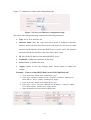
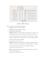
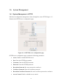
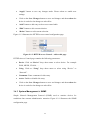
LevelOne User Manual WAB-7400 Dual Radio PoE Mesh Access Point Ver. 1.0.0-1021 Table of Content Table of Content 1 1 4 Introduction 1.1 1.2 1.3 1.4 1.5 1.6 1.7 1.8 2 3 Features & Benefits Package Contents Safety Guidelines WAB-7400 Description Mounting Install Guide System Requirements Applications Network Configuration 5 6 6 6 7 10 10 12 Understanding the Hardware 15 2.1 2.2 15 16 Hardware Installation IP Address Configuration LevelOne Mesh Web-based Interface 3.1 3.1.1 3.1.2 3.1.3 3.2 3.2.1 3.2.2 3.2.3 3.3 3.3.1 3.3.2 3.3.3 3.4 3.4.1 3.4.2 3.4.3 3.5 3.5.1 3.6 3.6.1 3.6.2 3.6.3 3.6.4 3.6.5 3.6.6 3.6.7 18 System 21 System > System..................................................................................................21 System > Advance ...............................................................................................22 System > Restart & Backup.................................................................................23 Network 26 Network > WLAN ...............................................................................................26 Network > WAN ..................................................................................................29 Network > Routing ..............................................................................................32 Security 34 Security > MSSID................................................................................................34 Security > MAC access .......................................................................................36 Security > VLAN.................................................................................................38 Services 40 Service > DHCP Relay ........................................................................................40 Service > System Watchdog ................................................................................42 Services > SSHD .................................................................................................42 QoS 44 QoS > WMM .......................................................................................................44 System Management 47 System Management > HTTPD...........................................................................47 System Management > SNMP.............................................................................48 System Management > SysLog Server ................................................................51 System Management > Firmware ........................................................................51 System Management > Trap ................................................................................52 System Management > Configuration .................................................................54 System Management > NMS Addresses..............................................................56 1 3.7 3.7.1 3.8 3.8.1 3.8.2 3.8.3 3.8.4 3.9 3.9.1 3.9.2 3.9.3 3.9.4 3.9.5 3.10 Login Setup 58 Login Setup > RADIUS.......................................................................................58 Tools 60 Tools > Ping.........................................................................................................60 Tools > Ifconfig ...................................................................................................60 Tools > Route.......................................................................................................61 Tools > TFTP .......................................................................................................62 Status 63 Status > System....................................................................................................63 Status > Interfaces................................................................................................63 Status > Services..................................................................................................64 Status > System Log ............................................................................................65 Status > Neighbor ................................................................................................65 Help 67 4 Appendix A – FCC Interference Statement 66 5 Appendix B – GPL Software Agreement 68 2 Revision History Revision 1.0 Date 2008-10-21 Remarks Initial Version 3 1 Introduction LevelOne WAB-7400 Dual Radio PoE Mesh AP is designed with IEEE802.11a/b/g standards and addressed on providing high performance mesh network. The product encased in the IP-65 protection enclosure and delivers the maximum scalability, high reliability at outdoor environment. Compared with expensive T1/E1 leased lines, the Mesh network offers a cost-effective last-mile connection. LevelOne WAB-7400 Dual Radio PoE Mesh AP provides wireless connection over self-adaptation mesh backhaul (5GHz). The mesh AP can operate at both 2.4GHz for long range and 5GHz to reduce the frequency interference. The detachable antenna design allows users to use various antennas for different deployment. The advanced OLSR (Optimal Link State Routing) protocol is the industry and scalable mesh routing algorithm. It allows data to be transferred with the optimal path. Included is WAN interface for Internet connection with Gateway mode; Power over Ethernet for both Gateway mode and Relay mode. LevelOne WAB-7400 Dual Radio PoE Mesh AP provides the highest security mechanism to protect data information over wireless. The security feature include AES backhaul link, WPA2 client access, SSL for web management. To simplify the administration task throughout the large area, this product also provides centralized management software. This software is built based on SNMP protocol and can be installed in computer. 4 1.1 Features & Benefits Features Benefits Dual Radio for independent Backhaul and local Allow operators to set up at both 2.4GHz for long access range and 5GHz to reduce the frequency interference. Self Configuration and Healing Automatically search and link with gateway AP and other nearest node Mesh AP for Ease of Deployment & Management LevelOne Business Class High Power Get more coverage and distance to save the installation Technology fee Lightning Protector in both antenna ports and Prevent a lightning stroke to damage the internal Ethernet port equipments Wide temperature range and robust mechanical Delivers reliable, top performance in the most design (IP65) demanding environments to Avoid water invaded and weather corroded Power over Ethernet (PoE) Easy installation and cost-effective OLSR protocol OLSR protocol provides optimized path of routing. Supports NAT (Network Address Shares single Internet account and provides a type of Translation)/NAPT firewall by hiding internal IP addresses for keeping hacker out Static Route Support Forwarding data in a network via a fixed path in multi-subnet Support Multiple SSID for client access mode Distinguish separate networks within the same wireless space to provide secure connection Support VLAN (Wired, Wireless) Reduce the size of each broadcast domain, which in turn reduces network traffic and increases network security Support 802.1x (EAP-TLS/TTLS/SIM/PEAP), Provide mutual authentication (Client and dynamic 802.11i (WPA/WPA2, AES), VPN pass-thru encryption keys to enhance security mechanisms Hide SSID Avoids unallowable users sharing bandwidth, increases efficiency of the network Support MAC Address access control list Ensures secure network connection Support WMM Extension Improve the user experience for audio, video, and voice applications by prioritizing data traffic Bandwidth control Enables operators to specify the maximum line bandwidth that a particular transfer operation can use Support SNMP v1/v2c/v3 Allow users to operate with existing network management tools Centralized management software Easy to manage volume Mesh AP via central control system to save the management cost 5 1.2 Package Contents Open the package carefully, and make sure that none of the items listed below are missing. Do not discard the packing materials, in case of return; the unit must be shipped in its original package. WAB-7400 Dual Radio PoE Mesh Access Point PoI-2000 Power over Ethernet Injector CD manual / Utility Mounting kit 1.3 Safety Guidelines In order to reduce the risk of fire, electric shock and injury, please adhere to the following safety guidelines. Carefully follow the instructions in this manual; also follow all instruction labels on this device. Except for the power adapter supplied, this device should not be connected to any other adapters. Do not spill liquid of any kind on this device. Do not place the unit on an unstable stand or table. This unit may drop and become damaged. Do not place any heavy objects on top of this unit. Do not use liquid cleaners or aerosol cleaners. Use a soft dry cloth for cleaning. 1.4 WAB-7400 Description WLAN 1 defined as ADHOC mode WLAN 2 defined as AP mode 6 1.5 Mounting Install Guide Make sure the following accessories are included in your WAB-7400 package. Option 1: Pole Mounting 7 Step 1: Fix the U type clip holder as picture 1 & 2. Step 2: Assemble the clip holder shown as 3~6. Step 3: Mount the WAB-7400 equipped with the holder on the pole shown as 7~9. 8 Option 2: Pole Mounting Step 1: Fix the U type clip holder as picture 1~5. Step 2: Equip the metal plate on the bottom case of WAB-7400 shown as 6. 9 Step 3: Assemble the holder to the bottom enclosure shown as 7. Step 4: Mount the WAB-7400 equipped with the holder on the pole shown as 8~9. Option 3: Wall Mounting Screws 1.6 System Requirements The following are the minimum system requirements in order configure the device. PC/AT compatible computer with a Ethernet / Wireless interface. Operating system that supports HTTP web-browser 1.7 Applications The wireless LAN products are easy to install and highly efficient. The following list describes some of the many applications made possible through the power and 10 flexibility of wireless LANs: a) Difficult-to-wire environments There are many situations where wires cannot be laid easily. Historic buildings, older buildings, open areas and across busy streets make the installation of LANs either impossible or very expensive. b) Temporary workgroups Consider situations in parks, athletic arenas, exhibition centers, disaster-recovery, temporary offices and construction sites where one wants a temporary WLAN established and removed. c) The ability to access real-time information Doctors/nurses, point-of-sale employees, and warehouse workers can access real-time information while dealing with patients, serving customers and processing information. d) Frequently changed environments Show rooms, meeting rooms, retail stores, and manufacturing sites where frequently rearrange the workplace. e) Small Office and Home Office (SOHO) networks SOHO users need a cost-effective, easy and quick installation of a small network. f) Wireless extensions to Ethernet networks Network managers in dynamic environments can minimize the overhead caused by moves, extensions to networks, and other changes with wireless LANs. g) Wired LAN backup Network managers implement wireless LANs to provide backup for mission-critical applications running on wired networks. h) Training/Educational facilities Training sites at corporations and students at universities use wireless connectivity to ease access to information, information exchanges, and learning. 11 1.8 Network Configuration To better understand how the wireless LAN products work together to create a wireless network, it might be helpful to depict a few of the possible wireless LAN PC card network configurations. The wireless LAN products can be configured as: a) Ad-hoc (or peer-to-peer) for departmental or SOHO LANs. b) Infrastructure for enterprise LANs. c) Wi-Fi Mesh Networks a) Ad-hoc (peer-to-peer) Mode This is the simplest network configuration with several computers equipped with the PC Cards that form a wireless network whenever they are within range of one another. In ad-hoc mode, each client is peer-to-peer, would only have access to the resources of the other client and does not require an access point. This is the easiest and least expensive way for the SOHO to set up a wireless network. The image below depicts a network in ad-hoc mode. b) Infrastructure Mode The infrastructure mode requires the use of an access point (AP). In this mode, all wireless communication between two computers has to be via the AP. It doesn’t matter if the AP is stand-alone or wired to an Ethernet network. If used in stand-alone, the AP can extend the range of independent wireless LANs by acting as a repeater, which effectively doubles the distance between wireless stations. depicts a network in infrastructure mode. 12 The image below c) Wi-Fi Mesh Networks A Wireless Mesh Network constructed from WiFi Technology alleviates a number of roaming challenges from laptops, IP phones, PDAs, and IP base devices: No geographical limitations – User can take a handheld or laptop computer anywhere without losing the connection in their home No physical connection required – Mobile IP connects automatically and obtains local IP router information Supports security – Authentication is performed to ensure that rights are being protected Access Anytime, Anywhere – Network access is assured at all times and from all locations. No missed E-mails and increase productivity due to constant connectivity. Emergencies – Rapidly deployable and robust communications between each member when emergencies are involved in difficult operations inside buildings, towers, or surrounded in forest fires Military Usage – Soldiers in a battlefield are exchanging information about their position and giving and receiving orders, or the instructions 13 14 2 Understanding the Hardware 2.1 Hardware Installation a) Plug one end of the Ethernet cable into the AP port of the PoE Injector and the other end into the Bridge/AP. b) Place one end of another Ethernet cable into the Network port of the PoE injector and another end into your PC/Notebook. c) Insert the DC-inlet of the power adapter into the port “DC-IN” and the other end into the power socket on the wall. d) The DHCP server function is enabled on the device, and your PC will receive an IP address from the device. Ensure that the TCP/IP settings on your computers are configured as Obtain IP address automatically. e) Place the unit in an appropriate place after conducting a site survey. Refer to the mounting instructions in the user’s manual. 15 This diagram depicts the hardware configuration 2.2 IP Address Configuration This device can be configured as a Bridge or Access Point. The default IP address of the device is 192.168.0.1. In order to log into this device, you must first configure the TCP/IP settings of your PC/Notebook. a) In the control panel, double click Network Connections and then double click on the connection of your Network Interface Card (NIC). You will then see the following screen. b) Select Internet Protocol (TCP/IP) and then click on the Properties button. This will allow you to configure the TCP/IP settings of your PC/Notebook. 16 c) Select Internet Protocol (TCP/IP) and then click on the Properties button. This will allow you to configure the TCP/IP settings of your PC/Notebook. d) Select Use the following IP Address radio button and then enter the IP address and subnet mask. Ensure that the IP address and subnet mask are on the same subnet as the device. For Example: Device IP address: 192.168.0.1 PC IP address: 192.168.0.10 PC subnet mask: 255.255.255.0 e) Click on the OK button to close this window, and once again to close LAN properties window. 17 3 LevelOne Mesh Web-based Interface Web-based configuration interface is accessible with computer with TCP/IP capability and web browser (e.g. Mozilla or IE).To access web-based configuration interface, enter https://192.168.0.1/. In the browser URL/Location field. You will see an authentication page display as shown in Figure 3.1.1. Figure 3.1.1: Windows authentication page Type “admin” in User Name and Password field, then click OK button. 18 LevelOne Mesh page has nine main menus: System, Network, Security, Services, QoS, System Management, Login Setup, Tools and Status. Each main menu also will have its submenu. System System System settings Advance Advance tuning Restart & Backup Restart & Backup settings Network WLAN WLAN settings WAN WAN settings Routing Routing settings Security MSSID MSSID settings MAC Access Filter MAC address VLAN VLAN settings Services DHCP Relay DHCP relay settings System Watchdog System watchdog settings SSHD SSHD Configuration WMM WMM settings QoS System Management 19 HTTPD Internal webserver settings SNMP SNMP settings Syslog Server Syslog Server settings Firmware Firmware maintenance Trap Trap settings Configuration Configuration management NMS Addresses Network Management System notifying settings. Login Setup RADIUS RADIUS settings Tools Ping Ping Ifconfig Ifconfig Route Route TFTP TFTP Status System System status Interfaces Interfaces statistics Services Services status System Log System logging Neighbor Mesh node status Help 20 3.1 System 3.1.1 System > System WAB-7400 is a layer 2 mesh network that supports gateway and relay operation mode. Figure 4.1.1 illustrates the system information configuration page. Figure 4.1.1: System Information Configuration page System Information Configuration page contains the following parameters: Name: Name of the device. Location: Location name that device located. Contact Name: Name of the contact person for consulting about the device. Contact Email: Email address of the contact person. Contact Phone: Phone number of the contact person. Description: Description of the device. Object ID: Display SNMP MIB object identification (OID) of the device. Operation Mode: Type of operation mode such as “Layer 2 Gateway” & “ Layer 2 Relay” “Save Changes” button to save any changes made. New settings are active after the device reboot. 21 3.1.2 System > Advance In this advance feature, networking conntrack and some wireless fine tune done. Figure 4.2.1 illustrates the advance configuration page. Figure 4.2.1: Advance configuration page Advance configuration has the following parameters: Maximum Session: maximum connection tracking session, a higher value is desired to support large number of local users. Generic Timeout: generic timeout for a connection tracking instance ICMP Timeout: ICMP timeout TCP Close Timeout: TCP close timeout TCP Close Wait Timeout: TCP close wait timeout TCP Established Timeout: TCP established timeout 22 TCP Finished Wait Timeout: TCP finished wait timeout TCP Last Ack Timeout: Last acknowledgement timeout TCP SYN Receive Timeout: TCP SYN receive timeout TCP SYN Sent Timeout: TCP SYN sent timeout TCP Time Wait Timeout: TCP Time wait timeout UDP Timeout: UDP timeout UDP Stream Timeout: UDP stream timeout Radio 1 distance: Desired operating distance for radio 1 ( usually refer to mesh radio ) Radio 2 distance: Desired operating distance for radio 2 ( usually refer to client access radio ) Regulatory Domain: Display the regulatory domain of the wireless interface Country: List of supported country available from the wireless interface. Outdoor Mode: Enable or disable use of outdoor mode on the wireless interface. External Channel Mode: Enable or disable use of external channel mode of the wireless interface “Save Changes” button to save any changes made. New settings are active after reboot. 3.1.3 System > Restart & Backup Under this configuration menu, you can perform the following action. Figure 4.3.1: Advance configuration page Backup: Click on the Backup button to begin. Save the file on your local disk by using the Save or Save to Disk button in the dialog box. 23 Figure 4.3.2: Advance configuration page Figure 4.3.3: Advance configuration page Click on the Reset link on the navigation drop-down menu. This option allows you to restore the device back to the factory default settings. Click on the Default button. Figure 4.3.4: Advance configuration page Click on the Restore link on the navigation drop-down menu. This option allows you to restore the configuration from a file that is stored on a local disk. 24 Figure 4.3.5: Configuration page Click on the Reboot link on the navigation drop-down menu. This option allows you to reboot the device in order for the current settings to take effect. 25 3.2 Network 3.2.1 Network > WLAN This device will form a wireless mesh network with other device provided the correct configuration. Figure 5.1.1 illustrates the wireless settings of the mesh. Figure 5.1.1: Network - WLAN configuration page MAC: Displays the MAC address of the wireless interface. Mode: WLAN 1 defined as ADHOC mode. ADHOC mode will bring the wireless device to adhoc mode where no AP is required. The connection is established for the duration of one session by discovering others device within range. WLAN 2 defined as AP mode. AP mode will bring the wireless device to Access Point mode. Under this mode, it can connect multiple wireless communication devices together to form a wireless network can relay data between wireless and wired devices. 26 Band: Select a wireless band from the drop-down list: 802.11a, 802.11b, or 802.11g. ESSID: The SSID is a unique named shared amongst all the points of the wireless network. The SSID must be identical on all points of the wireless network and cannot exceed 32 characters Frequency: Select a frequency/channel from the drop-down list. The channels available are based on the country’s regulation. A wireless network uses specific channels in the wireless spectrum to handle communication between clients. Some channels in your area may have interference from other electronic devices. Choose the clearest channel to help optimize the performance and coverage of your wireless network. Beacon Period: Beacons are packets sent by a wireless Access Point to synchronize wireless devices. Specify a Beacon Period value between 20 and 1000. The default value is set to 100 milliseconds. RTS Threshold: Packets over the specified size will use the RTS/CTS mechanism to maintain performance in noisy networks and preventing hidden nodes from degrading the performance. Specify a value between 1 and 65535. The default value is 2346. Fragment Threshold: Packets over the specified size will be fragmented in order to improve performance on noisy networks. Specify a value between 256 and 65535. The default value is 2346. DTIM Interval: A DTIM is a countdown informing clients of the next window for listening to broadcast and multicast messages. When the wireless Access Point has buffered broadcast or multicast messages for associated clients, it sends the next DTIM with a DTIM Interval value. Wireless clients detect the beacons and awaken to receive the broadcast and multicast messages. The default value is 1. Data rate: Select a data rate from the drop-down list or select auto. Diversity: A method for improving the reliability of a message signal by utilizing two or more communication channels with different characteristics, 27 in order to combat fading and interference. Click on “Diversity” drop down button to select “Card Default”, “Enable” or “Disable”. Tx Antenna: Click on “Tx antenna” drop down button to select “Diversity”, “Card Default”, “Port 1”, or “Port 2”. Rx antenna: Click on “Rx antenna” drop down button to select “Diversity”, “Card Default”, “Port 1”, or “Port 2” Base Datarate max Tx power: Default output power of the device. Current Datarate max Tx power: You may control the output power of the device by selecting a value from the drop-down list. Security: You may select WEP or WPA security. WEP is an acronym for Wired Equivalent Privacy, and is a security protocol that provides the same level of security for wireless networks as for a wired network. WEP is not as secure as WPA encryption. To gain access to a WEP network, you must know the key. The key is a string of characters that you create. When using WEP, you must determine the level of encryption. The type of encryption determines the key length. 128-bit encryption requires a longer key than 64-bit encryption. Keys are defined by entering in a string in HEX (hexadecimal - using characters 0-9, A-F) or ASCII (American Standard Code for Information Interchange - alphanumeric characters) format. ASCII format is provided so you can enter a string that is easier to remember. The ASCII string is converted to HEX for use over the network. Encryption Key: Specify the WEP encryption key. WPA Security: You may select WEP or WPA security. WPA (Wi-Fi Protected Access) was designed to improve upon the security features of WEP (Wired Equivalent Privacy). The technology is designed to work with existing Wi-Fi products that have been enabled with WEP. WPA provides improved data encryption through the Temporal Integrity Protocol (TKIP), which scrambles the keys using a hashing algorithm and by adding an integrity checking feature which makes sure that keys haven’t been tampered with. WPA Type: The encryption algorithm used to secure the data communication. 28 TKIP (Temporal Key Integrity Protocol) provides per-packet key generation and is based on WEP. AES (Advanced Encryption Standard) is a very secure block based encryption. Note that, if the bridge uses the AES option, the bridge can associate with the access point only if the access point is also set to use only AES. The device negotiates the cipher type with the access point, and uses AES when available. 802.1x: This option works with a RADIUS Server to authenticate wireless clients. Wireless clients should have established the necessary credentials before attempting to authenticate to the Server through this Gateway. Furthermore, it may be necessary to configure the RADIUS Server to allow this Gateway to authenticate users. Encryption Key: Specify the WPA encryption key. Click on the Save Changes button to store and changes and then reboot the device in order for the changes to take effect. 3.2.2 Network > WAN Figure 5.2.1 illustrates the network configuration page. Figure 5.2.1: Network configuration page Network contains the following parameters: Primary DNS: Primary Domain Name Server used to translates domain names to IP addresses. Edit this field to match your ISP DNS address or leave it unchanged to use received DNS address from your ISP. Secondary DNS: Secondary Domain Name Server used to translates domain names to IP addresses. A backup DNS address to primary DNS. Specify the 29 Secondary DNS address. Domain: Specify the Domain name of network. Gateway: IP address of router or nodes that serves as an entrance to another network, and vice-versa. Edit this field to match your ISP settings or leave it unchanged to use defaults from your ISP. “Save Changes” button to save any changes made. New settings are active after the device reboot. Network Time Protocol (NTP) is a protocol for synchronizing the system clocks over data networks. Figure 5.2.2 illustrates the NTP configuration page. Figure 5.2.2: NTP configuration page NTP configuration page contains the following parameters: Active: Enable or disable NTP feature Time Zone: Select the correct time zone. “Save changes” button to save any changes made. “Add” button to add new entry to the NTP. “Edit” button to edit current selection. “Delete” button to delete current selection. Figure 5.2.3 illustrates the configuration page for add or edit NTP server settings. 30 Figure 5.2.3: NTP – add or edit page NTP add or edit page contains the following parameters: Server: Specify the name of IP address of the NTP server. Min Poll: Specify the minimum number of times that the device should poll the server. Max Poll: Specify the maximum number of times that the device should poll the server. Comments: You may include comments or a description. Active: Choose to enable or disable the NTP Server entry. Click on the Save Changes button to store and changes and then reboot the device in order for the changes to take effect. 31 3.2.3 Network > Routing Routing refers to selecting paths in a network along which to send data. Figure 5.3.1 illustrates the route configuration page. Figure 5.3.1: Routing configuration page Route contains the following parameters: Routes List: Display list of routes. “Add” button to add new entry to the routes. “Edit” button to edit current selection. “Delete” button to delete current selection. Figure 5.3.2 illustrates the add or edit page for route entry. Figure 5.3.2: Routing – add or edit page Routes – add page contain the following parameter: Subnet: Enter the IP address of destination subnet. Netmask: Enter the IP address of destination subnet network mask. Direct: Click on “Direct” drop down menu to select “Direct” or “Indirect” route. Device: Click on “Device” drop down menu to select device. For example, MESH, VLAN0, VLAN1…… 32 Comments: Enter the interface comments. Active: Enable to disable this interface. “Save Changes” button to save any changes made. Please reboot to enable new settings. 33 3.3 Security 3.3.1 Security > MSSID In this section you may configure the SSID, beacon interval, RTS threshold, fragmentation threshold, DTIM interval, data rate, security type, and 802.1x. Figure 6.2.1 and Figure 6.2.2 illustrate the MSSID configuration page. Figure 6.1.1: MSSID configuration page Click on the Edit button to modify the default values. Figure 6.1.2: MSSID configuration page ESSID: The SSID is a unique named shared amongst all the points of the wireless network. The SSID must be identical on all points of the wireless network and cannot exceed 32 characters. Broadcast SSID: Select enable (visible) or disable (invisible). This is the SSID broadcast feature. When this option is set to Visible, your wireless network name is broadcast to anyone within the range of your signal. If you're not using encryption then they could connect to your network. When Invisible 34 mode is enabled, you must enter the Wireless Network Name (SSID) on the client manually to connect to the network. Beacon Interval: Beacons are packets sent by a wireless Access Point to synchronize wireless devices. Specify a Beacon Period value between 20 and 1000. The default value is set to 100 milliseconds. RTS Threshold: Packets over the specified size will use the RTS/CTS mechanism to maintain performance in noisy networks and preventing hidden nodes from degrading the performance. Specify a value between 1 and 65535. The default value is 2346. Fragment Threshold: Packets over the specified size will be fragmented in order to improve performance on noisy networks. Specify a value between 256 and 65535. The default value is 2346. DTIM Interval: A DTIM is a countdown informing clients of the next window for listening to broadcast and multicast messages. When the wireless Access Point has buffered broadcast or multicast messages for associated clients, it sends the next DTIM with a DTIM Interval value. Wireless clients detect the beacons and awaken to receive the broadcast and multicast messages. The default value is 1. Valid settings are between 1 and 255. Data rate: Select a transmission rate from the drop-down list. It is recommended to use the automatic option. Security: Select WEP or WPA (1&2) WEP is an acronym for Wired Equivalent Privacy, and is a security protocol that provides the same level of security for wireless networks as for a wired network. WEP is not as secure as WPA encryption. To gain access to a WEP network, you must know the key. The key is a string of characters that you create. When using WEP, you must determine the level of encryption. The type of encryption determines the key length. 128-bit encryption requires a longer key than 64-bit encryption. Keys are defined by entering in a string in HEX (hexadecimal - using characters 0-9, A-F) or ASCII (American Standard Code for Information Interchange - alphanumeric characters) format. ASCII 35 format is provided so you can enter a string that is easier to remember. The ASCII string is converted to HEX for use over the network. Four keys can be defined so that you can change keys easily. A default key is selected for use on the network. WPA (Wi-Fi Protected Access) was designed to improve upon the security features of WEP (Wired Equivalent Privacy). The technology is designed to work with existing Wi-Fi products that have been enabled with WEP. WPA provides improved data encryption through the Temporal Integrity Protocol (TKIP), which scrambles the keys using a hashing algorithm and by adding an integrity checking feature which makes sure that keys haven’t been tampered with. WPA Type: The encryption algorithm used to secure the data communication. TKIP (Temporal Key Integrity Protocol) provides per-packet key generation and is based on WEP. AES. Use AES only. AES (Advanced Encryption Standard) is a very secure block based encryption. Note that, if the bridge uses the AES option, the bridge can associate with the access point only if the access point is also set to use only AES. TKIP and AES. The bridge negotiates the cipher type with the access point, and uses AES when available. 802.1x: Select true of false from the drop-down list to enable or disable 802.1x. Click on the Save Changes button to store and changes and then reboot the device in order for the changes to take effect. 3.3.2 Security > MAC access MAC Access provides another level of security by filtering the packets coming into the device. Figure 6.2.1 and Figure 6.2.2 illustrate the MAC Access configuration page. 36 Figure 6.2.1: MAC access configuration page Active: Choose to enable or disable the MAC address filter feature. Type: Choose to allow or deny access for the MAC addresses. Click on the Save Changes button to store and changes and then reboot the device in order for the changes to take effect. MAC Access List: Click on the Add button to insert a MAC address. Figure 6.2.2: MAC access configuration page MAC: Specify the MAC address. Type: Select Allow or Deny. Comments: You may include comments or a description. Active: Choose to enable or disable the filter on this MAC address. Click on the Save Changes button to store and changes and then reboot the device in order for the changes to take effect. 37 3.3.3 Security > VLAN A Virtual LAN is a network of computers that behave as if they are connected to the same wire even though they may actually be physically located on different segments of a LAN. VLANs are configured through software rather than hardware, which make them extremely flexible. One of the biggest advantages of VLANs is that when a computer is physically moved to another location, it can stay on the same VLAN without any hardware reconfiguration. Figure 6.3.1 and Figure 6.3.2 illustrate the VLAN configuration page. Figure 6.3.1: VLAN configuration page Click on the Edit button to modify the existing VLAN. Figure 6.3.2: VLAN configuration page ID: Specify the VLAN tag ID. Type: Select the VLAN type from the drop-down list. IP: Specify the IP address for the VLAN tag. 38 Netmask: Specify the subnet mask for the IP address. Routed: Select if the VLAN is routed through the routing table or NAT. Comments: You may include comments or a description. Active: Choose to enable or disable this VLAN entry. Click on the Save Changes button to store and changes and then reboot the device in order for the changes to take effect. 39 3.4 Services 3.4.1 Service > DHCP Relay For a dynamic network, WAB-7400 is able to forward the DHCP request to a backend DHCP server when operating in layer 2 mode. Figure 7.1.1 illustrates the configuration page for DHCP Relay. Figure 7.1.1 DHCP Relay Settings DHCP Relay contains the following parameters: Active: Enable or disable DHCP Relay feature. Port: Port to listen for DHCP packet. Default value is 67. Hop count: Number of hop the DHCP discover packet can travel before it is dropped by this device. Default value is 10. Max packet size: Maximum packet size of the DHCP discover packet. Normally specify a large number of packet size is recommended. Default value is 1400. “Apply” button to save any changes made. Please reboot to enable new settings. “Modify” button to edit current selection. “Remove” button to delete current selection. “New Entry” button to add server IP or Interface. 40 Figure 7.1.2 illustrates to add or edit configuration page. Figure 7.1.2 Server or Interface configuration page. The add or edit configuration page contains the following parameters. Type: Server IP or interface list Interface Name: Once the “type” drop down menu is changed to interface, interface name selection drop down menu will appear for the users to make selection on the interface where the DHCP server can be reach. The interface also must include the interface where the client can be reach. IP: Specify the IP address of the backend DHCP server. Comments: Additional comments on this entry. Active Enable or disable this entry. “Apply” button to save any changes made. Please reboot to enable new settings. Example: How to setting DHCP Relay in the WAB-7400 Mesh AP? 1. Click “New Entry” button in the “DHCP Relay” page. 2. Select Type: ”Interface”, Interface Name: “VLAN0”, Comments: “DHCP Server MAC address”, Active: “Enable” and then click “Apply”. 3. Click “New Entry” button in the “DHCP Relay” page. 4. Select Type: “Server”, Server IP: “DHCP Server IP address”, Comments: “DHCP Server MAC address” and then click “Apply” button. 5. When finished the steps then reboot the WAB-7400 41 3.4.2 Service > System Watchdog Linux kernel watchdog will constantly monitor the integrity of the system. During system locked up, kernel watchdog will trigger a system reboot to recover the system from failure. Figure 7.2.1 illustrates the Linux kernel watchdog configuration page. Figure 7.2.1: System watchdog configuration page Linux kernel watchdog configuration page contains the following parameters: Active: Enable or disable this service. Interval: Specify the interval watchdog will pool for system status. Click on the Save Changes button to store and changes and then reboot the device in order for the changes to take effect. 3.4.3 Services > SSHD SSHD provides remote management using command line interface (CLI). Figure 7.3.1 illustrates the SSHD configuration page. Figure 7.3.1: SSHD configuration page 42 SSHD configuration page contains the following parameters: Active: Enable or disable this service. Port: Specify the TCP/IP port that the SSHD will listen for incoming connection. Click on the Save Changes button to store and changes and then reboot the device in order for the changes to take effect. 43 3.5 QoS 3.5.1 QoS > WMM Wireless Multimedia Extensions (WME), also known as Wi-Fi Multimedia (WMM) is a Wi-Fi Alliance interpretability certification, based on the IEEE 802.11e draft standard. It provides basic Quality of service (QoS) features to IEEE 802.11 networks. WMM prioritizes traffic according to 4 AC (Access Categories), however it does not provide guaranteed throughput. It is suitable for simple applications that require QoS, such as Wi-Fi Voice over IP (VoIP) phone. Figure 8.1.1 illustrates the WME configuration page. Figure 8.1.1: WME configuration page WME configuration page contains the following parameters: “Edit” button to edit the current selection of the active wireless interface list. Figure 8.1.2 illustrates the edit page for WME parameters. 44 Figure 8.1.2: WME - edit page WME – edit page contains the following parameters: Interface: Specify the interface for WMM. Comments: Optional comments for this entry. Active: Enable or disable WME. CWMIN: Minimum contention window. This parameter is input to the algorithm that determines the initial random backoff wait time (window) for retry of a transmission. The value specified here in the Minimum Contention Window is the upper limit (in milliseconds) of a range from which the initial random back off wait time is determined. a) Data type: Integer, in the range of 0 to 255 CWMAX: Maximum contention window. Maximum Contention Window. The value specified here in the Maximum Contention Window is the upper limit (in milliseconds) for the doubling of the random backoff value. a) Data type: Integer, in the range of 0 to 255 AIFS: The Arbitration Inter-Frame Spacing Number specifies a wait time (in milliseconds) for data frames. a) Data type: Integer, in the range of 0 to 255 45 TX OP LIMIT: Transmission Opportunity is an interval of time when a WME AP/station has the right to initiate transmissions onto the wireless medium (WM). This value specifies (in milliseconds) the Transmission Opportunity (TXOP); that is, the interval of time when the WMM AP/station as the right to initiate transmissions on the wireless network. a) Data type: Integer, in the range of 0 to 65535 ACM: Enable or disable Admission Control NO ACK POLICY: Enable or disable No-acknowledgement Best Effort: AP side, low priority, high throughput. Bulk data that requires maximum throughput and is not time-sensitive is sent to this queue. Best Effort (BSS): Station side, low priority, high throughput. Bulk data that requires maximum throughput and is not time-sensitive is sent to this queue. Background: AP side, medium priority, medium throughput and delay. Most traditional IP data is sent to this queue. Background (BSS): Station side, medium priority, medium throughput and delay. Most traditional IP data is sent to this queue. Video: AP side, high priority, minimum delay. Time-sensitive video data is automatically sent to this queue. Video (BSS): Station side, high priority, minimum delay. Time-sensitive video data is automatically sent to this queue. Voice: AP side, high priority. Time-sensitive data like VoIP and streaming media are automatically sent to this queue. Voice (BSS): Station side, high priority. Time-sensitive data like VoIP and streaming media are automatically sent to this queue. 46 3.6 System Management 3.6.1 System Management > HTTPD Web-based configuration management is done through the secure HTTP. Figure 9.1.1 illustrates the HTTPD server configuration page. Figure 9.1.1: HTTPD server configuration page HTTPD server configuration page contains the following parameters: Active: Enable or disable HTTPD server. Port: Enter the HTTPD port number. Username: Enter the HTTPD username. Password: Enter the HTTPD password. Reconfirm Password: Re-enter password to confirm it. Certificate Password: Enter the certificate password. Reconfirm Certificate Password: Re-enter certificate password to confirm it. Access Control: Enable or disable access control. 47 “Apply” button to save any changes made. Please reboot to enable new settings. Click on the Save Changes button to store and changes and then reboot the device in order for the changes to take effect. “Add” button to add entry to the access control table. “Edit” button to edit current selection. “Delete” button to edit current selection. Figure 9.1.2 illustrates the HTTPD access control configuration page. Figure 9.1.2: HTTPD Access Control – add or edit page HTTPD Access Control page contains the following parameters: Device: Click on “Device” drop down menu to select device. For example WAN, MESH, VLAN0…… Using: Click on “Using” drop down menu to select using “Device” or “Network”. Comments: Enter comments for this entry. Active: Enable or disable this entry. Click on the Save Changes button to store and changes and then reboot the device in order for the changes to take effect. 3.6.2 System Management > SNMP Simple Network Management Protocol (SNMP) used to monitor devices for conditions that warrant administrative attention. Figure 9.2.1 illustrates the SNMP configuration page. 48 Figure 9.2.1: SNMP configuration page SNMP configuration page contains the following parameters: Active: Enable or disable SNMP management. Version: Select “v1 or v2c”, “v3”, or “all” SNMP version. Port: Enter the SNMP port number. v2 Read Community: Enter the v2 Read Community. Reconfirm v2 Read Community: Re-enter v2 Read Community to verify. v2 Read-write Community: Enter the v2 Read-write Community. Reconfirm v2 Read-write Community: Re-enter v2 Read-write Community for verification. 49 v3 Read Username: Enter the v3 Read Username. v3 Read-write Username: Enter the v3 Read-write Username. v3 Password: Enter the v3 Password. Reconfirm v3 Password: Re-enter v3 Password for verification. v3 Passphrase: Enter the v3 Passphrase. Reconfirm v3 Passphrase: Re-enter v3 Passphrase for verification. Access control: Enable or disable SNMP access control. Click on the Save Changes button to store and changes and then reboot the device in order for the changes to take effect. “Add” button to add entry to the access control table. “Edit” button to edit current selection. “Delete” button to edit current selection. The default value for SNMP: V2 Read Community: public V2 Read-Write Community: Private V3 Read Username: snmpv3rouser V3 Read-Write Username: snmpv3rwuser Password: snmpv3password Passphrase: snmpv3passphrase Figure 9.2.2 illustrates the access control configuration page for SNMP. Figure 9.2.2: SNMP Access Control – add or edit page SNMP Access Control: add or edit page contains the following parameters: 50 Device: Click on “Device” drop down menu to select device. For example, WAN, MESH, VLAN0…… Using: Click on “Using” drop down menu to select “Device” or “Network”. Comments: Enter comments for this entry. Active: Click on “Active” drop down menu to enable or disable this entry. Click on the Save Changes button to store and changes and then reboot the device in order for the changes to take effect. 3.6.3 System Management > SysLog Server This device can automatically send system logs to a SysLog server. On this page you may configure the SysLog notice and server IP address. Figure 9.3.1 illustrates the Syslog server configuration page. Figure 9.3.1: SysLog Server configuration page Active: Choose to enable or disable this feature. Klog: Choose to enable or disable this feature. Level: Select a logging level from the drop-down list. Remote Syslog: Choose enable to remotely control the syslog feature. Remote Server Address: Specify the IP address of the remote syslog server. Click on the Save Changes button to store and changes and then reboot the device in order for the changes to take effect. 3.6.4 System Management > Firmware Click on the Firmware link in the navigation menu. This page allows you to upgrade the firmware of the device in order to improve the functionality and performance. 51 This page also displays the current firmware version and its release date. Figure 9.4.1 illustrates the Firmware upgrade configuration page. Figure 9.4.1: Firmware configuration page Ensure that you have downloaded the appropriate firmware from the vendor’s website. Click on the Browse button to select the firmware and then click on the Upload button. Note: Please do not power off the device during the firmware upgrade as they may cause permanent damage to the device. 3.6.5 System Management > Trap Trap used to report an alert or other asynchronous event about managed system. Figure 9.5.1 illustrates the trap configuration page. 52 Figure 9.5.1: Trap configuration page Trap configuration page contains the following parameters: Active: Enable or disable trap report. Configuration: Enable or disable report on configuration issue. Security: Enable or disable security trap report. Wireless: Enable or disable wireless trap report. Operational: Enable or disable operational trap report. Flash: Enable or disable flash trap report. Tftp: Enable or disable tftp trap report. Image: Enable or disable image trap report. Auth failure: Enable or disable authentication failure trap report. Click on the Save Changes button to store and changes and then reboot the device in order for the changes to take effect. “Add” button to add entry to trap server list. “Edit” button to edit current selection. 53 “Delete” button to edit current selection. Figure 9.5.2 illustrates the configuration page for add or delete trap server. Figure 9.5.2: Trap server – add or edit page Trap server: add or edit page contain the following parameter: IP: Enter destination IP to send trap. Community: Enter community of trap. Reconfirm Community: Re-enter community to confirm it. Version: SNMP Version. Comments: Enter Trap comments. Active: Enable or disable this entry. Click on the Save Changes button to store and changes and then reboot the device in order for the changes to take effect. 3.6.6 System Management > Configuration Click on the Configuration link in the navigation menu This section allows you to upload a web-certificate to the device and manage the IPSec, RSA, and X509 certificates. Figure 9.6.1 illustrates the system configuration page for uploading a web-certificate. 54 Figure 9.6.1: Configuration – Upload new webserver page Upload New Webserver Certificate: Click on the Browse button to select the certificate and then click on the Upload button. Manage RSA: Click on the Manage RSA button to upload a private RSA key. Figure 9.6.2 illustrates the Manage RSA configuration page. Figure 9.6.2: Configuration – Manage RSA page Upload Key-Pair: Click on the Browse button to select the certificate and then click on the Upload button. Manage X509: Click on the Manage X509 button to upload a local and remote certificate from the CA (Certification Authority). Figure 9.6.3 illustrates the Manage X509 configuration page. 55 Figure 9.6.3: Configuration – Manage X509 page Local Certificate: Click on the Browse button to select the certificate and then click on the Upload button. Remote Certificate: Click on the Browse button to select the certificate and then click on the Upload button. 3.6.7 System Management > NMS Addresses NMS address is used for the system to report back to Network Management System located outside of the network. Figure 9.7.1 illustrates the NMS server address configuration page. Figure 9.7.1 NMS Address List 56 NMS address configuration page contains the following parameters: NMS Address List: List of NMS server. “Add” button to add entry to the NMS address list. “Edit” button to edit current selection. “Delete” button to edit current selection. Click on the Save Changes button to store and changes and then reboot the device in order for the changes to take effect. Figure 9.7.2 illustrates the NMS address configuration page for add or edit. Figure 9.7.2: NMS Addresses – add or edit page NMS Address: add page contain the following parameter: Address: Enter the IP address of the NMS server. Port: Enter the port of the NMS server which is waiting for the report. Interval: Enter the interval of report to NMS server. Comments: Enter comments for the entry. Active: Enable or disable this entry. Click on the Save Changes button to store and changes and then reboot the device in order for the changes to take effect. 57 3.7 Login Setup 3.7.1 Login Setup > RADIUS Remote Authentication Dial In User Service (RADIUS) is an AAA (Authentication, Authorization and Accounting) protocol for applications such as network access or IP mobility. RADIUS client will verify authentication push by RADIUS server. Figure 10.1.1 illustrates the RADIUS client configuration page. Figure 10.1.1: RADIUS client configuration page RADIUS client configuration page contains the following parameters : Active: Enable or disable RADIUS client. NAS ID: Enter the NAS ID. Called Station ID: Enter the Called Station ID. NAS Port: Enter the NAS Port number. NAS Port Type: Enter the NAS Port Type. Interim Update Interval: Enter the value of Interim Update Interval. “Add” button to add entry to the RADIUS server list. 58 “Edit” button to edit current selection. “Delete” button to edit current selection. Click on the Save Changes button to store and changes and then reboot the device in order for the changes to take effect. Figure 10.1.2 illustrates the add or edit page for RADIUS entry. Figure 10.1.2: RADIUS server – add or edit page RADIUS server: add or edit page contain the following parameter: Server Name: Enter the RADIUS server name. Server Type: Click on “Server Type” drop down menu to select “Authenticate” or “Accounting” server type. Server Port: Enter the number of Server Port. Server Secret: Enter the Server Secret. Reconfirm Server Secret: Re-enter the Server Secret to confirm it. Comments: Enter RADIUS server comments. Active: Enable or disable this entry. Click on the Save Changes button to store and changes and then reboot the device in order for the changes to take effect. 59 3.8 Tools 3.8.1 Tools > Ping Figure 11.1.1 illustrates the ping page. Figure 11.1.1: Ping page Ping page contains the following parameters: Ping: Enter the IP address to ping. Number of pings: Enter the number of pings to send. “Ping” button to ping and display output of ping command. “Output” text area display result of the ping command. 3.8.2 Tools > Ifconfig Ifconfig page is used to collect verbose information about device network interfaces. Figure 11.2.1 illustrates the ifconfig page. 60 Figure 11.2.1: Ifconfig page Ifconfig page contains the following parameters: “Ifconfig” button to call ifconfig command. “Output” text area to display the output of the command. 3.8.3 Tools > Route Route page is used to collect information about device’s routing table. Figure 11.3.1 illustrates the route page. Figure 11.3.1: Route page Route page contains the following parameters: “Route” button to display output of route command. “Output” text area display result of the route command. 61 3.8.4 Tools > TFTP Figure 11.4.1 illustrates the TFTP page. Figure 11.4.1: TFTP page TFTP contains the following parameters: TFTP to: Enter the destination IP address of remote TFTP server. Operation: Select “put”, “get” or “get and reboot” file to remote TFTP server. File Name: Enter the File Name to put or get. Type of File – Select “config”, “firmware”, “ipsec x509 local”, “ipsec x509 remote”, or “ipsec rsa” file. Execute button to perform directed action. 62 3.9 Status 3.9.1 Status > System Click on the Status link on the navigation drop-down menu. This option displays the system uptime, CPU speed, free RAM, and firmware version. Figure 12.1.1 illustrates the system status page. Figure 12.1.1: System Status page 3.9.2 Status > Interfaces Click on the Interfaces link on the navigation drop-down menu. This option displays the details of the WAN, MESH, and VLAN0 interface. Figure 12.2.1 illustrates the interface page. Active interface will be listed under the interface page. Figure 12.2.1: Interface page Click on the Get Details button for the WAN interface. This section displays the hardware MAC address, IP type, IP address, broadcast address, netmask, MTU, and Tx/Rx packet information. Figure 12.2.2 illustrates the WAN interface page. 63 Figure 12.2.2: WAN Interface page Click on the Get Details button for the MESH and VLAN0 interface. This section displays the hardware MAC address, IP type, IP address, broadcast address, netmask, MTU, and Tx/Rx packet information. On the wireless interface it displays the ESSID, 802.11 band, frequency, MAC address, data rate, tx output power, encryption key, and QoS. Figure 12.2.3 illustrates the MESH and VLAN0 interface page. Figure 12.2.3: MESH and VLAN0 Interface page 3.9.3 Status > Services Click on the Services link on the navigation drop-down menu. This option displays 64 the current status of the following services: NTP client, SSHD, SNMP server, Syslog server, and web servers. Figure 12.3.1 illustrates the status of each service running in the device. Figure 12.3.1: Services page 3.9.4 Status > System Log Click on the System Log link on the navigation drop-down menu. This option displays the list of events by date and time. Click on the Get Log button to view the output. Figure 12.4.1 illustrates the system log page. Figure 12.4.1: System Log page 3.9.5 Status > Neighbor Neighbor status page will show the mesh node status. It show neighbor with details such as rate, rssi, timeout. Figure 12.5.1 illustrates the neighbor status page. 65 Figure 12.5.1: Neighbor Status page Neighbor Status page contains the following parameters: List of Neighbors: display a list of connected neighbor. <View hyperlink>: display the MAC table of the selected entry. View All Macs: display all the MAC currently visible to the device. 66 3.10 Help Help page provide links to specific help related to configuration and some description according to each submenu of the configuration. 67 4 Appendix A – FCC Interference Statement Federal Communication Commission Interference Statement This equipment has been tested and found to comply with the limits for a Class B digital device, pursuant to Part 15 of the FCC Rules. These limits are designed to provide reasonable protection against harmful interference in a residential installation. This equipment generates uses and can radiate radio frequency energy and, if not installed and used in accordance with the instructions, may cause harmful interference to radio communications. However, there is no guarantee that interference will not occur in a particular installation. If this equipment does cause harmful interference to radio or television reception, which can be determined by turning the equipment off and on, the user is encouraged to try to correct the interference by one of the following measures: Reorient or relocate the receiving antenna. Increase the separation between the equipment and receiver. Connect the equipment into an outlet on a circuit different from that to which the receiver is connected. Consult the dealer or an experienced radio/TV technician for help. FCC Caution: Any changes or modifications not expressly approved by the party responsible for compliance could void the user's authority to operate this equipment. This device complies with Part 15 of the FCC Rules. Operation is subject to the following two conditions: (1) This device may not cause harmful interference, and (2) this device must accept any interference received, including interference that may cause undesired operation. IMPORTANT NOTE: FCC Radiation Exposure Statement: This equipment complies with FCC radiation exposure limits set forth for an uncontrolled environment. This device complies with FCC RF Exposure limits set forth for an uncontrolled environment, under 47 CFR 2.1093 paragraph (d)(2). 66 This transmitter must not be co-located or operating in conjunction with any other antenna or transmitter. 67 5 Appendix B – GPL Software Agreement This product incorporates open source code into the software and therefore falls under the guidelines governed by the General Public License (GPL) agreement. Adhering to the GPL requirements, the open source code and open source license for the source code are available for free download at http://global.level1.com. If you would like a copy of the GPL or other open source code in this software on a physical CD medium, LevelOne (Digital Data Communications) offers to mail this CD to you upon request, for a price of US$9.99 plus the cost of shipping.