1
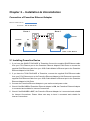
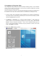
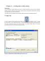
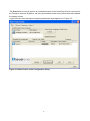
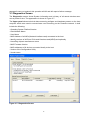
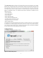
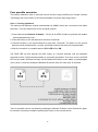
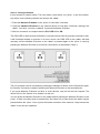
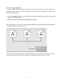
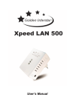
LevelOne
PLI-3510
200Mbps Powerline Adapter with Mains
Pass-Through
User Manual
Table of Contents
Chapter 1 – Introduction ................................................................................................................. 1
1.1 Overview ........................................................................................................................... 1
1.2 Specification ..................................................................................................................... 1
1.3 LED Indicators .................................................................................................................. 1
1.4 Package Contents .............................................................................................................. 1
1.5 System Requirements........................................................................................................ 1
Chapter 2 – Installation & Uninstallation ....................................................................................... 2
2.1 Installing Powerline Device .............................................................................................. 2
2.2 Installation of Powerline Utility........................................................................................ 3
2.3 Uninstallation of Configuration Utility............................................................................. 7
3.1 Main Tab ........................................................................................................................... 8
3.2 Privacy Screen ................................................................................................................ 14
3.3 Diagnostics Screen .......................................................................................................... 15
3.4 About Screen ................................................................................................................... 16
Chapter 4 – Reset and Network ID Buttons Setting ..................................................................... 17
4.1 Reset Button .................................................................................................................... 17
4.2 Network ID Button ......................................................................................................... 17
Chapter 1 – Introduction
1.1 Overview
The LevelOne PLI-3510 operates on HomePlug AV standard, providing up to 200Mbps data
speed over the existing household power supply. This Product is cost-effective, easy to create a
home network without spending time and money to run expensive CAT5 cabling. Powerline
Device is the best solution for no-new-wire networking in the house or office.
1.2 Specification
- Standard: IEEE 1901 Broadband over Powerl / HomePlug Powerline Specification AV compliant
- Speed: up to 200Mbps
- Modulation: supports OFDM, 1024/256/64/16/8 QAM, QPSK, BPSK, and ROBO modulation
schemes.
- Frequency: 4.3 MHz ~ 20.9 MHz
- Security: 128-bits AES encryption
- IEEE802.3 10Base-T, IEEE802.3U 100Base-TX
1.3 LED Indicators
The Powerline Ethernet Adaptor has three LEDs indicator:
Turn on when connected to AC power supply.
Turn on when detected and connected with another HomePlug adaptor
within the network.
Turn on when connected to the Ethernet card of the computer or
Ethernet Hub / Switch.
1.4 Package Contents
Make sure that you have the following items:
- PLI-3510 200Mbps Powerline Adapter with Mains Pass-Through
- RJ-45 cable
- CD User Manual / Utility / QIG
- Quick Installation Guide
1.5 System Requirements
- Powerline Ethernet Adaptor can support any Operation System. But the Powerline Utility can
only support Windows 2000/XP/Vista/Windows 7.
- Pentium III 300 MHz or above
- Powerline device
- AC power outlet
1
Chapter 2 – Installation & Uninstallation
Connection of Powerline Ethernet Adapter
Ethernet Cable (RJ-45)
Powerline
Room 1
Room 2
Internet
Notebook
PC
ADSL / Cable Modem
2.1 Installing Powerline Device
1. If you have the SINGLE PACKAGE of Powerline,Connect the supplied RJ45 Ethernet cable
from your PC's Ethernet port to the Powerline Ethernet Adapter's LAN Ports or connect the
supplied RJ45 Ethernet cable from your xDSL/Cable Modem's Ethernet port to the Powerline
Ethernet Adapter's LAN Ports.
2. If you have the TWIN PACKAGE of Powerline, connect the supplied RJ45 Ethernet cable
from your PC's Ethernet port to the Powerline Ethernet Adapter's LAN Ports and connect the
supplied RJ45 Ethernet cable from your xDSL/Cable Modem's Ethernet port to the Powerline
Ethernet Adapter's LAN Ports.
3. Connect the Powerline Ethernet Adapter to your wall-mounted power outlet.
4. Check if the PLC LED of Powerline Ethernet Adapter is ON, the Powerline Ethernet Adapter
is connected and suitable for Internet Connections.
5. Check if the PLC LED is OFF, the Powerline Ethernet Adapter isn’t connected and suitable
for Internet Connections. Please follow next step to have it connected and suitable for
Internet Connections.
2
2.2 Installation of Powerline Utility
The Configuration Utility enables the users to identify HomePlug devices on the Powerline
network; measures data rate performance, ensures privacy and performs diagnostics by setting
user defined secure Powerline networks.
Users are requested to verify that no other Encryption Management Utilities are installed prior to
the installation of this utility. Other utilities should be uninstalled before installing this utility.
1. In order to install, insert Configuration Utility CD-ROM into the computer’s CD-ROM drive.
The program shall run automatically. Alternatively this can also be done manually by double
clicking the autorun.exe file on the CD.
2. For Windows 7 / Vista User only, for Security reasons Windows 7 / Vista requires the
installer program to have administrator privileges so the new policy called " User Account
Control " has been introduced in Windows 7 / Vista. If UAC is enabled Windows pops up a
window " User Account Control " Windows need your permission to continue. User needs
to click " Yes / Allow " to continue.
3. Please click “ Utility” button to continue.
3
4. Click “Setup” button to continue.
5. Click “Next” button to continue.
6. Click “I Agree & Next ” button to continue.
4
7. Click “Next ” button to continue.
8. Click “Close ” button to exit.
5
9. In order to start the utility, double-click the utility icon on desktop.
10. You can see your device working well. The top panel of the screen shot shows a Homeplug
device connected locally to your computer. The bottom panel shows one device connected
remotely to the computer running the utility.
6
2.3 Uninstallation of Configuration Utility
1. To uninstall the Configuration Utility, go to the “Control Panel” of your system.
2. Open the “Add/Remove Programs”.
3. Select and double click on the “Powerline Utility” in the Add/Remove Programs
Properties.
4. Follow the on screen instructions to uninstall the Powerline Utility.
7
Chapter 3 – Configuration Utility Setup
Introduction
The Configuration Utility enables the users to identify HomePlug devices on the powerline
network, measures data rate performance, ensures privacy and performs diagnostics by setting
user defined secure powerline networks.
The Utility will use a Graphical User Interface (GUI) with limited user selectable options.
3.1 Main Tab
In order to start the utility, double-click the utility icon
on desktop. Figure 3-1 shows
the main screen of the Configuration Utility. The top panel of the screen shot shows a HomePlug
AV device connected locally to the host computer. The bottom panel shows four devices
connected remotely to the computer running the utility.
Figure 3-1: Main Screen with HomePlug AV device Local
8
The Main screen provides a list of all powerline devices logically connected to the computer
when the utility is running.The top panel shows all local HomePlug devices connected to the
computer’s NIC (Network Interface Card). In most cases, only one device will be seen. In
situations where there are more than one local device being connected, such as a USB or an
Ethernet adapter, the user can select the local device by clicking on it and then click the Connect
button to its right. The status area above the button indicates that your PC is connected to that
same device. Once connected to the local device, the utility will automatically scan the power line
periodically for any other HomePlug devices. If no local HomePlug devices are discovered, the
status area above the connect button will indicate with a message ‘NO HOMEPLUG ADAPTERS
DETECTED’.
Figure 3-2 illustrates the presence of two local devices connected locally to the computer.
Figure 3-2: Multiple Local Device Connection
The lower panel displays all the HomePlug remote devices, discovered on the current logical
network. The total number of remote devices connected on the same network can be found on
top of the Remote device panel. The Network type (Public or Private) is also displayed based on
the network status of the local device. The scan status option is displayed on the top right corner
9
above the Remote devices panel showing whether the Autoscan functionality is turned ON or
OFF. The following information is displayed for all devices that appear in the lower panel.
Device Name column shows the default device name, which may be user re-defined. A user can
change the name by either using the rename button or by clicking on the name and editing
in-place. An icon is usually shown with the name. By default, the icon is always accompanied by
a device name.
MAC Address column shows the Remote device’s MAC address.
10
Password column by default is blank and ‘Enter Password’ button can be used to enter it.
To set the Password of the device (required when creating a private network), first select the
device by clicking on its name in the lower panel and then click on the Enter Password button. A
dialog box will appear as shown in Figure 3-3 to type the password. The selected device name is
shown above the password field and the password can be verified by hitting the OK button. The
Password field accepts the Device password in any case formats, with or without dashed
between them. If a device was not found, the user will be notified along with the suggestions to
resolve common problems. This process might take a few seconds to get completed.
Figure 3-3: Set Device Password
11
Add button is used to add a remote device to the existing network by entering the device
password of the device. A dialog box will appear as shown below in Figure 3-4. The dialog box
allows the user to enter both a device name and the password. If a device was not found, the
user will be notified and suggestions to resolve common problems will be presented.
Figure 3-4: Add Remote Device
Note: The device must be present on the power line (plugged in) in order for the password to be
confirmed and added to the network. If the device could not be located, a warning message will
be shown.
12
The Scan button is used to perform an immediate search of the HomePlug devices connected to
the Powerline network. By default, the utility automatically scans every few seconds and updates
the display screen.
A typical screen after naming and supplying passwords might appear as in Figure 3-5.
Figure 3-5: Main Screen of the Configuration Utility
13
3.2 Privacy Screen
The Privacy screen provides the user with an option to maintain security for their logical network
and also to select the devices that has to be included in the network. The appearance is shown in
Figure 3-6. All HomePlug devices are shipped using a default logical network (network name),
which is normally “HomePlugAV”. The Privacy dialog screen allows user to change to a private
network by changing the network name (network password) of devices.
The user can always reset to the HomePlug network (Public) by entering “HomePlugAV” as the
network name or by clicking on the “Use Default” button.
Note: Changing the network name to anything other than HomePlugAV will show the network
type on the main screen as Private.
Figure 3-6: Privacy Screen
The Set Local Device Only button can be used to change the network name (network password)
of the local device. If a new network password is entered, all the devices seen on the Main panel
prior to this will be no longer present in the new network, effectively making the local devices not
to communicate to the devices who were in the old logical network. Devices previously set up
with the same logical network (same network name) will appear in the device list afterward
selecting this option.
The Set All Devices button is used to change the logical network of all devices that appear on
the Main panel whose Device’s Password had been entered for the same logical network. A
dialog window will appear to report the success of this operation. For devices whose device
14
password’s were not entered, this operation will fail and will report a failure message.
3.3 Diagnostics Screen
The Diagnostics screen shows System information and a history of all remote devices seen
over a period of time. The appearance is shown in Figure 3-7.
The Upper panel shows technical data concerning software and hardware present on the host
computer which were used to communicate over HomePlug on the Powerline network. It shall
include the following:
- Operating System Platform/Version
- Host Network Name
- User Name
- MAC Address of all NICs (Network interface card) connected to the host
- Identify versions of all Driver DLLs and Libraries used (NDIS) and optionally
- HomePlug chipset manufacturer name
- MAC Firmware Version
- MAC addresses of all devices connected locally to the host
- Version of the Configuration Utility
- Vendor name
Figure 3-7: Diagnostics Screen
15
The Lower panel contains a history of all remote devices seen on the computer over a certain
period of time. All devices that were on the powerline network are listed here along with a few
other parameters. Devices that are active on the current logical network will show a transfer rate
in the Rate column; devices on other networks, or devices that may no longer exist are shown
with a “?” in the Rate column. The following remote device information is available from the
diagnostics screen:
- Device Alias Name
- Device MAC Address
- Device Password
- Device Last known rate
- Device Last Known Network name
- HomePlug chipset manufacturer name
- Date device last seen on the network
- MAC Firmware Version.
The diagnostics information displayed may be saved to a text file for later use, or can be printed
for reference for a technical support call. Devices, which are not part of the network anymore,
can be deleted using the delete button. A dialog window pops up with a confirmation message if
we try to delete a device whose password has been entered.
3.4 About Screen
The About screen shows the software version.
Figure 3-8: About dialog screen
16
Chapter 4 – Reset and Network ID Buttons Setting
There are 2 buttons on the device, one is Reset button the other is Network ID button.
4.1 Reset Button
Push this button can reset to the factory default settings. Be careful, when you press the reset
button, please remove the Ethernet cable (RJ-45cable) first, and then press the reset button.
After press the reset button for less than 3 seconds and then wait the PWR LED light again.
Don’t power off when the device is in reset process.
4.2 Network ID Button
The HomePlug AV powerline communication devices can form multiple logical networks over a
common powerline or coax medium. There are many situations when it is desirable to add new
devices to, or remove old devices from, a HomePlug AV logical network.
Push this button to accomplish using HomePlug AV Simple Connect Technology.
Network ID Button trigger state conditions
“Adder state” for a device providing the NMK for an existing AVLN
“Joiner state” for a device that will join an AVLN
Pushing buttons on any two devices results in one of them becoming an “adder” and the other
one a “joiner”
17
Four possible scenarios
This section describes how to add and remove devices using HomePlug AV Simple Connect
Technology and covers some of the technical details of how the technology works.
Case 1: Forming a Network
Two devices with different network membership key (NMK) values are connected to the same
powerline. The user wants them to form a logical network.
1. Press each device Network ID button > 10 sec till all LEDs re-flash to generate the random
network password key first.
2. Press the button on the first device for less than 3 seconds.
3. Press the button on the second device for less than 3 seconds. The button on the second
device must be pressed within 1 minute, by default however the interval is programmable.
4. Wait for connection to complete and the PLC LED will be ON.
The PWR LED on both devices will flash evenly at 1-second intervals until the operation
succeeds or fails. It will illuminate steadily on successful completion. If an error occurs, the PWR
LED on the ‘adder’ will flash unevenly until the Network ID button on the ‘adder’ is pressed again
or the ‘joiner’ is reset by holding the Network ID buttons down for more than 10 seconds.
The join operation can be cancelled by pressing the Network ID button on the first device again,
for less than 3 seconds, instead of pressing the button on the second device.
18
Case 2: Joining a Network
In this scenario a network exists. The user wants a new device, the ‘joiner’, to join the network.
Any device on the existing network can become the ‘adder’.
1. Press the Network ID button on the ‘joiner’ for less than 3 seconds.
2. Press the Network ID button on any network device for less than 3 seconds, making it the
‘adder’. You have 1 minute, by default, to press this Network ID button.
3. Wait for connection to complete and the PLC LED will be ON.
The PWR LED on both devices will flash at 1-second intervals until the process succeeds or fails.
It will illuminate steadily on success. If an error occurs, the PWR LED on the ‘adder’ will flash
unevenly until the Network ID button on the ‘adder’ is pressed again or the ‘joiner’ is reset by
pressing the Network ID button for more than 10 seconds, as described in Case 3:
The join operation can be cancelled by pressing the Network ID button on the first device again,
for less than 3 seconds, instead of pressing the Network ID button on the second device.
If you press Network ID buttons on three or more devices, only the first two will respond. The
others will not. See Case 4 for a variation on this rule.
You can press the Network ID button on the ‘adder’ before pressing the Network ID button on the
‘joiner’. It does not matter which is pressed first. See Case 4 for a case where the ‘adder’ may be
pressed before the ‘joiner’. Once a ‘joiner’ becomes a member of the network, it may become the
‘adder’ in the next join operation.
19
Case 3: Leaving a Network
A network exists. The user wants to remove one device, the ‘leaver’, from that network, for
whatever reason. He may want to remove the device from service altogether or have it join
another logical network.
1. Press the Network ID button on the ‘leaver’ for at least 10 seconds. The device will reset and
restart with a random NMK.
2. Wait for reset to complete and the PLC LED will be OFF.
The PWR LED on the ‘leaver’ will momentarily extinguish during reset, flash during restart then
illuminate steadily. No errors can occur.
Once the process completes, the user may disconnect the device from the medium or join it to
another logical network on the same medium, as described in either Case 1 or Case 3.
20
Case 4: Join Multiple Devices to a Network
To add several new devices to an existing network, the process in Case 2 must be repeated for
each ‘joiner’. A vendor may implement a mode of operation in which an ‘adder’ device in the
network remains in the adder state for an extended period allowing additional ‘joiners’ to be
added in turn. This lets you press the ‘adder’ Network ID button once then press each ‘joiner’
Network ID button in turn.
If Network ID buttons are pressed on two or more joiners, only the first one will respond. The
second will not. This makes timing important.
21