1
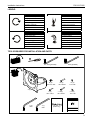
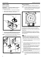
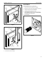
INSTALLATION INSTRUCTIONS
Instrucciones de instalación
Installationsanleitung
Instruções de Instalação
Istruzioni di installazione
Installatie-instructies
Instructions d´installation
Direct Attach Ceiling Mount
Spanish Product Description
German Product Description
Portuguese Product Description
Italian Product Description
Dutch Product Description
French Product Description
FHS110/ FHSV
FHS110/ FHSV
Installation Instructions
DISCLAIMER
CSAV, Inc., and its affiliated corporations and subsidiaries
(collectively, "CSAV"), intend to make this manual accurate and
complete. However, CSAV makes no claim that the information
contained herein covers all details, conditions or variations, nor
does it provide for every possible contingency in connection
with the installation or use of this product. The information
contained in this document is subject to change without notice
or obligation of any kind. CSAV makes no representation of
warranty, expressed or implied, regarding the information
contained herein. CSAV assumes no responsibility for
accuracy, completeness or sufficiency of the information
contained in this document.
IMPORTANT WARNINGS AND
CAUTIONS!
WARNING: A WARNING alerts you to the possibility of
serious injury or death if you do not follow the instructions.
CAUTION: A CAUTION alerts you to the possibility of
damage or destruction of equipment if you do not follow the
corresponding instructions.
2
WARNING: Failure to read, thoroughly understand, and
follow all instructions can result in serious personal injury,
damage to equipment, or voiding of factory warranty! It is the
installer’s responsibility to make sure all components are
properly assembled and installed using the instructions
provided.
WARNING: Failure to provide adequate structural strength
for this component can result in serious personal injury or
damage to equipment! It is the installer’s responsibility to
make sure the structure to which this component is attached
can support five times the combined weight of all equipment.
Reinforce the structure as required before installing the
component.
WARNING: Exceeding the weight capacity of the mount
can result in serious personal injury or damage to equipment!
It is the installer’s responsibility to make sure the combined
weight of the mount and all attached components does not
exceed 40lbs (18.14kg).
Installation Instructions
FHS110/ FHSV
LEGEND
Tighten Fastener
Phillips Screwdriver
Apretar elemento de fijación
Destornillador Phillips
Befestigungsteil festziehen
Kreuzschlitzschraubendreher
Apertar fixador
Chave de fendas Phillips
Serrare il fissaggio
Cacciavite a stella
Bevestiging vastdraaien
Kruiskopschroevendraaier
Serrez les fixations
Tournevis à pointe cruciforme
Сожмите Застежку
Отвертка
Loosen Fastener
Hex-Head Wrench
Aflojar elemento de fijación
Llave de cabeza hexagonal
Befestigungsteil lösen
Sechskantschlüssel
Desapertar fixador
Chave de cabeça sextavada
Allentare il fissaggio
Chiave esagonale
Bevestiging losdraaien
Zeskantsleutel
Desserrez les fixations
Clé à tête hexagonale
Ослабьте Застежку
Ключ с шестигранной головкой
TOOLS REQUIRED FOR INSTALLATION AND PARTS
5/32" (provided)
3/16" (provided)
B (2)
5/16-18 x 3/8"
**D (4)
M4 x 20mm
**F (4)
1/2" x 3/8"
A (1)
C (4)
M4 x 12mm
H (1)
3/16"
J (1)
5/32"
****E (4)
M4 x 30mm
****G (4)
1/2" x 3/4"
(FHSV only)
3
FHS110/ FHSV
Installation Instructions
INSTALLATION
Display Installation
1.
Mount Installation
IMPORTANT ! : The following installation instructions
assume that a 1 1/2" NPT pipe has been properly
installed and is in place.
1.
Thread mount (A) onto 1 1/2" NPT pipe until hand tight.
2.
Adjust mount (A) position until Centris cup is facing the
desired position of the display. (See Figure 1)
Determine mounting pattern on display. (See Figure 3)
NOTE: The mount is designed to accommodate both 75 x 75
and 100 x 100 VESA mounting patterns. If the display
being mounted has either of these mounting patterns
continue with display installation.
VESA 75 x75
VESA 100 x 100
1 1/2" NPT Pipe
1
Centris Cup
(A) x1
Figure 3
If the display does not have a 75 x75 or 100 x 100 VESA
mounting pattern, an interface bracket will be required. The
FHSV Series mount comes with a 200 x 100 interface bracket
(FSA4101 Kit).
Figure 1
3.
When mount (A) is properly positioned secure mount (A) to
1 1/2" NPT pipe by installing and tightening 5/16-18 x 3/8"
set screw using 3/16" hex wrench (H). (See Figure 2)
If the display being installed does not have any of the three
mounting patterns identified above, contact a Chief Customer
Service representative by calling 952-894-6280 or by visiting
www.chiefmfg.com.
NOTE: If mount is being used to couple two pipes, use both set
screws when securing mount (A) to pipes.
WARNING: IMPROPER INSTALLATION CAN LEAD TO
DISPLAY FALLING CAUSING SERIOUS PERSONAL
INJURY OR DAMAGE TO EQUIPMENT! DO NOT install
display without an approved interface bracket and hardware.
2.
(B) x 1
(A) x1
(B) x 1
2
2
or
3.
Install two Phillips pan head machine screws (C,D, or E) into
upper mounting holes in display back leaving 3/16" of screw
protruding out of display.
4.
Align screws in display back with upper mounting holes in
Centris cup and lower display until screws are seated in
lower area of mounting slots (100 x 100) or teardrop
mounting holes (75 x 75).
5.
Hold display so that display back is against Centris cup and
install two Phillips pan head machine screws (C,D, or E)
through lower mounting holes in Centris cup and into lower
mounting holes in display back.
(A) x1
(H) x 1
Install FSA4101 interface bracket, if required, following the
instructions provided with the kit.
NOTE: If the display has a recessed mounting surface spacers
Figure 2
4
(F or G) must be placed between display back and
Centris cup and longer screws must be used to secure
display.
Installation Instructions
FHS110/ FHSV
ADJUSTMENTS
To adjust display Roll, Pitch, and YAW tension:
1 1/2" NPT Pipe
Display
3
1.
Disconnect all wires and cable from the display.
2.
Remove two Lower screws securing display to Centris cup.
3.
Loosen two Upper screws securing display.
4.
Lift display upward and away from mount.
5.
Using a Phillips screwdriver turn the tension adjustment
screw clockwise to increase tension, or counter-clockwise
to decrease tension. (See Figure 6)
6.
Re-install display.
4
(C, D, or E) x 4
(A) x 1
Figure 4
1 1/2" NPT Pipe
Display
Figure 6
4
(C, D, or E) x 4
(A) x 1
Figure 5
6.
Route cables and wires to display.
5
FHS110/ FHSV
6
Installation Instructions
Installation Instructions
FHS110/ FHSV
7
FHS110/ FHSV
Installation Instructions
USA/International
Europe
Asia Pacific
8805-000219
©2007 Chief Manufacturing
www.chiefmfg.com
01/07
A
P
F
A
P
F
A
8401 Eagle Creek Parkway, Savage, MN 55378
800.582.6480 / 952.894.6280
877.894.6918 / 952.894.6918
Fellenoord 130 5611 ZB EINDHOVEN, The Netherlands
+31 40 2668620
+31 (0) 40 2668615
Room 30I, Block D, Lily YinDu International Building
LuoGang, BuJi Town, Shenzhen, CHINA. Post Code: 518112
P +86-755-8996 9226 ; 8996 9236 ; 8996 9220
F +86-755-8996 9217