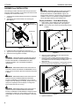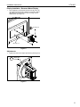
1
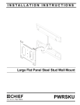
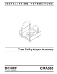
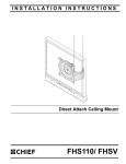
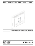
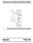
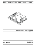
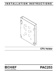
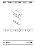
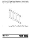
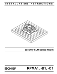
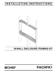
INSTALLATION INSTRUCTIONS
Array Centris Accessory
Spanish Product Description
German Product Description
Portuguese Product Description
Italian Product Description
Dutch Product Description
French Product Description
KTA1005
KTA1005
Installation Instructions
DISCLAIMER
Milestone AV Technologies, Inc., and its affiliated corporations
and subsidiaries (collectively, "Milestone"), intend to make this
manual accurate and complete. However, Milestone makes no
claim that the information contained herein covers all details,
conditions or variations, nor does it provide for every possible
contingency in connection with the installation or use of this
product. The information contained in this document is subject
to change without notice or obligation of any kind. Milestone
makes no representation of warranty, expressed or implied,
regarding the information contained herein. Milestone assumes
no responsibility for accuracy, completeness or sufficiency of
the information contained in this document.
Chief® and Centris™ are trademarks of Milestone AV
Technologies. All rights reserved.
IMPORTANT WARNINGS AND
CAUTIONS!
WARNING: A WARNING alerts you to the possibility of
serious injury or death if you do not follow the instructions.
CAUTION: A CAUTION alerts you to the possibility of
damage or destruction of equipment if you do not follow the
corresponding instructions.
WARNING: Failure to read, thoroughly understand, and
follow all instructions can result in serious personal injury,
damage to equipment, or voiding of factory warranty! It is the
installer’s responsibility to make sure all components are
properly assembled and installed using the instructions
provided.
WARNING: Failure to provide adequate structural strength
for the installation of this kit can result in serious personal
injury or damage to equipment! It is the installer’s
responsibility to make sure the structure to which this mount
is attached can support five times the combined weight of all
equipment.
WARNING: Exceeding the weight capacity can result in
serious personal injury or damage to equipment! See the
installation instructions that came with the array onto which
this accessory is being installed for weight limits. The
accessory’s weight capacity is 40 lbs (18.1 kg).
LEGEND
2
Tighten Fastener
Adjust
Apretar elemento de fijación
Ajustar
Befestigungsteil festziehen
Einstellen
Apertar fixador
Ajustar
Serrare il fissaggio
Regolare
Bevestiging vastdraaien
Afstellen
Serrez les fixations
Ajuster
Сожмите Застежку
Приспособьтесь
Loosen Fastener
Hex-Head Wrench
Aflojar elemento de fijación
Llave de cabeza hexagonal
Befestigungsteil lösen
Sechskantschlüssel
Desapertar fixador
Chave de cabeça sextavada
Allentare il fissaggio
Chiave esagonale
Bevestiging losdraaien
Zeskantsleutel
Desserrez les fixations
Clé à tête hexagonale
Ослабьте Застежку
Главный ведьмой Рывок
Installation Instructions
KTA1005
TOOLS REQUIRED FOR INSTALLATION AND PARTS
I/M
B (4)
M4 x 12mm
x1
C (4)
M4 x 20mm
D (4)
M4 x 30mm
A (1)
E (4)
.50 x .194 x .375
F (4)
.50 x .194 x .750
3
KTA1005
Installation Instructions
ASSEMBLY and INSTALLATION
WARNING: IMPROPER INSTALLATION CAN LEAD TO
The following procedure assumes a base and pole have been
purchased and are available. The procedure also assumes that
no displays are mounted to the array.
1.
2.
Assemble pole and base following instructions included with
those kits.
Slide display with Centris bracket onto mounting rail.
(See Figure 1)
Tighten to
mounting rail
4
DISPLAY FALLING CAUSING SERIOUS PERSONAL
INJURY OR DAMAGE TO EQUIPMENT! Support and
arrange existing monitors or devices along with those being
installed to ensure an overall balanced weight distribution.
This is especially important in free-standing units.
Display Installation - Flush Mount Display
1.
Start two M4 x 12mm Phillips pan head screws (B) into
upper mounting holes in display back. (See Figure 2)
NOTE: Leave at least 1/8" of each screw protruding out back
of display.
Array
Square Nut
KTA-1005
End Lock
1
Figure 1
3.
4.
5.
Install end locks into mounting rail. (See Figure 1)
Tighten inner knob to tighten array head to mounting rail.
Determine mounting pattern on display.
Figure 2
2.
WARNING: IMPROPER INSTALLATION CAN LEAD TO
EQUIPMENT FALLING CAUSING SERIOUS PERSONAL
INJURY AND DAMAGE TO EQUIPMENT! DO NOT
substitute hardware. Use only hardware supplied by
manufacturer!
(B) x 2
3.
4.
Align two screws in display back with upper teardrop
mounting holes in KTA-1005.
Place two screws in display back into upper teardrop
mounting holes in KTA-1005 and lower display until screws
are seated in lower area of teardrop mounting holes.
(See Figure 3)
Install two screws through display mounting plate and into
lower mounting holes in display back. (See Figure 3)
WARNING: IMPROPER INSTALLATION CAN LEAD TO
ELECTRIC SHOCK OR DAMAGE TO EQUIPMENT! Screw
length must not exceed the depth of threaded mounting insert
in display.
2
WARNING: IMPROPER INSTALLATION CAN LEAD TO
3
DISPLAY FALLING CAUSING SERIOUS PERSONAL
INJURY OR DAMAGE TO EQUIPMENT! Using screws of
improper size may damage your display! Proper screws will
easily and completely thread into display mounting holes.
Ensure that screws are not too long.
WARNING: IMPROPER INSTALLATION CAN LEAD TO
DISPLAY FALLING CAUSING SERIOUS PERSONAL
INJURY OR DAMAGE TO EQUIPMENT! Inadequate thread
engagement in display may cause display to fall! Back out
screws ONLY as necessary to allow installation of mounting
plate!
4
4
Figure 3
5.
Tighten all hardware.
(B) x 2
Installation Instructions
KTA1005
Display Installation - Recessed Mount Display
1.
Secure display to Centris head using four 3/8" (E) or 3/4" (F)
nylon spacers, and four M4 x 20mm (C) or four M4 x 30mm
(D) Phillips pan head screws into four mounting holes in
display back. (See Figure 4)
(C or D) x 4
(E or F) x 4
Figure 4
Adjustments
1.
Tighten the outer knob to adjust pitch tension.(See Figure 5)
Adjust pitch
tension
Figure 5
5
KTA1005
6
Installation Instructions
Installation Instructions
KTA1005
7
KTA1005
Installation Instructions
USA/International
Chief Manufacturing, a division of
Milestone AV Technologies
Europe
Asia Pacific
8832-000257
©2008 Milestone AV Technologies
www.chiefmfg.com
07/08
A
P
F
A
P
F
A
8401 Eagle Creek Parkway, Savage, MN 55378
800.582.6480 / 952.894.6280
877.894.6918 / 952.894.6918
Fellenoord 130 5611 ZB EINDHOVEN, The Netherlands
+31 (0)40 2668620
+31 (0)40 2668615
Room 24F, Block D, Lily YinDu International Building
LuoGang, BuJi Town, Shenzhen, CHINA.
P +86-755-8996 9226
F +86-755-8996 9217