1
Manual
Product Model: xStack ® DGS-3200 Series
Layer 2 Managed Gigabit Ethernet Switch
Release 1.5
_____________________________________________
Information in this document is subject to change without notice.
© 2009 D-Link Corporation. All rights reserved.
Reproduction in any manner whatsoever without the written permission of D-Link Corporation is strictly forbidden.
Trademarks used in this text: D-Link and the D-LINK logo are trademarks of D-Link Corporation; Microsoft and Windows are registered trademarks of Microsoft
Corporation.
Other trademarks and trade names may be used in this document to refer to either the entities claiming the marks and names or their products. D-Link Corporation
disclaims any proprietary interest in trademarks and trade names other than its own.
June 2009 P/N 651GS32XX035G
xStack® DGS-3200 Series Layer 2 Gigabit Ethernet Managed Switch
Table of Contents
Intended Readers........................................................................................................................................................................... ix
Typographical Conventions ...........................................................................................................................................................................ix
Notes, Notices, and Cautions ......................................................................................................................................................... x
Safety Cautions ...............................................................................................................................................................................................x
General Precautions for Rack-Mountable Products .......................................................................................................................................xi
Lithium Battery Precaution.................................................................................................................................................................... xiii
Protecting Against Electrostatic Discharge ................................................................................................................................................. xiii
Web-based Switch Configuration...................................................................................................................1
Introduction.................................................................................................................................................................................... 1
Logging onto the Web Manager......................................................................................................................................................................1
Web-based User Interface ...............................................................................................................................................................................2
Areas of the User Interface ........................................................................................................................................................................2
Web Pages.......................................................................................................................................................................................................3
Configuration ...................................................................................................................................................5
Device Information ........................................................................................................................................................................ 6
System Information........................................................................................................................................................................ 7
Serial Port Settings......................................................................................................................................................................... 8
IP Address ...................................................................................................................................................................................... 8
Setting the Switch’s IP Address using the Console Interface ..................................................................................................................10
IPv6 Interface Settings ................................................................................................................................................................. 10
IPv6 Route Table ......................................................................................................................................................................... 12
IPv6 Neighbor Settings ................................................................................................................................................................ 13
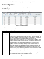
Port Configuration........................................................................................................................................................................ 14
Port Settings..................................................................................................................................................................................................14
Port Description ............................................................................................................................................................................................15
Port Error Disabled .......................................................................................................................................................................................16
Static ARP Settings...................................................................................................................................................................... 16
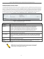
User Accounts .............................................................................................................................................................................. 18
Admin and User Privileges ......................................................................................................................................................................18
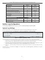
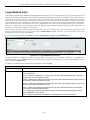
System Log Configuration ........................................................................................................................................................... 19
System Log Settings......................................................................................................................................................................................19
System Log Host...........................................................................................................................................................................................20
System Severity Settings.............................................................................................................................................................. 20
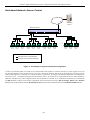
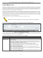
DHCP/BOOTP Relay................................................................................................................................................................... 21
DHCP/BOOTP Relay Global Settings ..........................................................................................................................................................21
DHCP/BOOTP Relay Interface Settings.......................................................................................................................................................24
DHCP Local Relay Settings......................................................................................................................................................... 24
DHCP Auto Configuration Settings ............................................................................................................................................. 25
MAC Address Aging Time .......................................................................................................................................................... 26
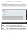
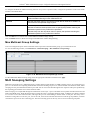
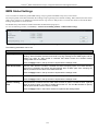
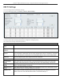
Web Settings ................................................................................................................................................................................ 26
iii
xStack® DGS-3200 Series Layer 2 Gigabit Ethernet Managed Switch
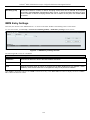
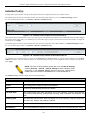
Telnet Settings.............................................................................................................................................................................. 27
Password Encryption.................................................................................................................................................................... 27
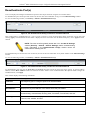
CLI Paging Settings ..................................................................................................................................................................... 28
Firmware Information .................................................................................................................................................................. 28
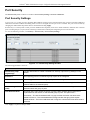
Power Saving Settings.................................................................................................................................................................. 30
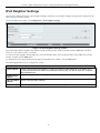
Dual Configuration Settings......................................................................................................................................................... 31
SMTP Settings ............................................................................................................................................................................. 33
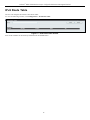
Ping Test ...................................................................................................................................................................................... 34
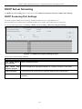
SNTP Settings .............................................................................................................................................................................. 35
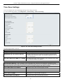
Time Settings ................................................................................................................................................................................................35
Time Zone Settings .......................................................................................................................................................................................36
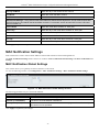
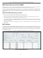
MAC Notification Settings .......................................................................................................................................................... 37
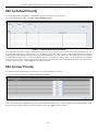
MAC Notification Global Settings................................................................................................................................................................37
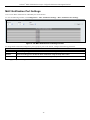
MAC Notification Port Settings....................................................................................................................................................................38
SNMP Settings............................................................................................................................................................................. 39
SNMP Global State Settings .........................................................................................................................................................................40
SNMP Linkchange Trap Settings..................................................................................................................................................................40
SNMP View Table ........................................................................................................................................................................................41
SNMP Group Table ......................................................................................................................................................................................42
SNMP User Table .........................................................................................................................................................................................43
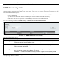
SNMP Community Table..............................................................................................................................................................................44
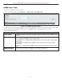
SNMP Host Table .........................................................................................................................................................................................45
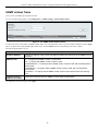
SNMP v6Host Table .....................................................................................................................................................................................46
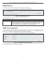
SNMP Engine ID ..........................................................................................................................................................................................47
SNMP Trap Configuration............................................................................................................................................................................47
RMON ..........................................................................................................................................................................................................48
CPU Filter L3 Control Packet Settings ........................................................................................................................................ 48
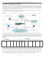
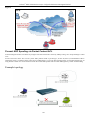
Single IP Management ................................................................................................................................................................. 48
Single IP Settings..........................................................................................................................................................................................50
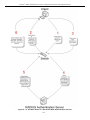
Topology.......................................................................................................................................................................................................52
Firmware Upgrade ........................................................................................................................................................................................58
Configuration File Backup/Restore...............................................................................................................................................................58
Upload Log File ............................................................................................................................................................................................58
SD Card FS Settings..................................................................................................................................................................... 59
L2 Features .....................................................................................................................................................61
Jumbo Frame................................................................................................................................................................................ 61
Egress Filter Settings.................................................................................................................................................................... 62
802.1Q VLAN.............................................................................................................................................................................. 62
Private VLAN Settings ................................................................................................................................................................ 71
802.1v Protocol VLAN ................................................................................................................................................................ 76
802.1v Protocol Group Settings ....................................................................................................................................................................76
802.1v Protocol VLAN Settings ...................................................................................................................................................................77
MAC-based VLAN Settings ........................................................................................................................................................ 78
GVRP Settings ............................................................................................................................................................................. 78
iv
xStack® DGS-3200 Series Layer 2 Gigabit Ethernet Managed Switch
PVID Auto Assign Settings ......................................................................................................................................................... 79
Port Trunking ............................................................................................................................................................................... 80
VLAN Trunk Settings .................................................................................................................................................................. 83
LACP Port Settings...................................................................................................................................................................... 84
Traffic Segmentation.................................................................................................................................................................... 85
IGMP Snooping ........................................................................................................................................................................... 85
IGMP Snooping Settings ..............................................................................................................................................................................85
Data Driven Learning Settings......................................................................................................................................................................89
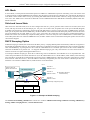
ISM VLAN Settings......................................................................................................................................................................................90
Restrictions and Provisos.........................................................................................................................................................................90
ISM Profile Settings......................................................................................................................................................................................93
IP Multicast Profile Settings .........................................................................................................................................................................94
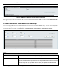
Limited Multicast Address Range Settings ...................................................................................................................................................95
Max Multicast Group Settings ......................................................................................................................................................................96
MLD Snooping Settings............................................................................................................................................................... 96
Port Mirroring ............................................................................................................................................................................ 100
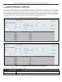
Loopback Detection Settings ..................................................................................................................................................... 101
Spanning Tree ............................................................................................................................................................................ 102
STP Bridge Global Settings ........................................................................................................................................................................105
STP Port Settings ........................................................................................................................................................................................107
MST Configuration Identification...............................................................................................................................................................108
STP Instance Settings..................................................................................................................................................................................109
MSTP Port Information ..............................................................................................................................................................................110
Forwarding & Filtering .............................................................................................................................................................. 111
Unicast Forwarding.....................................................................................................................................................................................111
Multicast Forwarding ..................................................................................................................................................................................111
Multicast Filtering Mode.............................................................................................................................................................................112
QoS ................................................................................................................................................................113
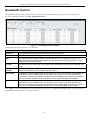
Bandwidth Control..................................................................................................................................................................... 115
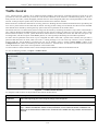
Traffic Control ........................................................................................................................................................................... 116
802.1p Default Priority............................................................................................................................................................... 118
802.1p User Priority ................................................................................................................................................................... 118
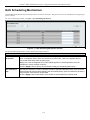
QoS Scheduling Mechanism ...................................................................................................................................................... 119
Security .........................................................................................................................................................120
Safeguard Engine ....................................................................................................................................................................... 120
Trusted Host............................................................................................................................................................................... 122
IP-MAC-Port Binding (IMPB)................................................................................................................................................... 123
IMPB Global Settings .................................................................................................................................................................................125
IMPB Port Settings .....................................................................................................................................................................................126
IMPB Entry Settings ...................................................................................................................................................................................128
DHCP Snooping Entries .............................................................................................................................................................................129
MAC Block List..........................................................................................................................................................................................130
Port Security............................................................................................................................................................................... 131
Port Security Settings..................................................................................................................................................................................131
v
xStack® DGS-3200 Series Layer 2 Gigabit Ethernet Managed Switch
Port Lock Entries ........................................................................................................................................................................................132
DHCP Server Screening............................................................................................................................................................. 133
DHCP Screening Port Settings....................................................................................................................................................................133
DHCP Offer Filtering..................................................................................................................................................................................134
Guest VLAN .............................................................................................................................................................................. 135
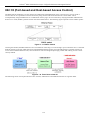
802.1X (Port-based and Host-based Access Control) ................................................................................................................ 136
Authentication Server ............................................................................................................................................................................137
Authenticator .........................................................................................................................................................................................137
Client .....................................................................................................................................................................................................138
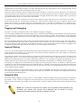
Authentication Process ..........................................................................................................................................................................138
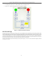
Understanding 802.1X Port-based and Host-based Network Access Control........................................................................................139
802.1X Settings...........................................................................................................................................................................................141
802.1X User ................................................................................................................................................................................................142
Initialize Port(s) ..........................................................................................................................................................................................143
Reauthenticate Port(s) .................................................................................................................................................................................144
Authentic RADIUS Server..........................................................................................................................................................................145
SSL Settings............................................................................................................................................................................... 146
SSH ............................................................................................................................................................................................ 148
SSH Configuration......................................................................................................................................................................................149
SSH Authmode and Algorithm Settings .....................................................................................................................................................150
SSH User Authentication Mode..................................................................................................................................................................152
Access Authentication Control................................................................................................................................................... 153
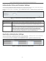
Authentication Policy and Parameter Settings ............................................................................................................................................154
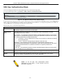
Application Authentication Settings ...........................................................................................................................................................154
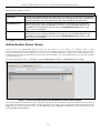
Authentication Server Group ......................................................................................................................................................................155
Authentication Server Host .........................................................................................................................................................................157
Login Method Lists.....................................................................................................................................................................................158
Enable Method Lists ...................................................................................................................................................................................159
Configure Local Enable Password ..............................................................................................................................................................160
Enable Admin .............................................................................................................................................................................................160
MAC-based Access Control (MAC) .......................................................................................................................................... 161
MAC Settings .............................................................................................................................................................................................161
MAC Local Settings....................................................................................................................................................................................164
Web-based Access Control (WAC) ........................................................................................................................................... 164
WAC Global Settings..................................................................................................................................................................................166
WAC User Settings.....................................................................................................................................................................................167
WAC Port Settings......................................................................................................................................................................................169
Japanese Web-based Access Control (JWAC)........................................................................................................................... 170
JWAC Global Settings ................................................................................................................................................................................170
JWAC Port Settings ....................................................................................................................................................................................172
JWAC User Settings ...................................................................................................................................................................................173
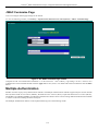
JWAC Customize Page Language ..............................................................................................................................................................173
JWAC Customize Page...............................................................................................................................................................................174
Multiple Authentication ............................................................................................................................................................. 174
Authorization Network State Settings.........................................................................................................................................................177
vi
xStack® DGS-3200 Series Layer 2 Gigabit Ethernet Managed Switch
Multiple Authentication Settings ................................................................................................................................................................177
Guest VLAN ...............................................................................................................................................................................................178
IGMP Access Control Settings (IGMP Authentication) ............................................................................................................ 179
ARP Spoofing Prevention Settings ............................................................................................................................................ 180
ACL ...............................................................................................................................................................181
ACL Configuration Wizard........................................................................................................................................................ 181
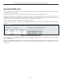
Access Profile List ..................................................................................................................................................................... 182
CPU Access Profile List............................................................................................................................................................. 198
Time Range Settings .................................................................................................................................................................. 210
Monitoring ....................................................................................................................................................212
Device Environment................................................................................................................................................................... 212
Cable Diagnostics ...................................................................................................................................................................... 213
CPU Utilization.......................................................................................................................................................................... 214
Port Utilization........................................................................................................................................................................... 215
Packet Size ................................................................................................................................................................................. 216
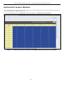
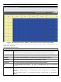
Packets ....................................................................................................................................................................................... 218
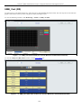
Received (RX) ............................................................................................................................................................................................218
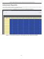
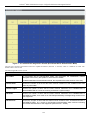
UMB_Cast (RX) .........................................................................................................................................................................................220
Transmitted (TX) ........................................................................................................................................................................................221
Errors.......................................................................................................................................................................................... 223
Received (RX) ............................................................................................................................................................................................223
Transmitted (TX) ........................................................................................................................................................................................225
Port Access Control.................................................................................................................................................................... 227
RADIUS Authentication .............................................................................................................................................................................227
RADIUS Account Client.............................................................................................................................................................................228
Authenticator State......................................................................................................................................................................................230
Authenticator Statistics ...............................................................................................................................................................................232
Authenticator Session Statistics ..................................................................................................................................................................235
Authenticator Diagnostics...........................................................................................................................................................................238
Browse ARP Table..................................................................................................................................................................... 241
Browse VLAN ........................................................................................................................................................................... 241
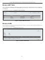
Browse Router Port .................................................................................................................................................................... 242
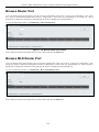
Browse MLD Router Port .......................................................................................................................................................... 242
Browse Session Table ................................................................................................................................................................ 243
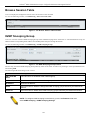
IGMP Snooping Group .............................................................................................................................................................. 243
MLD Snooping Group ............................................................................................................................................................... 244
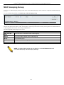
WAC Authenticating State......................................................................................................................................................... 245
JWAC Host Table ...................................................................................................................................................................... 246
MAC Address Table .................................................................................................................................................................. 247
System Log ................................................................................................................................................................................ 248
MAC Authentication State ......................................................................................................................................................... 249
Save and Tools..............................................................................................................................................250
Save Configuration..................................................................................................................................................................... 251
vii
xStack® DGS-3200 Series Layer 2 Gigabit Ethernet Managed Switch
Save Log .................................................................................................................................................................................... 251
Save All...................................................................................................................................................................................... 252
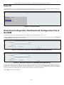
Download Configuration File/Download Configuration File to NV-RAM ............................................................................... 252
Download Configuration File to SD Card.................................................................................................................................. 253
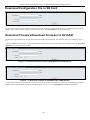
Download Firmware/Download Firmware to NV-RAM ........................................................................................................... 253
Download Firmware to SD Card................................................................................................................................................ 254
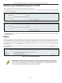
Upload Configuration File/Upload Configuration File to TFTP................................................................................................ 254
Upload Log File/Upload Log File to TFTP................................................................................................................................ 255
Reset........................................................................................................................................................................................... 255
Reboot System ........................................................................................................................................................................... 256
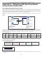
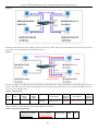
Appendix A – Mitigating ARP Spoofing Attacks Using Packet Content ACL ......................................257
Appendix B – Switch Log Entries...............................................................................................................264
Appendix C – Trap Logs .............................................................................................................................276
Appendix D – Password Recovery Procedure...........................................................................................279
Appendix E – Glossary ................................................................................................................................280
Warranty ......................................................................................................................................................282
viii
xStack® DGS-3200 Series Layer 2 Gigabit Ethernet Managed Switch
Intended Readers
The DGS-3200 Series Manual contains i nformation for set up an d m anagement of t he Switch. This m anual i s i ntended for
network managers familiar with network management concepts and terminology.
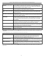
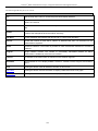
Typographical Conventions
Convention
Description
[]
In a command line, square brackets indicate an optional entry. For example: [copy
filename] means that optionally you can type copy followed by the name of the file. Do
not type the brackets.
Bold font
Indicates a button, a toolbar icon, menu, or menu item. For example: Open the File
menu and choose Cancel. Used for emphasis. May also indicate system messages or
prompts appearing on screen. For example: You have mail. Bold font is also used to
represent filenames, program names and commands. For example: use the copy
command.
Boldface
Font
Typewriter
Indicates commands and responses to prompts that must be typed exactly as printed in
the manual.
Initial capital letter
Indicates a window name. Names of keys on the keyboard have initial capitals. For
example: Click Enter.
Italics
Indicates a window name or a field. Also can indicate a variables or parameter that is
replaced with an appropriate word or string. For example: type filename means that the
actual filename should be typed instead of the word shown in italic.
Menu Name > Menu
Option
Menu Name > Menu Option Indicates the menu structure. Device > Port > Port
Properties means the Port Properties menu option under the Port menu option that is
located under the Device menu.
ix
xStack® DGS-3200 Series Layer 2 Gigabit Ethernet Managed Switch
Notes, Notices, and Cautions
A NOTE indicates important information that helps make better use of the
device.
A NOTICE indicates either potential damage to hardware or loss of data
and tells how to avoid the problem.
A CAUTION indicates a potential for property damage, personal injury, or
death.
Safety Cautions
Use the following safety guidelines to ensure your own personal safety and to help protect your system from potential damage.
Throughout this safety section, the caution icon (
followed.
) is used to indicate ca utions and precautions that need to be reviewed and
To reduce the risk of bodily injury, electrical shock, fire, and damage to the equipment observe the following precautions.
Observe and follow service markings.
Do not service any product except as explained in the system documentation.
Opening or removing covers that are marked with the triangular symbol with a l ightning bolt may expose the user to
electrical shock.
Only a trained service technician should service components inside these compartments.
If any of the following conditions occur, unplug the product from the electrical outlet a nd replace the part or contact your
trained service provider:
Damage to the power cable, extension cable, or plug.
An object has fallen into the product.
The product has been exposed to water.
The product has been dropped or damaged.
The product does not operate correctly when the operating instructions are correctly followed.
Keep your system away from radiators and heat sources. Also, do not block cooling vents.
Do not spill food or liquids on system components, and never operate the product i n a wet environment. If the system gets
wet, see the appropriate section in the troubleshooting guide or contact your trained service provider.
x
xStack® DGS-3200 Series Layer 2 Gigabit Ethernet Managed Switch
Do not push any objects into the openings of the system. Doing so can cause fire or el ectric shock by shorting out interior
components.
Use the product only with approved equipment.
Allow the product to cool before removing covers or touching internal components.
Operate the product only from the type of external power source indicated on the electrical ratings label. If unsure of the type
of power source required, consult your service provider or local power company.
To help avoid damaging the system, be sure the voltage selection switch (if provided) on the power supply is set to match the
power available at the Switch’s location:
115 volts (V)/60 hertz (Hz) in most of North and South America and some Far Eastern countries such as South Korea
and Taiwan
100 V/50 Hz in eastern Japan and 100 V/60 Hz in western Japan
230 V/50 Hz in most of Europe, the Middle East, and the Far East
Also, be sure that attached devices are electrically rated to operate with the power available in your location.
Use only a pproved power c able(s). If y ou ha ve n ot been provided wi th a p ower c able f or y our s ystem or f or a ny AC powered option intended for your system, purchase a power cable that is approved for use in your country. The power cable
must be rated for the product and for the voltage and current marked on the product's electrical ratings label. The voltage and
current rating of the cable should be greater than the ratings marked on the product.
To help prevent electric shock, plug the system and peripheral power cables into properly grounded electrical outlets. These
cables are e quipped wi th t hree-prong pl ugs t o hel p e nsure p roper grounding. D o n ot use ada pter plugs or remove t he
grounding prong from a cable. If using an extension cable is necessary, use a 3-wire cable with properly grounded plugs.
Observe ex tension cab le an d pow er str ip ratings. Mak e su re th at th e total a mpere rating of all pro ducts plugged i nto th e
extension cable or power strip does not exceed 80 percent of the ampere ratings limit for the extension cable or power strip.
To help protect the system from sudden, transient increases and decreases in elect rical power, use a surge suppressor, line
conditioner, or uninterruptible power supply (UPS).
Position system cables and power cables carefully; route cables so that they cannot be stepped on or tripped over. Be sure
that nothing rests on any cables.
Do not modify power cables or plugs. Consult a licensed electrician or your power company for site modifications. Always
follow your local/national wiring rules.
When conn ecting or disconnecting power to hot-pluggable power su pplies, if of fered with y our system, o bserve t he
following guidelines:
Install the power supply before connecting the power cable to the power supply.
Unplug the power cable before removing the power supply.
If the system has multiple sources of power, disconnect power from the system by unplugging all power cables from
the power supplies.
Move products with care; ens ure that a ll casters and/or stabilizers are fi rmly connected to the system. Avoid sudden stops
and uneven surfaces.
General Precautions for Rack-Mountable Products
Observe the following precautions for rack stability and safety. Also, refer to th e rack installation documentation accompanying
the system and the rack for specific caution statements and procedures.
Systems are considered to be components in a rack. Thus, "component" refers to any system as well as to various peripherals
or supporting hardware.
xi
xStack® DGS-3200 Series Layer 2 Gigabit Ethernet Managed Switch
CAUTION: Installing systems in a rack without the front and side stabilizers installed could
cause the rack to tip over, potentially resulting in bodily injury under certain circumstances.
Therefore, always install the stabilizers before installing components in the rack. After
installing system/components in a rack, never pull more than one component out of the
rack on its slide assemblies at one time. The weight of more than one extended
component could cause the rack to tip over and may result in serious injury.
Before working on the rack, make sure t hat the sta bilizers are secured to the rack, extended to the floor, and that t he full
weight of the rack rests on the fl oor. Install front and sid e stabilizers on a sing le rack or front stabilizers for joined multiple
racks before working on the rack.
Always load the rack from the bottom up, and load the heaviest item in the rack first.
Make sure that the rack is level and stable before extending a component from the rack.
Use caution when pressing the co mponent rail release latch es and sliding a co mponent into or ou t of a rack; the slide rails
can pinch your fingers.
After a component is inserted into the rack, carefully extend the rail into a l ocking position, and then slide the component
into the rack.
Do not ove rload t he AC supply bra nch ci rcuit th at prov ides power to th e rack. The t otal rack lo ad should not ex ceed 80
percent of the branch circuit rating.
Ensure that proper airflow is provided to components in the rack.
Do not step on or stand on any component when servicing other components in a rack.
NOTE: A qualified electrician must perform all connections to DC power and to safety
grounds. All electrical wiring must comply with applicable local or national codes and
practices.
CAUTION: Never defeat the ground conductor or operate the equipment in the absence
of a suitably installed ground conductor. Contact the appropriate electrical inspection
authority or an electrician if uncertain that suitable grounding is available.
CAUTION: The system chassis must be positively grounded to the rack cabinet frame.
Do not attempt to connect power to the system until grounding cables are connected.
Completed power and safety ground wiring must be inspected by a qualified electrical
inspector. An energy hazard will exist if the safety ground cable is omitted or
disconnected.
CAUTION: When mounting the Switch on a cement wall, a proper concrete sleeve
anchor should be used, such as the one that is included in the optional D-Link Wall Mount
kit (DRE-KIT018).
xii
xStack® DGS-3200 Series Layer 2 Gigabit Ethernet Managed Switch
Lithium Battery Precaution
CAUTION: Incorrectly replacing the lithium battery of the Switch may cause the battery to
explode. Replace this battery only with the same or equivalent type recommended by the
manufacturer. Discard used batteries according to the manufacturer’s instructions.
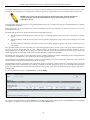
Protecting Against Electrostatic Discharge
Static electricity can harm delicate components inside the system. To prevent static damage, discharge static electricity from your
body before touching any of the electronic components, such as the microprocessor. This can be done by periodically touching an
unpainted metal surface on the chassis.
The following steps can also be taken prevent damage from electrostatic discharge (ESD):
1.
When unpacking a static-sensitive component from its shipping carton, do not remove the component from the antistatic
packing material until ready to install the com ponent in the system. Just be fore unwrapping the a ntistatic packaging, be
sure to discharge static electricity from your body.
2.
When transporting a sensitive component, first place it in an antistatic container or packaging.
3.
Handle all sensitive components in a static-safe area. If possible, use antistatic floor pads, workbench pads and an
antistatic grounding strap.
xiii
xStack® DGS-3200 Series Layer 2 Gigabit Ethernet Managed Switch
Section 1
Web-based Switch Configuration
Introduction
Logging onto the Web Manager
Web-Based User Interface
Introduction
All software functions of the Switch can be managed, configured, and monitored via the embedded web-based (HTML) interface.
Manage the Switch from remote stations anywhere on the network through a standard browser, such as Internet Explorer 5.5 or
later, Net scape 8. 0 or l ater, Fi refox 2.0 or l ater, o r Apple Sa fari 3.0. The b rowser act s as a u niversal a ccess t ool a nd ca n
communicate directly with the Switch using the HTTP protocol.
The Web-based m anagement m odule a nd the Console program (and T elnet) a re different ways t o access t he sa me interna l
switching software and configure it. Th us, all settings encountered in web-based management are t he same as t hose found in the
console program.
Logging onto the Web Manager
To begin managing the Switch, simply run the browser installed on your computer and point it to the IP address you have defined
for the device. The URL in the address bar should read something like: http://123.123.123.123, where the numbers 123 represent
the IP address of the Switch.
NOTE: The factory default IP address is 10.90.90.90.
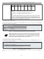
This opens the management module's user authentication window, as seen below.
Figure 1- 1. Enter Network Password window
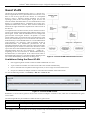
Enter “admin” in both the User Name field and t he Password field and click OK. This will ope n the Web-based user interface.
The Switch management features available in the web-based manager are explained below.
1
xStack® DGS-3200 Series Layer 2 Gigabit Ethernet Managed Switch
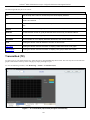
Web-based User Interface
The user i nterface provides access to various Switch configuration and management windows, allows the user to
performance statistics, and permits graphical monitoring of the system status.
view
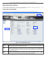
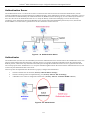
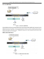
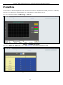
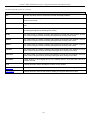
Areas of the User Interface
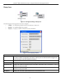
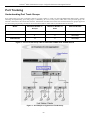
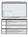
The figure below shows the user interface. Three distinct areas divide the user interface, as described in the table.
Figure 1- 2. Main Web-Manager window
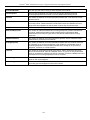
Area
Function
Area 1
Select the folder or window to display. Open folders and click the hyperlinked window buttons and
subfolders contained within them to display windows.
Area 2
Presents a graphical near real-time image of the front panel of the Switch. This area displays the
Switch's ports and expansion modules and shows port activity, depending on the specified mode.
Some management functions, including port monitoring are accessible here. Click the D-Link logo to
go to the D-Link website.
Area 3
Presents Switch status based on user selection and the entry of configuration data. In addition,
hyperlinks are offered for many Switch features to enable quick configuration.
2
xStack® DGS-3200 Series Layer 2 Gigabit Ethernet Managed Switch
Web Pages
When connecting to the management mode of the Switch with a Web browser, a login screen is displayed. Enter a user name and
password to access the Switch's management mode.
Below is a list of the folders and windows available in the Web interface:
Configuration – C ontains the following main folders, windows, and related windows: System Information, Serial Port Settings,
IP Address, IPv6 Interface Settings, IPv6 Route Table, IPv6 Neighbor Settings, Port Configuration, Port Settings, Port Description,
Port Error Disabled, Static ARP Setting s, User Accounts, Syst em Lo g Con figuration, System Lo g Settings, System Lo g Ho st,
System Severity Settings, DHCP/BOOTP Relay, DHCP/BOOTP Relay Global Settin gs, DHCP/BOOTP Relay Interface Settings,
DHCP L ocal Relay Set tings, DHC P A uto Configuration Settings, M AC Ad dress A ging Ti me, W eb Set tings, Tel net Set tings,
Password En cryption, CLI Pag ing Setting s, Firmware Information, Power Sav ing Settin gs, Dual Configu ration Settin gs, SMTP
Settings, Pi ng Test, SNTP Settings, Tim e Settin gs, Tim e Zo ne Setting s, M AC Notification Settin gs, MAC No tification Gl obal
Settings, MAC Notification Port Settings, SNMP Settings, SNMP Global State Settings, SNMP Linkchange Trap Settings, SNMP
View Table, SNMP Group Table, SNMP User Table, SNMP Community Table, SNMP Host Table, SNMP v6Host Table, SNMP
Engine ID, SNMP Trap C onfiguration, R MON, CPU Filter L3 Con trol Pack et Se ttings, Single IP Man agement, an d Single IP
Settings, Topology, Firmware Upgrade, Configuration File Backup/Restore, Upload Log File, and SD Card FS Settings.
L2 Features – Contains the following main folders, windows, and related windows: Jumbo Frame, Egress Filter Settings, 802.1Q
VLAN, Priv ate VLAN Settin gs, 802.1v Protocol VLAN, 802 .1v Pro tocol Gro up Settings, 802 .1v Protocol VLAN Setting s,
MAC-based VLAN Settin gs, GVR P Setting s, PVID Au to Assign Settings, Po rt Tru nking, VLAN Trunk Setting s, LACP Po rt
Settings, Traffic Segmentation, IGMP Snooping, IGMP Snooping Settings, Data Driven Learning Settings, ISM VLAN Settings,
ISM Pro file Settin gs, IP Multicast Pro file Settings, Lim ited M ulticast Add ress Range Settin gs, Max M ulticast Gro up Settin gs,
MLD Snooping Settings, P ort M irroring, L oopback Detection Settings, Spanning T ree, ST P B ridge Global Set tings, S TP Port
Settings, MST Co nfiguration Id entification, STP In stance Setti ngs, MSTP Port In formation, Forward ing & Filterin g, Unicast
Forwarding, Multicast Forwarding, and Multicast Filtering Mode.
QoS – Contains the following main folders, windows, and related windows: Bandwidth Control, Traffic Control, 802.1p Default
Priority, 802.1p User Priority, and QoS Scheduling Mechanism.
Security – Contains the following main folders, windows, and related windows: Safeguard Engine, Trusted Host, IP-MAC-Port
Binding (IMPB), IMPB Global Settings, IMPB Port Settings, IMPB Entry Settings, DHCP Snooping Entries, MAC Blocked List,
Port Security, Port Security Settings, Port Lo ck Entries, DHCP Server Screening, DHCP Screening Port Settings , DHCP Offer
Filtering, 802 .1X, 802.1X Settings, 802 .1X User, Au thentic RADIUS Serv er, Gu est VLAN, SSL Settin gs, SSH, SSH
Configuration, SSH Authmode an d Al gorithm Settin gs, SSH Us er Authentication Mode, Acce ss Au thentication Con trol,
Authentication Policy and Parameter Settings, Application Authentication Settings, Authentication Server Group, Authentication
Server Host, Login Method Lists, Enable Method Lists, Configure Local Enable Password, Enable Admin, MAC-based Access
Control (M AC), MAC Settings, M AC Lo cal Settin gs, Web-based Access Con trol (WAC), WAC Gl obal Setting s, WAC User
Settings, WAC Port Settings, Japanese Web-based Access Control (JWAC), JWAC Global Settings, JWAC Port Settings, JWAC
User Settings, JWAC Customize Page Language, JWAC C ustomize Page, Multiple Authentication, Authorization Network State
Settings, Multiple Authentication Settings, Guest VLAN, IGMP Access Control Settings, and ARP Spoofing Prevention Settings.
ACL – Contains the following m ain folders, windows, and related windows: Access Configuration Wizard, Access Profile List,
CPU Access Profile List, and Time Range Settings.
Monitoring – Contains the following main folders, windows, and related windows: Device Environment, Cable Diagnostics, CPU
Utilization, Port Utilization, Packet Size, Packets, Recei ved (RX), UM B_cast (R X), Transmitted (TX), Errors, Received (R X),
Transmitted (TX), Port Access Con trol, RADIUS Authentication, RA DIUS Acc ount Client, Authenticator State, Authenticator
Statistics, Authenticator Session Statistics, Au thenticator Diagnostics, Browse ARP Table, Browse VLAN, Browse Router Port,
Browse MLD Router Port, Browse Session Table, IGMP Snooping Group, MLD Snooping Group, WAC Authenticating State,
JWAC Host Table, MAC Address Table, System Log, and MAC Authentication State.
Save – Contains links for Save Configuration, Save Log, and Save All.
Tools – Contains the following windows: Download Configuration File to NV-RAM, Download Configuration File to SD Card,
Download Fir mware to NV- RAM, D ownload Firm ware to SD Ca rd, Up load Con figuration File to TFTP, Upload Lo g File to
TFTP, Reset, and Reboot System.
3
xStack® DGS-3200 Series Layer 2 Gigabit Ethernet Managed Switch
NOTE: Be sure to configure the user name and password in the User
Accounts window before connecting the Switch to the greater network.
4
xStack® DGS-3200 Series Layer 2 Gigabit Ethernet Managed Switch
Section 2
Configuration
Device Information
System Information
Serial Port Settings
IP Address
IPv6 Interface Settings
IPv6 Route Table
IPv6 Neighbor Settings
Port Configuration
Static ARP Settings
User Accounts
System Log Configuration
System Severity Settings
DHCP/BOOTP Relay
DHCP Local Relay Settings
DHCP Auto Configuration Settings
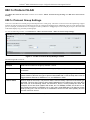
MAC Address Aging Time
Web Settings
Telnet Settings
Password Encryption
CLI Paging Settings
Firmware Information
Power Saving Settings
Dual Configuration Settings
SMTP Settings
Ping Test
SNTP Settings
MAC Notification Settings
SNMP Settings
CPU Filter L3 Control Packet Settings
Single IP Management
SD Card FS Settings (DGS-3200-24 only)
5
xStack® DGS-3200 Series Layer 2 Gigabit Ethernet Managed Switch
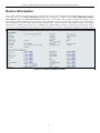
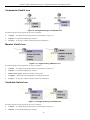
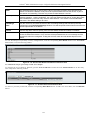
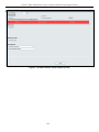
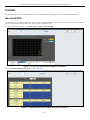
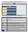
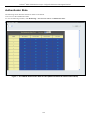
Device Information
This window contains the main settings for all major functions for the Switch. It appears automatically when you log on to the
Switch. To retu rn to the Device I nformation w indow af ter v iewing oth er windows, click th e DGS-3200-10/DGS-3200-16/
DGS-3200-24 folder. Th e Device In formation w indow show s th e Switch’s MAC Ad dress (assigned by t he fact ory an d
unchangeable), the Boot PROM Version, Firmware Version, Hardware Version, and many other important types of information.
This is h elpful to k eep track o f PR OM and firm ware upd ates and to obtain th e Switch ’s M AC add ress for en try in to ano ther
network device’s address table, if necessary. In addition, this window displays the status of functions on the Switch to quickly
assess their current global status. Many functions are hyper-linked for easy access to enable quick configuration from this window.
Figure 2- 1. Device Information window
6
xStack® DGS-3200 Series Layer 2 Gigabit Ethernet Managed Switch
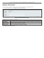
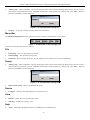
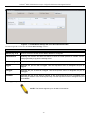
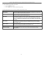
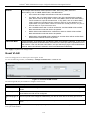
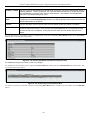
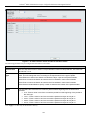
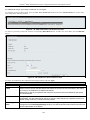
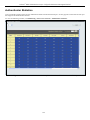
System Information
The user can enter a System Name, System Location, and System Contact to aid in defining the Switch.
To view the following window, click Configuration > System Information:
Figure 2- 2. System Information window
The fields that can be configured are described below:
Parameter
Description
System Name
Enter a system name for the Switch, if desired. This name will identify it in the Switch network.
System Location
Enter the location of the Switch, if so desired.
System Contact
Enter a contact name for the Switch, if so desired.
Click Apply to implement changes made.
7
xStack® DGS-3200 Series Layer 2 Gigabit Ethernet Managed Switch
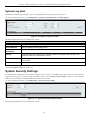
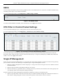
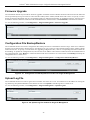
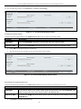
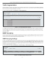
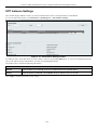
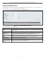
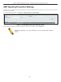
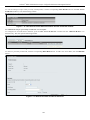
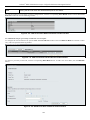
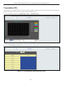
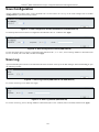
Serial Port Settings
The user can adjust the Baud Rate and the Auto Logout values.
To view the following window, click Configuration > Serial Port Settings:
Figure 2- 3. Serial Port Settings window
Baud Rate
This field specifies the baud rate for the serial port on the Switch. There are four possible
baud rates to choose from, 9600, 19200, 38400 and 115200. For a connection to the Switch
using the CLI interface, the baud rate must be set to 115200, which is the default setting.
Auto Logout
Select the logout time used for the console interface. This automatically logs the user out after
an idle period of time, as defined. Choose from the following options: 2 mins, 5 mins, 10 mins,
15 mins or Never. The default setting is 10 mins.
Click Apply to implement changes made.
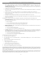
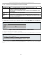
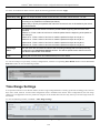
IP Address
The IP ad dress m ay in itially b e set using th e con sole in terface prior t o conn ecting to it th rough th e Eth ernet. If th e Switch I P
address ha s not y et bee n c hanged, rea d t he i ntroduction of t he DGS-3200 Series CLI Manual for m ore in formation. The Web
manager will display the Switch’s current IP settings.
To view the following window, click Configuration > IP Address:
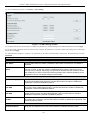
Figure 2- 4. IP Address window
To manually assign the Switch’s IP address, subnet mask, and default gateway address:
1.
Click the Manual radio button at the top of the window.
2.
Enter the appropriate IP Address and Subnet Mask.
3.
If accessing the Switch from a different subnet from the one it is installed on, enter the IP address of the default Gateway.
If managing the Switch fro m the subnet on which it is i nstalled, the user may leave t he default address (0.0.0.0) in this
field.
4.
If the Switch has no previously configured VLANs, th e user can u se the Management VLAN Nam e entitled “default”.
This default Management VLAN contains all of t he Switch ports as m embers. If t he Switch has previously configured
VLANs, the user will need t o en ter t he VLAN ID of the VLAN th at contains th e port con nected to th e m anagement
station that will access the Switch. The Switch will allow m anagement access from stations with t he same VID listed
here.
8
xStack® DGS-3200 Series Layer 2 Gigabit Ethernet Managed Switch
NOTE: The Switch’s factory default IP address is 10.90.90.90 with a
subnet mask of 255.0.0.0 and a default gateway of 0.0.0.0.
To use the DHCP or BOOTP protocols to assign the Switch an IP address, subnet mask, and default gateway address:
Use the radio button at the top of the window to choose either DHCP or BOOTP. This selects the method the Switch assigns an IP
address on the next reboot.
The following parameters may be configured or viewed:
Parameter
Description
Manual
Allows the entry of an IP address, subnet mask, and a default gateway for the Switch. These fields
should be of the form xxx.xxx.xxx.xxx, where each xxx is a number (represented in decimal form)
between 0 and 255. This address should be a unique address on the network assigned for use by
the network administrator.
DHCP
The Switch will send out a DHCP broadcast request when it is powered up. The DHCP protocol
allows IP addresses, network masks, and default gateways to be assigned by a DHCP server. If
this option is set, the Switch will first look for a DHCP server to provide it with this information
before using the default or previously entered settings.
BOOTP
The Switch will send out a BOOTP broadcast request when it is powered up. The BOOTP protocol
allows IP addresses, network masks, and default gateways to be assigned by a central BOOTP
server. If this option is set, the Switch will first look for a BOOTP server to provide it with this
information before using the default or previously entered settings.
Subnet Mask
A Bitmask that determines the extent of the subnet that the Switch is on. Should be of the form
xxx.xxx.xxx.xxx, where each xxx is a number (represented in decimal) between 0 and 255. The
value should be 255.0.0.0 for a Class A network, 255.255.0.0 for a Class B network, and
255.255.255.0 for a Class C network, but custom subnet masks are allowed.
Gateway
IP address that determines where packets with a destination address outside the current subnet
should be sent. This is usually the address of a router or a host acting as an IP gateway. If your
network is not part of an intranet, or you do not want the Switch to be accessible outside your local
network, you can leave this field unchanged.
Management
VLAN Name
This allows the entry of a VLAN name from which a management station will be allowed to manage
the Switch using TCP/IP (in-band via Web manager or Telnet). Management stations that are on
VLANs other than the one entered here will not be able to manage the Switch in-band unless their
IP addresses are entered in the Trusted Host window (Security > Trusted Host). If VLANs have
not yet been configured for the Switch, the default VLAN contains all of the Switch’s ports. There
are no entries in the Trusted Host table, by default, so any management station that can connect to
the Switch can access the Switch until a management VLAN is specified or Management Station IP
addresses are assigned.
Click Apply to implement changes made.
9
xStack® DGS-3200 Series Layer 2 Gigabit Ethernet Managed Switch
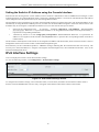
Setting the Switch’s IP Address using the Console Interface
Each Switch must be assi gned its own IP Address, which is used for communication with an SNMP network manager or other
TCP/IP application (for example BOOTP, TFTP). The Switch’s default IP a ddress is 10.90.90.90. The default Switch IP address
can be changed to meet the specification of your networking address scheme.
The IP address for the Switch must be set before the Web-based manager can manage the switch. The Switch IP address can be
automatically set using BOOTP or DHCP protocols, in which case the actual address assigned to the Switch must be known. The
IP address may be set using the Command Line Interface (CLI) over the console serial port as follows:
Starting at the command line prom
pt, enter the c ommands config ipif Sy stem ipaddress xxx.xxx.xxx.xxx/
yyy.yyy.yyy.yyy. Where the x’s represent the IP address t o be assigned to the IP interface nam ed System and the y’s
represent the corresponding subnet mask.
Alternatively, the user ca n enter config i pif Sy stem ipa ddress xxx.xxx.xxx.xxx/z. Whe re the x’s represent the IP
address to be assigned to the IP interface named System and the z represents the corresponding number of subnets in
CIDR notation.
The IP interface named System on the Switch can be assigned an IP address and subnet mask, which can then be used to connect a
management station to the Switch’s Telnet or Web-based management agent.
Successful entry of t he command will produce a “Success” message, indicating that the command execution was correctly. The
user may now utilize this address to c onfigure or m anage the Switch through Tel net, the Command Line Interface (CLI) or the
Web-based management (GUI).
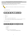
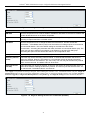
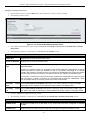
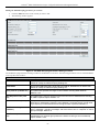
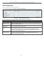
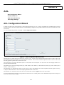
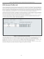
IPv6 Interface Settings
Users can display the Switch’s current IPv6 interface settings.
To view the following window, click Configuration > IPv6 Interface Settings:
Figure 2- 5. IPv6 Interface Settings window
To configure IPv6 interface settings, enter an Interface Name, a VLAN Name, and make sure the Interface Admin. State is
Enabled. Click the Create button. The new entry will appear in the Interface Table at the bottom of the window.
10
xStack® DGS-3200 Series Layer 2 Gigabit Ethernet Managed Switch
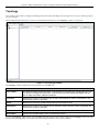
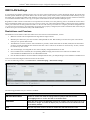
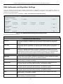
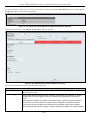
To modify an IPv6 Interface Table entry, click the corresponding Edit button. The following window opens:
Figure 2- 6. IPv6 Interface Settings (Edit) window
The IPv6 window i s divided i nto t hree distinct pa rts. The f ollowing parameters may b e co nfigured or viewed at the t op of t he
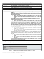
window:
Parameter
Description
Interface Name
The name of the IPv6 interface being modified.
VLAN Name
Enter the VLAN name of the IPv6 interface.
IPv6 Address
Enter the IPv6 address of the interface to be modified.
Admin. State
Toggle the state between Enabled and Disabled.
Link Status
Displays whether the IPv6 Interface is Up or Down.
Member Ports
Displays the port numbers that are part of the IPv6 Interface.
NS Retransmit
Time (04294967295)
Enter a value between 0 and 4294967295. This is the neighbor solicitation’s retransmit timer in
milliseconds. The default is zero.
After making the desired changes, click the Apply button in the top section of the window.
The following parameter is used to configure the Automatic Link Local Address:
Parameter
Description
Automatic Link
Local Address
Toggle between Enabled and Disabled. Enabling this is helpful when no external source of network
addressing information is available. Click the adjacent Apply button when you have finished
configuring the Automatic Link Local Address.
The following parameter is used to add/remove an IPv6 Default Gateway Address from the Switch:
Parameter
Description
Default
Gateway
Enter the IPv6 address of the default gateway you want to add/remove.
Click the Create button to add the default gateway.
Click the Delete button to delete the default gateway.
11
xStack® DGS-3200 Series Layer 2 Gigabit Ethernet Managed Switch
IPv6 Route Table
The user can configure the Switch’s IPv6 Route Table.
To view the following window, click Configuration > IPv6 Route Table:
Figure 2- 7. IPv6 Route Table window
Enter an IPv6 address in the Gateway field and click the Create button.
12
xStack® DGS-3200 Series Layer 2 Gigabit Ethernet Managed Switch
IPv6 Neighbor Settings
The user can configure the Switch’s IPv6 neighbor settings. The Switch’s cu rrent IPv6 neighbor settings will b e displayed in the
table at the bottom of this window.
To view the following window, click Configuration > IPv6 Neighbor Settings:
Figure 2- 8. IPv6 Neighbor Settings window
Enter the Interface Name, Neighbor IPv6 Address, and the Link Layer MAC Address and then click the Add button. The State
can be set to All, Address, Static, or Dynamic.
To look for an IPv6 Neighbor Settings table entry, enter the Interface Name, select the desired State in the middle section of this
window, and then click the Find button.
To delete all the entries being displayed on the table at the bottom of this window, click the Clear button.
The following parameters may be configured or viewed:
Parameter
Description
Interface Name
Enter the name of the IPv6 neighbor. To search for all the current interfaces on the Switch, go to
the second Interface Name field in the middle part of the window, tick the All check box, and then
click the Find button.
Neighbor IPv6
Address
Enter the neighbor IPv6 address.
Link Layer MAC
Address
Enter the link layer MAC address.
State
Use the drop-down menu to select All, Address, Static, or Dynamic.
13
xStack® DGS-3200 Series Layer 2 Gigabit Ethernet Managed Switch
Port Configuration
The Port Configuration folder contains three windows: Port Settings, Port Description, and Port Error Disabled.
Port Settings
To view the following window, click Configuration > Port Configuration > Port Settings:
Figure 2- 9. Port Settings window
To configure switch ports:
1.
Choose the port or sequential range of ports using the From Port and To Port drop-down menus.
2.
Use the remaining drop-down menus to configure the parameters described below:
The following parameters may be configured or viewed:
Parameter
Description
State
Toggle the State field to either enable or disable a given port or group of ports.
Speed/Duplex
Toggle the Speed/Duplex field to either select the speed and duplex/half-duplex state of the
port. Auto denotes auto-negotiation between 10 and 100 Mbps devices, in full- or half-duplex.
The Auto setting allows the port to automatically determine the fastest settings the device the
port is connected to can handle, and then to use those settings. The other options are 10M
Half, 10M Full, 100M Half, 100M Full, 1000M Full_Master, 1000M Full_Slave, and 1000M Full.
There is no automatic adjustment of port settings with any option other than Auto.
The Switch allows the user to configure three types of gigabit connections; 1000M Full_Master,
1000M Full_Slave, and 1000M Full. Gigabit connections only support full duplex connections
and take on certain characteristics that are different from the other choices listed.
The 1000M Full_Master and 1000M Full_Slave parameters refer to connections running a
1000BASE-T cable for connection between the Switch port and other device capable of a
gigabit connection. The master setting (1000M Full_Master) will allow the port to advertise
capabilities related to duplex, speed and physical layer type. The master setting will also
determine the master and slave relationship between the two connected physical layers. This
relationship is necessary for establishing the timing control between the two physical layers.
The timing control is set on a master physical layer by a local source. The slave setting (1000M
Full_Slave) uses loop timing, where the timing comes from a data stream received from the
master. If one connection is set for 1000M Full_Master, the other side of the connection must
be set for 1000M Full_Slave. Any other configuration will result in a link down status for both
ports.
Flow Control
Displays the flow control scheme used for the various port configurations. Ports configured for
full-duplex use 802.3x flow control, half-duplex ports use backpressure flow config, and Auto
ports use an automatic selection of the two. The default is Disabled.
14
xStack® DGS-3200 Series Layer 2 Gigabit Ethernet Managed Switch
Address
Learning
Enable or disable MAC address learning for the selected ports. When Enabled, destination and
source MAC addresses are automatically listed in the forwarding table. When address learning
is Disabled, MAC addresses must be manually entered into the forwarding table. This is
sometimes done for reasons of security or efficiency. See the section on Forwarding/Filtering
for information on entering MAC addresses into the forwarding table. The default setting is
Enabled.
Medium Type
If configuring the Combo ports, this defines the type of transport medium to be used, whether
Copper or Fiber.
Click Apply to implement the new settings on the Switch.
Port Description
The Switch supports a port description feature where the user may name various ports.
To view the following window, click Configuration > Port Configuration > Port Description:
Figure 2- 10. Port Description window
Use the From Port and To Port drop-down menu to choose a port or range of ports to describe. Users may then enter a description
for the chosen port(s). If configuring the Combo ports, the Medium Type defines the type of transport medium to be used, whether
Copper or Fiber.
Click Apply to set the descriptions in the Port Description window.
15
xStack® DGS-3200 Series Layer 2 Gigabit Ethernet Managed Switch
Port Error Disabled
The following window will display the information about ports that have had their connection status disabled, for reasons such as
storm control or link down status.
To view the following window, click Configuration > Port Configuration > Port Error Disabled:
Figure 2- 11. Port Error Disabled window
The following parameters are displayed:
Parameter
Description
Port
Displays the port that has been error disabled.
Port State
Describes the current running state of the port, whether enabled or disabled.
Connection Status
This field will read the uplink status of the individual ports, whether enabled or disabled.
Reason
Describes the reason why the port has been error-disabled, such as it has become a
shutdown port for storm control.
Static ARP Settings
The Address Resolution P rotocol i s a T CP/IP p rotocol t hat con verts IP a ddresses into physical addresses. Th is tab le allo ws
network managers to view, define, modify, and delete ARP information for specific devices.
Static entries can be defined in the ARP table. When static entries are defined, a permanent entry is entered and is used to translate
IP addresses to MAC addresses.
To view the following window, click Configuration > Static ARP Settings:
Figure 2- 12. Static ARP Settings window
The following parameters may be configured or viewed:
Parameter
Description
ARP Aging Time
(0-65535)
The ARP entry age-out time, in seconds. The default is 20 minutes.
IP Address
The IP address of the ARP entry.
MAC Address
The MAC address of the ARP entry.
After entering a global ARP Aging Time in seconds, click Apply to allow it to take effect. The default value is 20 seconds.
16
xStack® DGS-3200 Series Layer 2 Gigabit Ethernet Managed Switch
After entering the IP Address and MAC Address of the Static ARP entry, click Apply to implement the new entry. To completely
clear the static ARP entries, click the Delete All button.
To modify a st atic ARP en try, click the Edit button located on the right side of the en try in the ARP table at th e bottom of the
window.
To delete a static ARP en try, click the Delete button located on the right side of the entry in the static ARP tab le at the bottom of
the window.
17
xStack® DGS-3200 Series Layer 2 Gigabit Ethernet Managed Switch
User Accounts
The Switch allows the control of user privileges.
To view the following window, click Configuration > User Accounts:
Figure 2- 13. User Accounts window
To add a new user, type in a User Name and New Password and retype the same password in the Confirm New Pass word field.
Choose the level of privilege (Admin or User) from the Access Right drop-down menu.
Figure 2- 14. User Accounts window (Edit)
Modify or delete an e xisting user account in the table at the bottom of t he window. To delete the user account, click the Delete
button. To change the password, click the Edit button next to the entry in the table at the bottom of the window. Enter an Old
Password, New Password, and retype the new password in the Confirm Password field offered, use the drop-down menu to select
the type of encryption desired (Plain Text or Sha 1), and then click Apply. The level of privilege (Admin or User) can be viewed
in the Access Right column in the table at the bottom of the window.
NOTICE: In case of lost passwords or password corruption, please refer to the
Appendix D, “Password Recovery Procedure,” which will guide you through the
steps necessary to resolve this issue.
Admin and User Privileges
There are two levels of user privileges, Admin and User. Some menu selections available to users with Admin privileges may not
be available to those with User privileges.
The following table summarizes the Admin and User privileges:
18
xStack® DGS-3200 Series Layer 2 Gigabit Ethernet Managed Switch
Management
Admin
User
Configuration
Yes
Read-only
Network Monitoring
Yes
Read-only
Community Strings and Trap Stations
Yes
Read-only
Update Firmware and Configuration Files
Yes
No
System Utilities
Yes
No
Factory Reset
Yes
No
User Account Management
Add/Update/Delete User Accounts
Yes
No
View User Accounts
Yes
No
System Log Configuration
The System Log Configuration folder contains two windows: System Log Settings and System Log Host.
System Log Settings
The Switch allows users to choose a method for which to save the switch log to the flash memory of the Switch.
To view the following window, click Configuration > System Log Configuration > System Log Settings:
Figure 2- 15. System Log Settings window
Use the drop-down menu to choose the method for saving the switch log to the flash memory. The user has three options:
Time Interval – Users who choose this method can configure a time interval by which the Switch will save the log files,
in the box adjacent to this configuration field. The user may set a time between 1 and 65535 minutes.
On Demand – Users who choose this method will only save log files when they manually tell the Switch to do s o, either
using the Save Log link in the Save folder or clicking the Save Log Now button on this window.
Log Trigger – Users who choose this method will have log files saved to the Switch every time a log event occurs on the
Switch.
The d efault setting is On Demand. Click Apply t o sa ve cha nges m ade. C lick Save L og Now to immediately sav e l og files
currently on the switch.
19
xStack® DGS-3200 Series Layer 2 Gigabit Ethernet Managed Switch
System Log Host
The Switch can send Syslog messages to up to four designated servers using the System Log Server.
To view the following window, click Configuration > System Log Configuration > System Log Host:
Figure 2- 16. System Log Host window
The following parameters may be configured or viewed:
Parameter
Description
Host ID
Syslog server settings index (1 to 4).
Host IP Address
The Ipv4 address of the Syslog server.
UDP Port (514 or
6000-65535)
Type the UDP port number used for sending Syslog messages. The default is 514.
Severity
This drop-down menu allows you to select the level of messages that will be sent. The
options are Warning, Informational, and All.
Facility
Use the drop-down menu to select Local 0, Local 1, Local 2, Local 3, Local 4, Local 5, Local
6, or Local 7.
Status
Choose Enabled or Disabled to activate or deactivate.
To set t he System Lo g Server co nfiguration, click Apply. To delete an en try from th e System Lo g Ho st List tab le, click t he
corresponding Delete button next to the entry.
System Severity Settings
The Switch can be c onfigured to allow alerts be l ogged or sent as a tra p to an SNMP a gent or both. The level at whi ch the alert
triggers either a log en try or a trap message can be set as well. Use the System Severity Settings window to set the criteria fo r
alerts. The current settings are displayed below the System Severity Table.
To view the following window, click Configuration > System Severity Settings:
Figure 2 - 17. System Severity Settings window
The following parameters may be configured or viewed:
20
xStack® DGS-3200 Series Layer 2 Gigabit Ethernet Managed Switch
Parameter
Description
System Severity
Choose how the alerts are used from the drop-down menu. Select Log to send the alert of the
Severity Type configured to the Switch’s log for analysis. Choose Trap to send it to an SNMP
agent for analysis, or select All to send the chosen alert type to an SNMP agent and the
Switch’s log for analysis.
Severity Level
Choose what level of alert will trigger sending the log entry or trap message as defined by the
Severity Name. Select Critical to send only critical events to the Switch’s log or SNMP agent.
Choose Warning to send critical and warning events to the Switch’s log or SNMP agent.
Select Information to send informational, warning, and critical events to the Switch’s log or
SNMP agent.
Click Apply to implement the new System Severity Settings.
DHCP/BOOTP Relay
The DHCP/BOOTP Rela y folder contains two windows: DHCP/BOOTP Rela y Global Se ttings and DHCP/BOOTP Rel ay
Interface Settings.
DHCP/BOOTP Relay Global Settings
Users can enable and configure DHCP/BOOTP Relay Global Settings. The relay hops count limit allows the maximum number of
hops (routers) that the DHCP/BOOTP messages can be relayed through to be set. If a packet’s hop count is m ore than the hop
count limit, the packet is dropped. The range is between 1 and 16 hops, with a default value of 4. The relay time threshold sets the
minimum ti me (in seco nds) that th e Switch will wait before forwarding a BOOTREQUEST packet. If the value in the seconds
field of the packet is less th an the relay time threshold, the p acket will be dropp ed. The ran ge is between 0 and 65,535 seconds,
with a default value of 0 seconds.
To view the following window, click Configuration > DHCP/BOOTP Relay > DHCP/BOOTP Relay Global Settings:
Figure 2 - 18. DHCP/ BOOTP Relay Global Settings window
The following parameters may be configured or viewed:
Parameter
Description
DHCP/BOOTP Relay
State
This field can be toggled between Enabled and Disabled using the drop-down menu. It is
used to enable or disable the DHCP/BOOTP Relay service on the Switch. The default is
Disabled.
DHCP/BOOTP Relay
Hops Count Limit (116)
This field allows an entry between 1 and 16 to define the maximum number of router hops
DHCP/BOOTP messages can be forwarded. The default hop count is 4.
DHCP/BOOTP Relay
Time Threshold (065535)
Allows an entry between 0 and 65535 seconds, and defines the maximum time limit for
routing a DHCP/BOOTP packet. If a value of 0 is entered, the Switch will not process the
value in the seconds field of the BOOTP or DHCP packet. If a non-zero value is entered,
the Switch will use that value, along with the hop count to determine whether to forward a
given BOOTP or DHCP packet.
21
xStack® DGS-3200 Series Layer 2 Gigabit Ethernet Managed Switch
DHCP Relay Agent
Information Option 82
State
This field can be toggled between Enabled and Disabled using the drop-down menu. It is
used to enable or disable the DHCP Relay Agent Information Option 82 on the Switch. The
default is Disabled.
Enabled –When this field is toggled to Enabled, the relay agent will insert and remove
DHCP relay information (option 82 field) in messages between DHCP servers and clients.
When the relay agent receives the DHCP request, it adds the option 82 information, and
the IP address of the relay agent (if the relay agent is configured), to the packet. Once the
option 82 information has been added to the packet it is sent on to the DHCP server. When
the DHCP server receives the packet, if the server is capable of option 82, it can implement
policies like restricting the number of IP addresses that can be assigned to a single remote
ID or circuit ID. Then the DHCP server echoes the option 82 field in the DHCP reply. The
DHCP server unicasts the reply back to the relay agent if the request was relayed to the
server by the relay agent. The switch verifies that it originally inserted the option 82 data.
Finally, the relay agent removes the option 82 field and forwards the packet to the switch
port that connects to the DHCP client that sent the DHCP request.
Disabled- When the field is toggled to Disabled, the relay agent will not insert and remove
DHCP relay information (option 82 field) in messages between DHCP servers and clients,
and the check and policy settings will have no effect.
DHCP Relay Agent
Information Option 82
Check
This field can be toggled between Enabled and Disabled using the drop-down menu. It is
used to enable or disable the Switches ability to check the validity of the packet’s option 82
field.
Enabled – When the field is toggled to Enabled, the relay agent will check the validity of the
packet’s option 82 field. If the switch receives a packet that contains the option 82 field from
a DHCP client, the switch drops the packet because it is invalid. In packets received from
DHCP servers, the relay agent will drop invalid messages.
Disabled – When the field is toggled to Disabled, the relay agent will not check the validity
of the packet’s option 82 field.
DHCP Relay Agent
Information Option 82
Policy
This field can be toggled between Replace, Drop, and Keep by using the drop-down menu.
It is used to set the Switches policy for handling packets when the DHCP Relay Agent
Information Option 82 Check is set to Disabled. The default is Replace.
Replace – The option 82 field will be replaced if the option 82 field already exists in the
packet received from the DHCP client.
Drop – The packet will be dropped if the option 82 field already exists in the packet
received from the DHCP client.
Keep – The option 82 field will be retained if the option 82 field already exists in the packet
received from the DHCP client.
Click Apply to implement any changes that have been made.
NOTE: If the Switch receives a packet that contains the option 82 field from a DHCP
client and the information-checking feature is enabled, the Switch drops the packet
because it is invalid. However, in some instances, users may configure a client with the
option 82 field. In this situation, disable the information check feature so that the Switch
does not remove the option 82 field from the packet. Users may configure the action that
the Switch takes when it receives a packet with existing option 82 information by
configuring the DHCP Agent Information Option 82 Policy.
22
xStack® DGS-3200 Series Layer 2 Gigabit Ethernet Managed Switch
Implementation of DHCP Relay Agent Information Option 82
The config dhcp_relay opti on_82 command configures the DHCP relay ag ent information option 82 setting of the Switch . The
formats for the circuit ID sub-option and the remote ID sub-option are as follows:
NOTE: For the circuit ID sub-option of a standalone switch, the module field is always zero.
Circuit ID sub-option format:
1.
2. 3.
1
6
0
4
VLAN
Module
Port
1 byte
1 byte
1 byte
2 bytes
1 byte
1 byte
1 byte
4.
5.
6.
7.
1.
Sub-option type
2.
Length
3.
Circuit ID type
4.
Length
5.
VLAN: the incoming VLAN ID of DHCP client packet.
6.
Module: For a standalone switch, the Module is always 0; for a stackable switch, the Module is the Unit ID.
7.
Port: The incoming port number of the DHCP client packet, the port number starts from 1.
Remote ID sub-option format:
1.
2. 3.
2
8
0
1 byte
1 byte
1 byte
4.
5.
6
MAC address
1 byte
6 bytes
1.
Sub-option type
2.
Length
3.
Remote ID type
4.
Length
5.
MAC address: The Switch’s system MAC address.
Figure 2 - 19. Circuit ID and Remote ID Sub-option Format
23
xStack® DGS-3200 Series Layer 2 Gigabit Ethernet Managed Switch
DHCP/BOOTP Relay Interface Settings
Users can set up a server, by IP address, for relaying DHCP/BOOTP information to the Switch. Th e user may enter a previ ously
configured IP interface on the Switch th at will b e con nected d irectly to the DHCP/BOOTP serv er u sing this wind ow. Prop erly
configured settings will be di splayed i n the DHCP/BOOTP Re lay Interface Table at t he bottom of t he window, once the user
clicks the Apply button. The user may add up to four server IPs per IP interface on the Switch. Entries may be deleted by clicking
the corresponding Delete button.
To view the following window, click Configuration > DHCP/BOOTP Relay > DHCP/BOOTP Relay Interface Settings:
Figure 2 - 20. DHCP/BOOTP Relay Interface Settings window
The following parameters may be configured or viewed:
Parameter
Description
Interface
The IP interface on the Switch that will be connected directly to the Server.
Server IP
Enter the IP address of the DHCP/BOOTP server. Up to four server IPs can be configured per IP
Interface.
Click Apply to include this Server IP.
DHCP Local Relay Settings
The DHCP local relay settin gs allows t he user to add optio n 82 in to DHCP request packets wh en t he DHCP clien t g ets an IP
address from the same VLAN. If the DHCP local relay settings are not configured, the Switch will flood the packets to the VLAN.
In order to add option 82 into the DHCP request packets, the DHCP local relay settings and the state of the Global VLAN need to
be enabled.
To view the following window, click Configuration > DHCP Local Relay Settings:
Figure 2 - 21. DHCP Local Relay Settings window
The following parameters may be configured or viewed:
24
xStack® DGS-3200 Series Layer 2 Gigabit Ethernet Managed Switch
Parameter
Description
DHCP Local
Relay Global
State
Enable or disable the DHCP Local Relay Global State. The default is Disabled.
VLAN Name
This is the VLAN Name that identifies the VLAN the user wishes to apply the DHCP Local Relay
operation.
State
Enable or disable the Config DHCP Local Relay for VLAN state.
DHCP/BOOTP
Local Relay
VID List
This is a list of VLAN IDs the user wishes to apply the DHCP/BOOTP Local Relay operations.
Click Apply to implement the new DHCP Local Relay Settings.
DHCP Auto Configuration Settings
This window i s u sed to en able th e DHCP auto con figuration f eature on th e Switch . When en abled, th e Switch is instructed to
receive a configuration file from a TFTP server, which will set the Switch to become a DHCP client automatically on boot-up. To
employ t his method, t he DHCP se rver must be set u p t o deliver t he T FTP ser ver I P a ddress and co nfiguration file n ame
information in the DHCP reply packet. The TFTP server must be up and running and hold the necessary configuration file stored
in its base directory when the request is received from the Switch. For more information about loading a configuration file for use
by a cl ient, se e t he D HCP s erver a nd/or T FTP se rver software instruct ions. T he us er may also consult the Upload L og File
window description located in the Tools section of this manual.
If the Switch is unable to complete the DHCP au to configuration, the previously saved configuration file present in the Switch’s
memory will be used.
To view the following window, click Configuration > DHCP Auto Configuration Settings:
Figure 2 - 22. DHCP Auto Configuration Settings window
To enable the DHCP Auto Configuration State, click the Enabled radio button and then click the Apply button.
The following parameter may be configured or viewed:
Parameter
Description
Auto
Configuration
State
Enable or disable the Switch’s DHCP auto configuration feature. When enabled, the Switch is
instructed to receive a configuration file from a TFTP server, which will set the Switch to become
a DHCP client automatically on boot-up. To employ this method, the DHCP server must be set
up to deliver the TFTP server IP address and configuration file name information in the DHCP
reply packet. The TFTP server must be up and running and hold the necessary configuration file
stored in its base directory when the request is received from the Switch.
Click Apply to set the DHCP Auto Configuration State.
25
xStack® DGS-3200 Series Layer 2 Gigabit Ethernet Managed Switch
MAC Address Aging Time
Users can configure the MAC Address aging time on the Switch.
To view the following window, click Configuration > MAC Address Aging Time:
Figure 2 – 23. MAC Address Aging Time window
Enter a value between 10 and 875 seconds.
The following parameter may be configured or viewed:
Parameter
Description
MAC Address
Aging Time (10875)
This field specifies the length of time a learned MAC Address will remain in the forwarding table
without being accessed (that is, how long a learned MAC Address is allowed to remain idle). To
change this, type in a different value to represent the MAC address age-out time in seconds.
The MAC Address Aging Time can be set to any value between 10 and 875 seconds. The
default setting is 300 seconds.
Click Apply to set the MAC Address Aging Time.
Web Settings
Users can configure the Web settings on the Switch.
To view the following window, click Configuration > Web Settings:
Figure 2 – 24. Web Settings window
The following parameters may be configured or viewed:
Parameter
Description
Web Status
Web-based management is Enabled by default. If you choose to disable this by clicking
Disabled, you will lose the ability to configure the system through the web interface as soon as
these settings are applied.
Port (1-65535)
The TCP port number used for Web-based management of the Switch. The “well-known” TCP
port for the Web protocol is 80.
Click Apply to set the web settings.
26
xStack® DGS-3200 Series Layer 2 Gigabit Ethernet Managed Switch
Telnet Settings
Users can configure Telnet Settings on the Switch.
To view the following window, click Configuration > Telnet Settings:
Figure 2 – 25. Telnet Settings window
The following parameters may be configured or viewed:
Parameter
Description
Telnet Status
Telnet configuration is Enabled by default. If you do not want to allow configuration of the
system through Telnet choose Disabled.
Port (1-65535)
The TCP port number used for Telnet management of the Switch. The “well-known” TCP port for
the Telnet protocol is 23.
Click Apply to set the Telnet setting.
Password Encryption
Users can configure Password Encryption on the Switch.
To view the following window, click Configuration > Password Encryption:
Figure 2 – 26. Password Encryption window
The following parameter may be configured or viewed:
Parameter
Description
Password
Encryption
Status
Password encryption is Disabled by default. To enable password encryption, click the Enabled
radio button.
Click Apply to set the password encryption.
27
xStack® DGS-3200 Series Layer 2 Gigabit Ethernet Managed Switch
CLI Paging Settings
Users can stop the scrolling of multiple pages beyond the limits of the console when using the Command Line Interface.
To view the following window, click Configuration > CLI Paging Settings:
Figure 2 – 27. CLI Paging Settings window
The following parameter may be configured or viewed:
Parameter
Description
CLI Paging
Status
Command Line Interface paging stops each page at the end of the console. This allows you to
stop the scrolling of multiple pages of text beyond the limits of the console. CLI Paging is
Enabled by default. To disable it, click the Disabled radio button.
Click Apply to set the CLI Paging setting.
Firmware Information
Users can view, set the next boot-up status, and delete current firmware images stored on the Switch. To set firmware as the bootup firmware the next time the Switch is restarted, click the Set Boot button. To remove the firmware from this window, click the
Delete button.
To view the following window, click Configuration > Firmware Information:
Figure 2 – 28. Firmware Information window (DGS-3200-10 and DGS-3200-16 models)
28
xStack® DGS-3200 Series Layer 2 Gigabit Ethernet Managed Switch
Figure 2 – 29. Firmware Information window (DGS-3200-24 model)
The following parameters may be configured or viewed:
Parameter
Description
ID
States the image ID number of the firmware in the Switch’s memory. The Switch can store 2
firmware images for use. Image ID 1 will be the default boot-up firmware for the Switch unless
otherwise configured by the user.
Version
States the firmware version.
Size
States the size of the corresponding firmware, in bytes.
Update Time
States the specific time the firmware version was downloaded to the Switch.
From
States the IP address of the origin of the firmware. There are six ways firmware may be
downloaded to the Switch. Boot-up files are denoted by an asterisk (*) next to the file.
Console – If the IP address has the word Console next to it, it denotes a firmware upgrade
through the Console Serial Port (RS-232).
Telnet – If the IP address has the word Telnet next to it, it denotes a firmware upgrade through
Telnet.
SNMP – If the IP address has the word SNMP next to it, it denotes a firmware upgrade through
the Simple Network Management Protocol (SNMP).
WEB – If the IP address has the word WEB next to it, it denotes a firmware upgrade through the
web-based management interface.
SSH – If the IP address has the word SSH next to it, it denotes a firmware upgrade through the
Secure Shell (SSH).
SIM – If the IP address has the word SIM next to it, it denotes a firmware upgrade through the
Single IP Management feature.
User
States the user who downloaded the firmware. This field may read “Anonymous” or “Unknown”
for users that are not identified.
Path Name
This parameter is used to boot the Switch up from a firmware image stored on an SD card.
(DGS-3200-24
model only)
To boot the Switch from a firmware image stored on an SD card carry out the following:
Input the path of the firmware image on the SD-card (such as "c:\DGS3200.had").
Click the adjacent Set Boot button to use the firmware image, stored on the SD-card, as
the bootup image.
29
xStack® DGS-3200 Series Layer 2 Gigabit Ethernet Managed Switch
Power Saving Settings
This window allows the user to implement the Switch’s built-in power saving features. When the Power Saving State is Enabled,
a port which has a link down status will be turned off to save power to the Switch. This will not affect the port’s capabilities when
the port status is link up. When the Length Detection State is Enabled, the Switch will automatically determine the length of the
cable and adjust the power flow accordingly.
To view the following window, click Configuration > Power Saving Settings:
Figure 2 – 30. Power Saving Settings window
The following parameter may be configured or viewed:
Parameter
Description
Power Saving
State
Power savings is Enabled by default. To disable this feature, select Disabled from the dropdown menu.
Length Detection
State
The power saving cable length detection state is Enabled by default. To disable this feature,
select Disabled from the drop-down menu.
Click Apply to set the password encryption.
30
xStack® DGS-3200 Series Layer 2 Gigabit Ethernet Managed Switch
Dual Configuration Settings
Users can display dual configuration settings on the Switch. The Switch allows two configurations to be stored in its memory and
either can be configured as the boot-up configuration for the Switch (the DGS-3200-24 also allows configurations to be stored on
an SD-card). The user may select a boot-up configuration for the Switch by clicking the Boot button to select it. This will instruct
the Switch to use th is newly selected con figuration th e next ti me th e Switch is restarted . To d elete a co nfiguration, click t he
adjacent Delete button. To set a configuration as the active configuration, click the adjacent Active button.
To view the following window, click Configuration > Dual Configuration Settings:
Figure 2 - 31. Dual Configuration Settings window (DGS-3200-10 and DGS-3200-16 models)
Figure 2 - 32. Dual Configuration Settings window (DGS-3200-24 model)
The following parameters may be configured or viewed:
Parameter
Description
ID
States the configuation ID number of the configuaration in the Switch’s memory. The Switch can
store 2 configurations for use. Configuration ID 1 will be the default boot-up configuration for the
Switch unless otherwise configured by the user.
File Name
States the file name.
Version
States the configuration version.
Size (Bytes)
States the size of the corresponding configuration, in bytes.
31
xStack® DGS-3200 Series Layer 2 Gigabit Ethernet Managed Switch
Update Time
States the specific time the configuration version was downloaded to the Switch.
From
States the IP address of the origin of the configuration. There are five ways a configuration may
be downloaded to the Switch. Boot-up files are denoted by an asterisk (*) next to the file.
Console – If the IP address has the word Console next to it, it denotes a configuration upgrade
through the Console Serial Port (RS-232).
Telnet – If the IP address has the word Telnet next to it, it denotes a configuration upgrade
through Telnet.
SNMP – If the IP address has the word SNMP next to it, it denotes a configuration upgrade
through the Simple Network Management Protocol (SNMP).
WEB – If the IP address has the word WEB next to it, it denotes a configuration upgrade through
the web-based management interface.
SSH – If the IP address has the word SSH next to it, it denotes a configuration upgrade using
Secure Shell (SSH).
SIM – If the IP address has the word SIM next to it, it denotes a configuration upgrade through
the Single IP Management feature.
User
States the user who downloaded the configuration. This field may read “Anonymous” or
“Unknown” for users that are not identified.
Boot Up
States if the configuration will be used to boot up the Switch or not. Yes indicates that the
configuration will be used as the boot up configuration. No indicates that the configuration will not
be used as the boot up configuration.
Path Name
This parameter is used to boot the Switch up from a configuration stored on an SD card.
(DGS-3200-24
model only)
To boot the Switch from a configuration stored on an SD card carry out the following:
Input the path of configuration on the SD-card (such as "c:\DGS3200.had").
Click the adjacent Set Boot button to use the configuration, stored on the SD-card, as
the bootup configuration.
Click the adjacent Active button to make the configuration, stored on the SD-card, the
active configuration.
Setting the Boot Up Configuration:
Click the Boot button next to the configuration you want to use as the Boot Up configuration.
A Success message appears to indicate that the configuration that will be used for booting up the Switch has changed.
The Boot Up parameter next to the configuration that will be used to boot up the Switch will read Yes.
Setting the Active Configuration:
Click the Active button next to the configuration you want to use as the Active configuration.
A Success message appears to indicate that the configuration that will be used as the active configuration has changed.
An asterisk will appear next to ID of the configuration that is being used as the active configuration.
Deleting a Configuration:
Click the Delete button next to the configuration you want to delete.
A Success message appears to indicate that the configuration has been deleted.
32
xStack® DGS-3200 Series Layer 2 Gigabit Ethernet Managed Switch
SMTP Settings
SMTP or Simple Mail Transfer Protocol is a function of the Switch that will send switch events to mail recipients based on e-mail
addresses entered in the wi ndow below. The Switch is t o be configured as a client of SMTP while the server is a remote device
that will receive messages from the Switch, place the appropriate information into an e-mail and deliver it to recipients configured
on the Switch. This can benefit the Switch administrator by simplifying the management of small workgroups or wiring closets,
increasing the speed of handling emergency Switch events, and enhancing security by recording questionable events occurring on
the Switch.
Users can set up the SMTP server for the Switch, along with setting e-mail addresses to which switch log files can be sent when a
problem arises on the Switch.
To view the following window, click Configuration > SMTP Settings:
Figure 2 - 33. SMTP Settings window
The following parameters may be configured or viewed:
Parameter
Description
SMTP State
Use the radio button to enable or disable the SMTP service on this device.
SMTP Server
Address
Enter the IP address of the SMTP server on a remote device. This will be the device that sends
out the mail for you.
SMTP Server Port
(1-65535)
Enter the virtual port number that the Switch will connect with on the SMTP server. The common
port number for SMTP is 25, yet a value between 1 and 65535 can be chosen.
Self Mail Address
Enter the e-mail address from which mail messages will be sent. This address will be the “from”
address on the e-mail message sent to a recipient. Only one self-mail address can be configured
for this Switch. This string can be no more that 64 alphanumeric characters.
Add A Mail
Receiver
Enter an e-mail address and click the Add button. Up to eight e-mail addresses can be added
per Switch. To delete these addresses from the Switch, click the corresponding Delete button in
the SMTP Mail Receiver Address table at the bottom of the window.
33
xStack® DGS-3200 Series Layer 2 Gigabit Ethernet Managed Switch
Ping Test
Users can Ping either an IPv4 address or an IPv6 address. Ping is a small program that sends ICMP Echo packets to the IP address
you s pecify. T he destination node t hen res ponds t o or “ec hoes” the packets sent f rom the Switch. This i s very useful t o ve rify
connectivity between the Switch and other nodes on the network.
To view the following window, click Configuration > Ping Test:
Figure 2 - 34. Ping Test window
The user m ay click th e Infinite ti mes rad io button, in t he Rep eat Pi nging fo r field, which will tell th e ping program to k eep
sending ICMP Echo pac kets to the s pecified IP addre ss until the program is stoppe d. The user m ay opt to c hoose a specific
number of times to ping the Target IP Address by clicking its radio button and entering a number between 1 and 255. Click Start
to initiate the Ping program.
The following parameters may be configured or viewed:
Parameter
Description
Target IP
Address
Enter an IP address to be Pinged.
Interface Name
For IPv6 only, enter the name of the interface to be Pinged.
Repeat Pinging
for
Enter the number of times desired to attempt to Ping either the IPv4 address or the IPv6 address
configured in this window. Users may enter a number of times between 1 and 255.
Size
For IPv6 only, enter a value between 1 and 6000. The default is 100.
Timeout
For IPv4, select a timeout period between 1 and 99 seconds for this Ping message to reach its
destination. For IPv6, select a timeout period between 1 and 10 seconds for this Ping message
to reach its destination. In either case, if the packet fails to find the IP address in this specified
time, the Ping packet will be dropped.
Click Start to initialize the Ping program.
34
xStack® DGS-3200 Series Layer 2 Gigabit Ethernet Managed Switch
SNTP Settings
SNTP or Simple Network Time Protocol is used by the Switch to synchronize the clock of the computer.
The SNTP Settings folder contains two windows: Time Settings and TimeZone Settings.
Time Settings
Users can configure the time settings for the Switch.
To view the following window, click Configuration > SNTP Settings > Time Settings:
Figure 2 - 35. Time Settings window
The following parameters can be set or are displayed:
Parameter
Description
Status
SNTP State
Use this radio button to enable or disable SNTP.
Current Time
Displays the Current Time.
Time Source
Displays the time source for the system.
SNTP Settings
SNTP First Server
The IP address of the primary server from which the SNTP information will be taken.
SNTP Second Server
The IP address of the secondary server from which the SNTP information will be taken.
SNTP Poll Interval In
Seconds (30-99999)
The interval, in seconds, between requests for updated SNTP information.
Set Current Time
Date (DD/MM/YYYY)
Enter the current day, month, and year to update the system clock.
Time (HH:MM:SS)
Enter the current time in hours, minutes, and seconds.
Click Apply to implement your changes.
35
xStack® DGS-3200 Series Layer 2 Gigabit Ethernet Managed Switch
Time Zone Settings
Users can configure time zones and Daylight Savings Time settings for SNTP.
To view the following window, click Configuration > SNTP Settings > Time Zone Settings:
Figure 2 - 36. Time Zone Settings window
The following parameters can be set:
Parameter
Description
Daylight Saving Time State
Use this drop-down menu to enable or disable the DST Settings.
Daylight Saving Time Offset In Minutes
Use this drop-down menu to specify the amount of time that will
constitute your local DST offset. The available options are 30, 60,
90, or 120 minutes.
Time Zone Offset From GMT In +/- HH:MM
Use these drop-down menus to specify your local time zone’s offset
from Greenwich Mean Time (GMT.)
DST Repeating Settings – Using repeating mode will enable DST seasonal time adjustment. Repeating mode
requires that the DST beginning and ending date be specified using a formula. For example, specify to begin DST on
Saturday during the second week of April and end DST on Sunday during the last week of October.
From: Which Week Of The Month
Enter the week of the month that DST will start.
From: Day Of Week
Enter the day of the week that DST will start on.
From: Month
Enter the month DST will start on.
From: Time In HH:MM
Enter the time of day that DST will start on.
To: Which Week Of The Month
Enter the week of the month the DST will end.
36
xStack® DGS-3200 Series Layer 2 Gigabit Ethernet Managed Switch
To: Day Of Week
Enter the day of the week that DST will end.
To: Month
Enter the month that DST will end.
To: Time In HH:MM
Enter the time DST will end.
DST Annual Settings – Using annual mode will enable DST seasonal time adjustment. Annual mode requires that
the DST beginning and ending date be specified concisely. For example, specify to begin DST on April 3 and end
DST on October 14.
From: Month
Enter the month DST will start on, each year.
From: Day
Enter the day of the month DST will start on, each year.
From: Time In HH:MM
Enter the time of day DST will start on, each year.
To: Month
Enter the month DST will end on, each year.
To: Day
Enter the day of the month DST will end on, each year.
To: Time In HH:MM
Enter the time of day that DST will end on, each year.
Click Apply to implement changes made to this window.
MAC Notification Settings
MAC Notification is used to monitor MAC addresses learned and entered into the forwarding database.
The MAC Notification Settings folder contains two windows: MAC Notification Global Settings and MAC Notification Port
Settings.
MAC Notification Global Settings
This window allows you to globally set MAC notification on the Switch.
To view the following window, click Configuration > MAC Notification Settings > MAC Notification Global Settings:
Figure 2 - 37. MAC Notification Global Settings window
The following parameters may be viewed and modified:
Parameter
Description
State
Enable or disable MAC notification globally on the Switch
Interval (1-2147483647)
The time in seconds between notifications.
History Size (1-500)
The maximum number of entries listed in the history log used for notification. Up to
500 entries can be specified.
Click Apply to implement your changes.
37
xStack® DGS-3200 Series Layer 2 Gigabit Ethernet Managed Switch
MAC Notification Port Settings
Users can set MAC notification for individual ports on the Switch.
To view the following window, click Configuration > MAC Notification Settings > MAC Notification Port Settings:
Figure 2 - 38. MAC Notification Port Settings window
To change MAC notification settings for a port or group of ports on the Switch, configure the following parameters.
Parameter
Description
From Port
Select a beginning port to enable for MAC notification using the drop-down menu.
To Port
Select an ending port to enable for MAC notification using the drop-down menu.
State
Enable MAC Notification for the ports selected using the drop-down menu.
Click Apply to implement changes made.
38
xStack® DGS-3200 Series Layer 2 Gigabit Ethernet Managed Switch
SNMP Settings
Simple Network Management Protocol (SNMP) is an OSI Layer 7 (Application Layer) designed specifically for managing and
monitoring network devices. SNMP enables network management stations to read and modify the settings of gateways, routers,
switches, a nd other net work devices. Use SNMP t o co nfigure sy stem f eatures for proper operation, monitor pe rformance an d
detect potential problems in the Switch, switch group or network.
Managed devices that support SNMP include software (referred to as an agent), which runs locally on the device. A defined set of
variables (m anaged objects) i s m aintained b y t he S NMP a gent an d used to m anage t he de vice. These o bjects are defined i n a
Management I nformation B ase (M IB), which provides a standard presentation o f t he information c ontrolled by t he o n-board
SNMP agent. SNMP defines both the format of t he MIB specifications and the protocol used to access this information over the
network.
The Switch supports the SNMP versions 1, 2c, and 3. The three versions of SNMP vary in the level of security provided between
the management station and the network device.
In SNMP v.1 and v.2, user authentication is accomplished using ‘community strings’, which function like passwords. The remote
user SNMP application and the Switch SNMP must use the same community string. SNMP packets from any station that has not
been authenticated are ignored (dropped).
The default community strings for the Switch used for SNMP v.1 and v.2 management access are:
public – Allows authorized management stations to retrieve MIB objects.
private – Allows authorized management stations to retrieve and modify MIB objects.
SNMPv3 uses a more sophisticated authentication process that is sep arated into two parts. The first p art is to maintain a list of
users and their attributes that are allowed to act as SNMP managers. The second part describes what each user on that list can do
as an SNMP manager.
The Switch allows groups of users to be listed and configured with a shared set of privileges. The SNMP version may also be set
for a l isted group of S NMP m anagers. T hus, y ou m ay creat e a group of S NMP m anagers t hat a re allowed t o vi ew read-only
information or receive traps using SNMPv1 while assigning a higher level of secu rity to another group, granting read/write privileges using SNMPv3.
Using S NMPv3 i ndividual users or g roups of S NMP m anagers ca n be al lowed t o p erform or be restricted f rom pe rforming
specific SNM P m anagement fun ctions. Th e fun ctions allowed or re stricted are defined usin g th e Obj ect Id entifier (OID)
associated wit h a s pecific MIB. An a dditional layer of secu rity is av ailable for SNMPv3 in th at SNMP m essages m ay b e
encrypted. To read more about how to configure SNMPv3 settings for the Switch read the next section.
Traps
Traps are m essages that alert network personnel of eve nts that occur on the Switch. The eve nts ca n be as se rious as a reboot
(someone acci dentally turned OFF the Switch), or less serious like a port status ch ange. The Switch generates tra ps and se nds
them to the trap recipient (or network manager). Typical traps include trap messages for Authentication Failure, Topology Change
and Broadcast\Multicast Storm.
MIBs
The S witch i n t he M anagement In formation B ase (MIB) st ores m anagement and counter i nformation. The Switch u ses t he
standard MIB-II Management Information Base module. Consequently, values for MIB objects can be retrieved from any SNMPbased network management software. In addition to the standard MIB-II, the Switch also supports its own proprietary enterprise
MIB as an extended Management Information Base. Specifying the MIB Object Identifier may also retrieve the proprietary MIB.
MIB values can be either read-only or read-write.
The Switch incorporates a flexible SNMP management for the switching environment. SNMP management can be customized to
suit the needs of the networks and the preferences of the network administrator. Use the SNMP V3 menus to select th e SNMP
version used for specific tasks.
The Switch supports the Simple Network Management Protocol (SNMP) versions 1, 2c, and 3. The administrator can specify the
SNMP version use d t o m onitor a nd c ontrol t he S witch. The t hree ve rsions o f S NMP va ry i n t he level o f sec urity pro vided
between the management station and the network device.
SNMP settings are configured using the menus located on the SNMP V3 folder of the Web manager. Workstations on the network
that are allowed SNMP privileged access to the Switch can be restricted with the Management Station IP Address menu.
39
xStack® DGS-3200 Series Layer 2 Gigabit Ethernet Managed Switch
SNMP Global State Settings
SNMP global state settings can be enabled or disabled.
To view the following window, click Configuration > SNMP Settings > SNMP Global State Settings:
Figure 2 - 39. SNMP Global State Settings window
Click the Apply button to let your change take effect.
SNMP Linkchange Trap Settings
Users can set SNMP linkchange traps.
To view the following window, click Configuration > SNMP Settings > SNMP Linkchange Trap Settings:
Figure 2 - 40. SNMP Linkchange Trap Settings window
To set SNMP linkchange traps on the Switch, use the From Port and To Port drop-down menus to select the desired port range and
then change the State to Enabled.
40
xStack® DGS-3200 Series Layer 2 Gigabit Ethernet Managed Switch
SNMP View Table
Users can assign views to community strings that define which MIB objects can be accessed by a remote SNMP manager.
To view the following window, click Configuration > SNMP Settings > SNMP View Table:
Figure 2 - 41. SNMP View Table window
To delete an existing SNMP View Table entry, click the Delete button corresponding to the entry to delete. To create a new entry,
enter the information above the table and then click the Apply button.
The SNMP Gro up created with th is tab le maps SNMP users (id entified in the SNMP User Ta ble) to t he vie ws created i n t he
previous window.
The following parameters can set:
Parameter
Description
View Name
Type an alphanumeric string of up to 32 characters. This is used to identify the new SNMP
view being created.
Subtree OID
Type the Object Identifier (OID) Subtree for the view. The OID identifies an object tree (MIB
tree) that will be included or excluded from access by an SNMP manager.
View Type
Select Included to include this object in the list of objects that an SNMP manager can
access. Select Excluded to exclude this object from the list of objects that an SNMP
manager can access.
To implement your new settings, click Apply.
41
xStack® DGS-3200 Series Layer 2 Gigabit Ethernet Managed Switch
SNMP Group Table
An SNMP G roup c reated with t his t able maps SNM P u sers (i dentified in th e SNMP User Tab le) t o the views created in the
previous window.
To view the following window, click Configuration > SNMP Settings > SNMP Group Table:
Figure 2 - 42. SNMP Group Table window
To delete an existing SNMP Group Table entry, click the Delete button next to the corresponding entry.
To add a new entry to the Switch’s SNMP Group Table, enter the information at the top of the window and then click Apply.
The following parameters can set:
Parameter
Description
Group Name
Type an alphanumeric string of up to 32 characters. This is used to identify the new SNMP
group of SNMP users.
Read View Name
This name is used to specify the SNMP group created can request SNMP messages.
Write View Name
Specify an SNMP group name for users that are allowed SNMP write privileges to the Switch’s
SNMP agent.
Notify View Name
Specify a SNMP group name for users that can receive SNMP trap messages generated by
the Switch’s SNMP agent.
Security Model
SNMPv1 – Specifies that SNMP version 1 will be used.
SNMPv2 – Specifies that SNMP version 2c will be used. The SNMPv2 supports both
centralized and distributed network management strategies. It includes improvements in the
Structure of Management Information (SMI) and adds some security features.
SNMPv3 – Specifies that the SNMP version 3 will be used. SNMPv3 provides secure access
to devices through a combination of authentication and encrypting packets over the network.
Security Level
The Security Level settings only apply to SNMPv3.
NoAuthNoPriv – Specifies that there will be no authorization and no encryption of packets sent
between the Switch and a remote SNMP manager.
AuthNoPriv – Specifies that authorization will be required, but there will be no encryption of
packets sent between the Switch and a remote SNMP manager.
AuthPriv – Specifies that authorization will be required, and that packets sent between the
Switch and a remote SNMP manger will be encrypted.
42
xStack® DGS-3200 Series Layer 2 Gigabit Ethernet Managed Switch
To implement your new settings, click Apply.
SNMP User Table
This window displays all of the SNMP User’s currently configured on the Switch.
To view the following window, click Configuration > SNMP User Table:
Figure 2 - 43. SNMP User Table window
To delete an existing SNMP User Table entry, click the Delete button corresponding to the entry to delete.
To display the detailed entry for a given user, click on the View button. This will open the SNMP User Table Display window,
as shown below.
The following parameters are displayed:
Parameter
Description
User Name
An alphanumeric string of up to 32 characters. This is used to identify the SNMP users.
Group Name
This name is used to specify the SNMP group created can request SNMP messages.
SNMP Version
V3 – Indicates that SNMP version 3 is in use.
SNMP V3
Encryption
Use the drop-down menu to enable encryption for SNMP V3. This is only operable in SNMP V3
mode. The choices are None, Password, or Key.
Auth-Protocol
MD5 – Specifies that the HMAC-MD5-96 authentication level will be used. This field is only
operable when V3 is selected in the SNMP Version field and the Encryption field has been
checked. This field will require the user to enter a password.
SHA – Specifies that the HMAC-SHA authentication protocol will be used. This field is only
operable when V3 is selected in the SNMP Version field and the Encryption field has been
checked. This field will require the user to enter a password.
Priv-Protocol
None – Specifies that no authorization protocol is in use.
DES – Specifies that DES 56-bit encryption is in use, based on the CBC-DES (DES-56)
standard. This field is only operable when V3 is selected in the SNMP Version field and the
Encryption field has been checked. This field will require the user to enter a password between 8
and 16 alphanumeric characters.
To implement changes made, click Apply.
43
xStack® DGS-3200 Series Layer 2 Gigabit Ethernet Managed Switch
SNMP Community Table
Users can create an SNMP community string to define the relationship between the SNMP manager and an agent. The community
string acts like a password to permit access to the a gent on the Switch. One or m ore of the fo llowing c haracteristics can be
associated with the community string:
An Access List of IP addresses of SNMP managers that a re permitted to use the c ommunity string to gain access to the
Switch’s SNMP agent.
Any MIB view that defines the subset of all MIB objects will be accessible to the SNMP community.
Read/write or read-only level permission for the MIB objects accessible to the SNMP community.
To view the following window, click SNMP Settings > Configuration > SNMP Community Table:
Figure 2 - 44. SNMP Community Table window
The following parameters can set:
Parameter
Description
Community Name
Type an alphanumeric string of up to 32 characters that is used to identify members of an
SNMP community. This string is used like a password to give remote SNMP managers access
to MIB objects in the Switch’s SNMP agent.
View Name
Type an alphanumeric string of up to 32 characters that is used to identify the group of MIB
objects that a remote SNMP manager is allowed to access on the Switch. The view name must
exist in the SNMP View Table.
Access Right
Read Only – Specifies that SNMP community members using the community string created
can only read the contents of the MIBs on the Switch.
Read Write – Specifies that SNMP community members using the community string created
can read from, and write to the contents of the MIBs on the Switch.
To im plement th e n ew setti ngs, click Apply. To d elete an en try from th e SN MP Co mmunity T able, click th e Delete b utton
corresponding to the entry to delete.
44
xStack® DGS-3200 Series Layer 2 Gigabit Ethernet Managed Switch
SNMP Host Table
Users can set up SNMP trap recipients for IPv4.
To view the following window, click Configuration > SNMP Settings > SNMP Host Table:
Figure 2 - 45. SNMP Host Table window
To add a new entry to the Switch’s SNMP Ho st Table, enter the information at the top of the window and then click the Apply
button. To delete an existing SNMP Host Table entry, click the Delete button corresponding to the entry to delete.
The following parameters can set:
Parameter
Description
Host IP Address
Type the IP address of the remote management station that will serve as the SNMP host for
the Switch.
SNMP Version
V1 – To specify that SNMP version 1 will be used.
V2c – To specify that SNMP version 2c will be used.
V3-NoAuthNoPriv – To specify that the SNMP version 3 will be used, with a NoAuth-NoPriv
security level.
V3-AuthNoPriv – To specify that the SNMP version 3 will be used, with an Auth-NoPriv
security level.
V3-AuthPriv – To specify that the SNMP version 3 will be used, with an Auth-Priv security
level.
Community String /
SNMP V3 User Name
Type in the community string or SNMP V3 user name as appropriate.
To implement your new settings, click Apply.
45
xStack® DGS-3200 Series Layer 2 Gigabit Ethernet Managed Switch
SNMP v6Host Table
Users can set up SNMP trap recipients for IPv6.
To view the following window, click Configuration > SNMP Settings > SNMP v6Host Table:
Figure 2 - 46. SNMP v6Host Table window
To add a new entry to the Switch’s SNMP v6Host Table, enter the information at the top of the window and then click the Apply
button. To delete an existing SNMP v6Host Table entry, click the Delete button corresponding to the entry to delete.
The following parameters can set:
Parameter
Description
Host IPv6 Address
Type the IP address of the remote management station that will serve as the SNMP host for
the Switch.
SNMP Version
V1 – To specify that SNMP version 1 will be used.
V2c – To specify that SNMP version 2c will be used.
V3-NoAuthNoPriv – To specify that the SNMP version 3 will be used, with a NoAuth-NoPriv
security level.
V3-AuthNoPriv – To specify that the SNMP version 3 will be used, with an Auth-NoPriv
security level.
V3-AuthPriv – To specify that the SNMP version 3 will be used, with an Auth-Priv security
level.
Community String /
SNMP V3 User Name
Type in the community string or SNMP V3 user name as appropriate.
To implement your new settings, click Apply.
46
xStack® DGS-3200 Series Layer 2 Gigabit Ethernet Managed Switch
SNMP Engine ID
The Engine ID is a unique identifier used for SNMP V3 implementations on the Switch.
To view the following window, click Configuration > SNMP Settings > SNMP Engine ID:
Figure 2 - 47. SNMP Engine ID window
To change the Engine ID, type the new Engine ID value in the space provided.
The following parameter can be set:
Parameter
Description
Engine ID
The SNMP engine ID displays the identification of the SNMP engine on the Switch. The
default value is suggested in RFC2271. The very first bit is 1, and the first four octets are set
to the binary equivalent of the agent’s SNMP management private enterprise number as
assigned by IANA (D-Link is 171). The fifth octet is 03 to indicate the rest is the MAC
address of this device. The sixth to eleventh octets is the MAC address.
To implement your new settings, click Apply.
SNMP Trap Configuration
Users can enable and d isable global SNMP trap support, SNMP authentication failure trap support, Linkchange Traps, Coldstart
Traps, and Warmstart Traps. To enable Linkchange Traps for a specific port or range of ports, go to the SNMP Linkchange Trap
Settings window (Configuration > SNMP Settings > SNMP Linkchange Trap Settings).
To view the following window, click Configuration > SNMP Settings > SNMP Trap Configuration:
Figure 2 - 48. SNMP Trap Configuration window
To enable or disable the SNMP Traps, SNMP Authenticate Traps, Linkchange Traps, Coldstart Traps, and Warmstart Traps, use
the corresponding drop-down menu to change and click Apply.
47
xStack® DGS-3200 Series Layer 2 Gigabit Ethernet Managed Switch
RMON
Users can enable and disable remote monitoring (RMON) status for the SNMP function on the Switch. In addition, RMON Rising
and Falling Alarm Traps can be enabled and disabled.
To view the following window, click Configuration > SNMP Settings > RMON:
Figure 2 - 49. RMON window
To enable or disable RMON for SNMP, use the radio buttons. Click Apply when finished.
CPU Filter L3 Control Packet Settings
Users can discard and display Layer 3 control packets sent to the CPU from specific ports.
To view the following window, click Configuration > CPU Filter L3 Control Packet Settings:
Figure 2 - 50. CPU Filter L3 Control Packet Settings window
To set CPU filter Layer 3 control packet settings on the Switch, use the From Port and To Port drop-down menus to select the
desired port range, change the State to Enabled, and tick the desired Layer 3 categories (IGMP Query, DVMRP, PIM, OSPF, RIP,
VRRP, or All). Click Apply when finished.
Single IP Management
Simply put, D-Link Single IP Management is a co ncept that will stack switches together over Ethernet instead of using stacking
ports or modules. There are some advantages in implementing the “Single IP Management” feature:
1.
SIM can si mplify management o f sm all w orkgroups or wiring cl osets whi le scal ing t he net work t o han dle i ncreased
bandwidth demand.
2.
SIM can reduce the number of IP address needed in your network.
3.
SIM can eliminate any specialized cables for stacking connectivity and remove the distance barriers that typically limit
your topology options when using other stacking technology.
Switches using D-Link Single IP Management (labeled here as SIM) must conform to the following rules:
SIM is a n optional feature on the Switch a nd can easily be enabled or disabled through the Command Line Interface or
Web Interface. SIM grouping has no effect on the normal operation of the Switch in the user’s network.
48
xStack® DGS-3200 Series Layer 2 Gigabit Ethernet Managed Switch
There are three classifications for switches using SIM. The Commander Switch (CS) , which is the master switch of the
group, Member Switch (MS), which is a sw itch t hat i s r ecognized by the CS a member of a SIM group, an d a
Candidate Switch (CaS), which is a Switch that has a physical link to the SIM group but has not been recognized by the
CS as a member of the SIM group.
A SIM group can only have one Commander Switch (CS).
All swi tches i n a pa rticular SIM group m ust be i n t he sa me IP s ubnet (broadcast domain). M embers of a SIM group
cannot cross a router.
A SIM group accepts up to 32 switches (numbered 1-32), not including the Commander Switch (numbered 0).
There is no limit to the number of SIM groups in th e same IP s ubnet (broadcast domain); however a single switch can
only belong to one group.
If multiple VLANs are configured, the SIM group will only utilize the default VLAN on any switch.
SIM allows intermediate devices that do not support SIM. This enables the user to m anage switches that are m ore than
one hop away from the CS.
The SIM group is a group of switches that are managed as a single entity. The Switch may take on three different roles:
1.
2.
3.
Commander Switch (CS) – This is a switch that has been manually configured as the controlling device for a group, and
takes on the following characteristics:
It has an IP Address.
It is not a command switch or member switch of another Single IP group.
It is connected to the member switches through its management VLAN.
Member Switch (MS) – This is a switch that has joined a single IP group and is accessible from the CS, and it take s on
the following characteristics:
It is not a CS or MS of another IP group.
It is connected to the CS through the CS management VLAN.
Candidate Switch (CaS) – This is a switch that is ready to join a SIM group but is not yet a member of the SIM group.
The Candidate Switch may join the SIM group of the Switch by manually configuring it to be a M S of a S IM group. A
switch configured as a CaS is not a member of a SIM group and will take on the following characteristics:
It is not a CS or MS of another Single IP group.
It is connected to the CS through the CS management VLAN
The following rules also apply to the above roles:
Each device begins in a Candidate state.
CS's must change t heir role to CaS and then to MS, t o become a MS of a SIM group. Th us, the CS cannot di rectly b e
converted to a MS.
The user can manually configure a CS to become a CaS.
A MS can become a CaS by:
Being configured as a CaS through the CS.
If report packets from the CS to the MS time out.
The user can manually configure a CaS to become a CS
The CaS can be configured through the CS to become a MS.
After configuring one switch to operate as th e CS of a SIM group, additional DGS-3200 Series switches may join the group by
manually configuring the Switch to be a MS. The CS will then serve as the in ba nd entry point for access to the MS. The CS’s IP
address will become the path to all MS’s o f the group and the CS’s Administrator’s password, and/or authentication will control
access to all MS’s of the SIM group.
With SIM en abled, t he app lications in t he CS will red irect th e packet in stead of ex ecuting t he p ackets. Th e ap plications will
decode the packet from the a dministrator, modify some data, a nd then send it t o the MS. After execution, the CS m ay receive a
response packet from the MS, which it will encode and send it back to the administrator.
49
xStack® DGS-3200 Series Layer 2 Gigabit Ethernet Managed Switch
When a CaS becomes a MS, it autom atically becomes a m ember of t he first SNMP community (including read/write and rea d
only) to which th e CS b elongs. However, if a MS h as its own IP ad dress, it can belong to SNMP co mmunities to wh ich other
switches in the group, including the CS, do not belong.
Upgrade to v1.61
To bet ter i mprove SIM management, t he D GS-3200 Se ries swi tches have been upgraded t o ve rsion 1.61 in t his release. M any
improvements have been made, including:
4.
The Commander Switch (CS) now has the capability to automatically rediscover member switches that have left the SIM
group, either through a reboot or web malfunction. This feature is accomplished through the use of Discover packets and
Maintenance packets that previously set SIM members will emit after a reboot. Once a MS has had its MAC address and
password saved to the CS’s database, if a reboot occurs in the MS, the CS will keep this MS information in its database
and when a MS has been rediscovered, it will add the MS back into the SIM tree automatically. No configuration will be
necessary to rediscover these switches.
There are some instances where pre-saved MS switches cannot be rediscovered. For example, if the Switch is still powered down,
if it has bec ome the member of another group, or if it has been configured to be a Commander Switch, the rediscovery process
cannot occur.
2. T he t opology m ap no w i ncludes ne w feat ures f or connections t hat are a
member of a port trunking group. It will display the speed and number of Ethernet
connections creating this port trunk group, as shown in the adjacent picture.
5.
This version will support switch upload and downloads for firmware, configuration files and log files, as follows:
Firmware – The switch now supports MS firmware downloads from a TFTP server.
Configuration Files – Thi s switch no w sup ports d ownloading and upl oading of con figuration fi les both to (f or
configuration restoration) and from (for configuration backup) MS’s, using a TFTP server.
Log – The Switch now supports uploading MS log files to a TFTP server.
6.
The user m ay zo om in and zo om ou t when u tilizing t he t opology wi ndow to get a better, m ore defined view of the
configurations.
Single IP Settings
The Switch is set as a Candidate (CaS) as the factory default configuration and Single IP Management is disabled.
To enable SIM for the Switch using the Web interface, click Configuration > Single IP Management > Single IP Settings:
Figure 2 - 51. Single IP Settings window for Candidate (Disabled)
Change the SIM State to Enabled using the drop-down menu and click Apply. The window will then refresh and the Single IP
Settings window will look like this:
50
xStack® DGS-3200 Series Layer 2 Gigabit Ethernet Managed Switch
Figure 2 - 52. Single IP Settings window for Candidate (Enabled)
Parameter
Description
SIM State
Use the drop-down menu to either enable or disable the SIM state on the Switch. Disabled will
render all SIM functions on the Switch inoperable.
Trap
Use the drop-down menu to either enable or disable a trap. This is designed to control the
sending of traps issued from a member switch.
Role State
Use the drop-down menu to change the SIM role of the Switch. The two choices are:
Candidate – A Candidate Switch (CaS) is not the member of a SIM group but is connected to
a Commander Switch. This is the default setting for the SIM role of the Switch.
Commander – Choosing this parameter will make the Switch a Commander Switch (CS). The
user may join other switches to this Switch, over Ethernet, to be part of its SIM group.
Choosing this option will also enable the Switch to be configured for SIM.
Group Name
Enter a Group Name in this textbox. This is optional.
Discovery Interval
(30-90)
The user may set the discovery protocol interval, in seconds that the Switch will send out
discovery packets. Returning information to a Commander Switch will include information
about other switches connected to it. (Ex. MS, CaS). The user may set the Discovery Interval
from 30 to 90 seconds. The default value is 30 seconds.
Hold Time Count
(100-255)
This parameter may be set for the time, in seconds; the Switch will hold information sent to it
from other switches, utilizing the Discovery Interval. The user may set the hold time from 100
to 255 seconds. The default value is 100 seconds.
Click Apply to im plement t he settin gs chan ged. After en abling th e Switch to be a Commander Switch (CS), the Single I P
Management folder will th en contain four added links to aid the user in configuring SIM th rough the web, including Topology,
Firmware Upgrade, Configuration Backup/Restore and Upload Log. The Single IP Settings window should look like this:
Figure 2 - 53. Single IP Settings window for Commander (Enabled)
51
xStack® DGS-3200 Series Layer 2 Gigabit Ethernet Managed Switch
Topology
This window will be used to configure and manage the Switch within the SIM group and requires Java script to function properly
on your computer.
The Java Runtime Environment on your server should initiate and lead you to the Topology window, as seen below.
Figure 2 - 54. Topology window
The Topology window holds the following information on the Data tab:
Parameter
Description
Device Name
This field will display the Device Name of the switches in the SIM group configured by the user.
If no device is configured by the name, it will be given the name default and tagged with the
last six digits of the MAC Address to identify it.
Local Port
Displays the number of the physical port on the CS that the MS or CaS is connected to. The
CS will have no entry in this field.
Speed
Displays the connection speed between the CS and the MS or CaS.
Remote Port
Displays the number of the physical port on the MS or CaS to which the CS is connected. The
CS will have no entry in this field.
MAC Address
Displays the MAC Address of the corresponding Switch.
Model Name
Displays the full Model Name of the corresponding Switch.
To view the To pology V iew window, open the View drop-down menu in the toolbar and then click Topology, which will open
the following Topology Map. This window will refresh itself periodically (20 seconds by default).
52
xStack® DGS-3200 Series Layer 2 Gigabit Ethernet Managed Switch
Figure 2 - 55. Topology View window
This window will display how the devices within the Single IP Management Group connect to other groups and devices. Possible
icons on this window are as follows:
Icon
Description
Group
Layer 2 commander switch
Layer 3 commander switch
Commander switch of other group
Layer 2 member switch.
Layer 3 member switch
Member switch of other group
Layer 2 candidate switch
Layer 3 candidate switch
Unknown device
Non-SIM devices
53
xStack® DGS-3200 Series Layer 2 Gigabit Ethernet Managed Switch
Tool Tips
In the Topology view window, the mouse plays an important role in configuration and in viewing device information. Setting the
mouse cursor over a specific device in the topology window (tool tip) will display the same information about a specific device as
the Tree view does. See the window below for an example.
Figure 2 - 56. Device Information Utilizing the Tool Tip
Setting the mouse cursor over a lin e between two devices will display the con nection speed between the two devices, as shown
below.
Figure 2 - 57. Port Speed Utilizing the Tool Tip
Right-Click
Right-clicking on a device will allow the user to perform various functions, depending on the role of the Switch in the SIM group
and the icon associated with it.
54
xStack® DGS-3200 Series Layer 2 Gigabit Ethernet Managed Switch
Group Icon
Figure 2 - 58. Right-Clicking a Group Icon
The following options may appear for the user to configure:
Collapse – To collapse the group that will be represented by a single icon.
Expand – To expand the SIM group, in detail.
Property – To pop up a window to display the group information.
Figure 2 - 59. Property window
Parameter
Description
Device Name
This field will display the Device Name of the switches in the SIM group configured by the user.
If no Device Name is configured by the name, it will be given the name default and tagged with
the last six digits of the MAC Address to identify it.
Module Name
Displays the full module name of the switch that was right-clicked.
MAC Address
Displays the MAC Address of the corresponding Switch.
Remote Port No.
Displays the number of the physical port on the MS or CaS that the CS is connected to. The CS
will have no entry in this field.
Local Port No.
Displays the number of the physical port on the CS that the MS or CaS is connected to. The CS
will have no entry in this field.
Port Speed
Displays the connection speed between the CS and the MS or CaS
55
xStack® DGS-3200 Series Layer 2 Gigabit Ethernet Managed Switch
Commander Switch Icon
Figure 2 - 60. Right-Clicking a Commander Icon
The following options may appear for the user to configure:
Collapse – To collapse the group that will be represented by a single icon.
Expand – To expand the SIM group, in detail.
Property – To pop up a window to display the group information.
Member Switch Icon
Figure 2 - 61. Right-Clicking a Member icon
The following options may appear for the user to configure:
Collapse – To collapse the group that will be represented by a single icon.
Expand – To expand the SIM group, in detail.
Remove from group – Remove a member from a group.
Configure – Launch the web management to configure the Switch.
Property – To pop up a window to display the device information.
Candidate Switch Icon
Figure 2 - 62. Right-Clicking a Candidate icon
The following options may appear for the user to configure:
Collapse – To collapse the group that will be represented by a single icon.
Expand – To expand the SIM group, in detail.
56
xStack® DGS-3200 Series Layer 2 Gigabit Ethernet Managed Switch
Add to group – Add a candidate to a group. Clicking this option will reveal the following dialog box for the user to enter a
password for au thentication fro m the Candidate Switch befo re being ad ded to th e SI M group. Click OK t o enter th e
password or Cancel to exit the dialog box.
Figure 2 - 63. Input password dialog box
Property – To pop up a window to display the device information.
Menu Bar
The Single IP Management window contains a menu bar for device configurations, as seen below.
Figure 2 - 64. Menu Bar of the Topology View
The five menus on the menu bar are as follows.
File
Print Setup – Will view the image to be printed.
Print Topology – Will print the topology map.
Preference – Will set display properties, such as polling interval, and the views to open at SIM startup.
Group
Add to group – Add a candidate to a group. Clicking this option will reveal the following dialog box for the user to enter a
password for au thentication fro m the Candidate Switch befo re being ad ded to th e SI M group. Click OK t o enter th e
password or Cancel to exit the dialog box.
Figure 2 - 65. Input password dialog box
Remove from Group – Remove an MS from the group.
Device
Configure – Will open the Web manager for the specific device.
View
Refresh – Update the views with the latest status.
Topology – Display the Topology view.
Help
About – Will display the SIM information, including the current SIM version.
57
xStack® DGS-3200 Series Layer 2 Gigabit Ethernet Managed Switch
Firmware Upgrade
The Commander Switch may be used for firmware upgrades of member switches. Member Switches will be listed in the table and
will be specified by Port (port o n the CS wh ere the MS resides), MAC Address, Model Nam e and Version. To specify a certain
Switch for firmware download, click its corresponding check box under the Port heading. To update the firmware, enter the Server
IP Address where the firmware resides and enter the Path/Filename of the firmware. Click Download to initiate the file transfer.
To view the following window, click Configuration > Single IP Management > Firmware Upgrade:
Figure 2 - 66. Firmware Upgrade window for Single IP Management
Configuration File Backup/Restore
The Commander Switch can instruct configuration file backup and restore to the Mem ber Switch using a TFTP server. Mem ber
Switches will be listed in the ta ble and will b e specified by Port (port on the CS where the MS resi des), MAC Address, Model
Name and Version. To sp ecify a cer tain Switch for upgrading configuration files, click its corresponding radio button under the
Port heading. To update the configuration file, enter the Server IP Address where the file resides and enter the Pat h/Filename of
the configuration file. Click Restore to initiate the file tran sfer from a TFTP serv er to the Switch. Click Backup to backup the
configuration file to a TFTP server.
To view the following window, click Configuration > Single IP Management > Configuration File Backup/Restore:
Figure 2 - 67. Configuration File Backup/Restore window for Single IP Management
Upload Log File
The Commander Switch can order a log file from a member switch sent to a server. Provide the Server IP address for storing the
log and the log file path and filename on the member switch. Click Upload to send the log file to a TFTP server.
To view the following window, click Configuration > Single IP Management > Upload Log File:
Figure 2 - 68. Upload Log File window for Single IP Management
58
xStack® DGS-3200 Series Layer 2 Gigabit Ethernet Managed Switch
SD Card FS Settings
Users can plug an SD f lash car d i nto a front sl ot on th e D GS-3200-24 ( DGS-3200-10 and DGS-3200-16 do no t support th is
feature). The SD flash card allows users to carry out the following:
Save the Switch log to the SD card
Save the Switch configuration to the SD card
Save the Switch Runtime image to the SD card
Save the Switch Prom image to the SD card
Copy images from the SD card to the flash memory on the Switch to replace Runtime image 1 or Runtime image 2
Copy configuration files from the SD card to the flash memory on the Switch to replace configuration 1 or configuration 2
Replace the Prom image by copying a Prom image from the SD card to the flash memory
Download Runtime image and save to the SD card
Download configuration and save to the SD card
Access the files on the SD card via a PC (e.g. using Microsoft Windows)
Boot up the Switch using a runtime image stored on the SD card
Boot up the Switch using a configuration stored on the SD card
SD card is hot swappable
Switch au tomatically creates new directories an d files au tomatically o n the SD card. A warn ing message will d isplay if
there is an existing file or folder with the same name, asking the user to overwrite or keep the existing file or folder
To view the following window, click Configuration > SD Card FS Settings:
Figure 2 - 69. SD Card FS Settings window
To use a firmware image and configuration on an SD card, carry out the following steps:
1.
Insert the SD flash card into the SD card slot on the front of the Switch.
2.
Type the path of the firmware image in the Current Path field.
3.
Click Go.
In addition to using a firmware image and configuration from an SD flash card, the SD Card FS Settings window allows users to
manage t he directories an d files st ored on the S D ca rd. The t able bel ow describes t he b uttons used t o m anage t he fi les an d
directories, stored on the SD flash card.
Parameter
Description
Previous
Click this button to navigate to the previous folder.
Create Directory
Click this button to create a new directory.
Copy Flash
Click this button to copy files from/to the SD Flash card or internal Flash memory.
59
xStack® DGS-3200 Series Layer 2 Gigabit Ethernet Managed Switch
Format
If you have inserted a new SD Flash card this button will appear.
Click this button to format the new SD Flash card.
Copy to
Click this button to copy a file to another location.
Move to
Click this button to move a file to another location.
Rename
Click this button to rename the corresponding file or folder.
Delete
Click this button to delete the corresponding file or folder.
60
xStack® DGS-3200 Series Layer 2 Gigabit Ethernet Managed Switch
Section 3
L2 Features
Jumbo Frame
Egress Filter Settings
802.1Q VLAN
Private VLAN Settings
802.1v Protocol VLAN
MAC-based VLAN Settings
GVRP Settings
PVID Auto Assign Settings
Port Trunking
VLAN Trunk Settings
LACP Port Settings
Traffic Segmentation
IGMP Snooping
MLD Snooping Settings
Port Mirroring
Loopback Detection Settings
Spanning Tree
Forwarding & Filtering
The following section will aid the user in configuring security functions for the Switch. The Switch includes various functions for
VLAN, Trunking, IGMP Snooping, MLD Snooping, Spanning Tree, and Forwarding & Filtering, all discussed in detail.
Jumbo Frame
The S witch s upports j umbo fram es. Jum bo fram es are Et hernet fram es wi th m ore t han 1 ,500 by tes of payload. The S witch
supports jumbo frames with a maximum frame size of 10240 bytes.
To view the following window, click L2 Features > Jumbo Frame:
Figure 3 - 1. Jumbo Frame window
Parameter
Description
Jumbo Frame
This field will enable or disable the Jumbo Frame function on the Switch. The default is
Disabled. The maximum frame size is 10240 bytes.
To enable or disable Jumbo Frame, use the radio button and click Apply.
61
xStack® DGS-3200 Series Layer 2 Gigabit Ethernet Managed Switch
Egress Filter Settings
Users can configure an egress filter on specific ports for unknown unicast and unregistered multicast packets.
The Switch dro ps all unk nown un icast/multicast packets on egress ports when it dete cts un known unicast/multicast packets for
egress ports. Therefore, a user can select which port is permitted or not permitted to receive unknown unicast/multicast packets.
To view the following window, click L2 Features > Egress Filter Settings:
Figure 3 - 2. Egress Filter Settings window
The following fields can then be set:
Parameter
Description
Unicast
Select ports to filter unknown unicast packets. These packets will not be forwarded to those
ports. Unselected ports will not filter unknown unicast packets and the packets may be forwarded
to those ports.
Multicast
Select ports to filter unregistered multicast packets. These packets will not be forwarded to those
ports. Unselected ports will not filter unregistered multicast packets and the packets may be
forwarded to those ports.
Click Apply to implement changes made.
802.1Q VLAN
Understanding IEEE 802.1p Priority
Priority tagging is a function defined by the IEEE 802.1p standard designed to provide a means of managing traffic on a network
where many differen t typ es of d ata may b e tran smitted si multaneously. It is in tended to allev iate problems asso ciated with th e
delivery of time critical d ata over congested networks. The quality of applicatio ns that are dependent on such time critical d ata,
such as video conferencing, can be severely and adversely affected by even very small delays in transmission.
Network dev ices th at are in compliance with th e IEEE 80 2.1p sta ndard h ave t he ab ility to recogn ize th e p riority lev el of d ata
packets. These de vices can a lso as sign a priority lab el or tag to packets. C ompliant devices ca n al so st rip priority t ags f rom
packets. This priority tag determines the packet’s degree of expeditiousness and determines the queue to which it will be assigned.
Priority t ags are gi ven values fr om 0 t o 7 wi th 0 being a ssigned t o t he l owest p riority dat a an d 7 as signed t o t he highest. T he
highest priority tag 7 is generally only used for data associated with video or audio applications, which are sensitive to even slight
delays, or for data from specified end users whose data transmissions warrant special consideration.
The Switch allows you to fu rther tailor how p riority tagged data packets are han dled on your network. Using queues to manage
priority tagged data allows you to specify its relative priority to suit the needs of your network. There may be circumstances where
it wo uld be ad vantageous t o group t wo or more di fferently t agged packets i nto t he sa me que ue. Ge nerally, however, i t i s recommended that the highest priority queue, Queue 7, be reserved for data packets with a priority value of 7. Packets that have not
been given any priority value are placed in Queue 0 and thus given the lowest priority for delivery.
Strict mode and weighted round robin system are employed on the Switch to determine the rate at which the queues are emptied of
packets. The ratio used for clearing the queues is 4:1. This means that the highest priority queue, Queue 7, will clear 4 packets for
every 1 packet cleared from Queue 0.
Remember, the p riority queue settings on the Switch are for all po rts, and all devices connected to the Switch will be affected.
This priority qu euing system will b e esp ecially b eneficial if you r network em ploys switch es with t he cap ability o f assign ing
priority tags.
62
xStack® DGS-3200 Series Layer 2 Gigabit Ethernet Managed Switch
VLAN Description
A Virtual Local Area Network (VLAN) is a network topology configured according to a l ogical scheme rather than the physical
layout. VLANs can be used to combine any collection of LAN segments into an a utonomous user group that appears as a si ngle
LAN. VLANs also log ically segment th e netw ork into different broadcast domains so that packets are forwarded only between
ports within the VLAN. Typically, a VLAN corresponds to a particular subnet, although not necessarily.
VLANs can enhance performance by conserving bandwidth, and improve security by limiting traffic to specific domains.
A VLAN is a collection of end nodes grouped by logic instead of physical location. End nodes that frequently communicate with
each other are assigned to t he same VLAN, regardless of where they are physically on the network. Logically, a VL AN can be
equated to a broadca st domain, because broadcast packets are forwarded to only members of th e VLAN on which t he broadcast
was initiated.
Notes about VLANs on the Switch
No matter what basis is u sed to uniquely identify end nodes and assign these nodes VLAN membership, packets cannot
cross VLANs without a network device performing a routing function between the VLANs.
The Sw itch supports I EEE 802.1Q VLANs. Th e por t un tagging f unction ca n be u sed t o rem ove t he 8 02.1Q t ag f rom
packet headers to maintain compatibility with devices that are tag-unaware.
The Switch’s default is to assign all ports to a single 802.1Q VLAN named “default.”
The “default” VLAN has a VID = 1.
The member ports of Port-based VLANs may overlap, if desired.
IEEE 802.1Q VLANs
Some relevant terms:
Tagging – The act of putting 802.1Q VLAN information into the header of a packet.
Untagging – The act of stripping 802.1Q VLAN information out of the packet header.
Ingress port – A port on a switch where packets are flowing into the Switch and VLAN decisions must be made.
Egress p ort – A por t on a sw itch where pack ets ar e flowing out of t he Switch , either to an other s witch or t o a n en d
station, and tagging decisions must be made.
IEEE 802.1Q (tagged) VLANs are implemented on the S witch. 802.1Q VLANs require tagging, which enables them to span the
entire network (assuming all switches on the network are IEEE 802.1Q-compliant).
VLANs allow a network to be segmented in order to reduce the size of broadcast domains. All packets entering a VLAN will only
be forwarded to the stations (over IEEE 802.1Q enabled switches) that are members of that VLAN, and this includes broadcast,
multicast and unicast packets from unknown sources.
VLANs can also provide a level of security to your network. IEEE 802.1Q VLANs will only deliver packets between stations that
are members of the VLAN.
Any port can be configured as either tagging or untagging. The untagging feature of IEEE 802.1Q VLANs allows VLANs to work
with leg acy switch es t hat do n’t recog nize VLAN tag s i n packet headers. Th e tag ging feature allows VLANs to sp an m ultiple
802.1Q-compliant switches through a si ngle physical connection and allows Spanning Tree to be enabled on all ports and work
normally.
The IEEE 802.1Q standard restricts the forwarding of untagged packets to the VLAN the receiving port is a member of.
The main characteristics of IEEE 802.1Q are as follows:
Assigns packets to VLANs by filtering.
Assumes the presence of a single global spanning tree.
Uses an explicit tagging scheme with one-level tagging.
802.1Q VLAN Packet Forwarding
Packet forwarding decisions are made based upon the following three types of rules:
Ingress rules – rules relevant to the classification of received frames belonging to a VLAN.
63
xStack® DGS-3200 Series Layer 2 Gigabit Ethernet Managed Switch
Forwarding rules between ports – decides whether to filter or forward the packet.
Egress rules – determines if the packet must be sent tagged or untagged.
Figure 3 - 3. IEEE 802.1Q Packet Forwarding
802.1Q VLAN Tags
The fi gure below shows t he 802.1Q V LAN t ag. T here a re fo ur ad ditional o ctets in serted after the s ource MAC a ddress. T heir
presence is indicated by a value of 0x8100 in the EtherType field. When a packet’s EtherType field is equal to 0x8100, the packet
carries the IEEE 802.1Q/802.1p tag. The tag is contained in the following two octets and consists of 3 bits of user priority, 1 bit of
Canonical Format Identifier (CFI – used for encapsulating Token Ring packets so they can be carried across Ethernet backbones),
and 12 bits of VLAN ID (VID). The 3 bits of user priority are used by 802.1p. The VID is the VLAN identifier and is used by the
802.1Q standard. Because the VID is 12 bits long, 4094 unique VLANs can be identified.
The tag is inserted into the packet header making the entire packet longer by 4 octets. All of the information originally contained
in the packet is retained.
64
xStack® DGS-3200 Series Layer 2 Gigabit Ethernet Managed Switch
Figure 3 - 4. IEEE 802.1Q Tag
The EtherType and VLAN ID a re inserted after t he MAC source address, but before the original EtherType/Length or Logical
Link C ontrol. Because the packet is now a bit longer than it was originally, the Cyclic Redunda ncy Check (CRC) m ust be
recalculated.
Figure 3 - 5. Adding an IEEE 802.1Q Tag
Port VLAN ID
Packets that are tagged (are carrying the 802.1Q VID information) can be transmitted from one 802.1Q compliant network device
to ano ther wit h th e VLAN i nformation in tact. Th is allows 802 .1Q VLANs to sp an n etwork dev ices (and ind eed, th e en tire
network, if all network devices are 802.1Q compliant).
Unfortunately, not all network devices are 802.1Q compliant. These devices are refe rred to as tag-una ware. 802.1Q devices are
referred to as tag-aware.
Prior to the adoption of 802.1Q VLANs, port-based and MAC-based VLANs were in common use. These VLANs relied upon a
Port VLAN ID (PVID) to forward packets. A packet received on a given port would be assigned that port’s PVID and then be
forwarded to the port that corresponded to the packet’s destination address (found in the Switch’s forwarding table). If the PVID
of the port that received the packet is di fferent from the PVID of the port that is to tra nsmit the packet, the Switch will drop the
packet.
Within the Switch, different PVIDs mean different VLANs (remember that two VLANs cannot communicate without an external
router). So, VLAN identification based upon the PVIDs cannot create VLANs that extend outside a given switch (or switch stack).
Every physical port on a switch has a PVID. 802.1Q ports are also assigned a PVID, for use within the Switch. If no VLANs are
defined on the Switch, all ports are then assigned to a default VLAN with a PVID equal to 1. Untagged packets are assigned the
PVID of the port on which they were received. Forwarding decisions are based upon this PVID, in so far as VLANs are concerned.
65
xStack® DGS-3200 Series Layer 2 Gigabit Ethernet Managed Switch
Tagged packets are forwarde d according to the VID c ontained within the tag. Ta gged packets are als o assigned a PVID, but the
PVID is not used to make packet-forwarding decisions, the VID is.
Tag-aware switches must keep a tab le to re late PVIDs wit hin the Switch to VIDs on the n etwork. The Sw itch will compare the
VID of a packet to be transmitted to the VID of th e port that is to transmit the packet. If t he two VIDs are d ifferent, the Switch
will drop the packet. Because of the existence of th e PVID for untagged packets and the VID fo r tagged packets, tag-aware and
tag-unaware network devices can coexist on the same network.
A switch port can have only one PVID, but can have as many VIDs as the Switch has memory in its VLAN table to store them.
Because s ome de vices on a network m ay be tag-una ware, a decision must be made at each port on a tag-awa re de vice be fore
packets are tran smitted – sh ould th e p acket to b e tran smitted have a tag or not? If th e tran smitting po rt is co nnected t o a tag unaware device, the packet should be untagged. If th e transmitting port is con nected to a tag-a ware device, the packet should be
tagged.
Tagging and Untagging
Every port on an 802.1Q compliant switch can be configured as tagging or untagging.
Ports with tagging enabled will put the VID number, priority and other VLAN information into the header of all packets that flow
into and out of it. If a packet has previously been tagged, the port will not alter th e packet, thus keeping the VLAN i nformation
intact. Other 802.1Q compliant devices on the network to make packet-forwarding decisions can then use the VLAN information
in the tag.
Ports with untagging enabled will strip the 802.1Q tag from all packets that flow into and out of those ports. If the packet doesn’t
have an 802.1Q VLAN tag, the port will no t alter the packet. Thus, all packets receive d by and forwarded by an untagging port
will have no 802.1Q VLAN information. (Remember that the PVID is only used internally within the Switch). Untagging is used
to send packets from an 802.1Q-compliant network device to a non-compliant network device.
Ingress Filtering
A port on a switch where packets are flowing into the Switch and VLAN decisions must be made is referred to as an ingress port.
If ing ress filtering is en abled for a po rt, the Switch will ex amine the VLAN i nformation in th e packet header (i f present) an d
decide whether or not to forward the packet.
If the packet is tag ged with VLAN in formation, the ingress port will first determine if th e ingress port itself is a m ember of the
tagged VLAN. If it is no t, t he p acket will be dropped. If th e i ngress port is a m ember of t he 802.1Q VLAN, t he Switch th en
determines if the destination port is a m ember of the 802.1Q VLAN. If it is not, the packet is dropped. If the destination port is a
member of the 802.1Q VLAN, the packet is forwarded and the destination port transmits it to its attached network segment.
If the packet is not tagged with VLAN information, the ingress port will tag the packet with its own PVID as a VID (if the port is
a tagg ing port). Th e switch t hen determines if t he destination port is a member of the same VLAN (has the same VID) as the
ingress port. If it does not, the packet is dropped. If it has the same VID, the packet is forwarded and the destination port transmits
it on its attached network segment.
This process is referred to as ingress filtering and is u sed to conserve bandwidth within the Switch by dropping packets that are
not on the same VLAN as the ingress port at the point of reception. This eliminates the subsequent processing of packets that will
just be dropped by the destination port.
Default VLANs
The Switch initially configures one VLAN, VID = 1, called “default.” The factory default setting assigns all ports on the Switch to
the “default.” As new VLANs are configured in Port-based mode, their respective member ports are removed from the “default.”
Packets cannot cross VLANs. If a member of one VLAN wants to connect to another VLAN, the link must be through an external
router.
NOTE: If no VLANs are configured on the Switch, then all packets will be forwarded to any
destination port. Packets with unknown source addresses will be flooded to all ports.
Broadcast and multicast packets will also be flooded to all ports.
66
xStack® DGS-3200 Series Layer 2 Gigabit Ethernet Managed Switch
An example is presented below:
VLAN Name
VID
Switch Ports
System (default)
1
5, 6, 7
Engineering
2
9, 10
Sales
5
1, 2, 3, 4
Table 3 - 1. VLAN Example – Assigned Ports
Port-based VLANs
Port-based VLANs limit traffic th at flows into and out of switch ports. Thus, all devices connected to a port are m embers of th e
VLAN(s) the port belongs to, whether there is a single computer directly connected to a switch, or an entire department.
On port-based VL ANs, NIC s do not nee d to be a ble to i dentify 802.1Q tags i n pac ket heade rs. NICs send and receive normal
Ethernet packets. If the packet’s destination lies on the same segment, communications take place using normal Ethernet protocols.
Even though this is always the case, when the destination for a packet lies on another switch port, VLAN considerations come into
play to decide if the packet gets dropped by the Switch or delivered.
VLAN Segmentation
Take for exam ple a pac ket that is transm itted by a m achine on Port 1 t hat is a member of VLAN 2. If t he d estination lies o n
another port (found through a normal forwarding table lookup), the Switch then looks to see if the other port (Port 10) is a member
of VLAN 2 (and can therefore receive VLAN 2 packets). If Port 10 is not a member of VLAN 2, then the packet will be dropped
by the Switch and will not reach its d estination. If Port 10 is a member of VLAN 2, the packet will g o through. This selective
forwarding feature based on VLAN criteria is h ow VLANs segment networks. The key point being that Port 1 will only transmit
on VLAN 2.
VLAN and Trunk Groups
The members of a trunk grou p have the same V LAN setting. Any VLAN setting on the m embers of a trunk group will apply to
the other member ports.
NOTE: In order to use VLAN segmentation in conjunction with port trunk groups, first set the
port trunk group(s), and then configure the VLAN settings. To change the port trunk grouping
with VLANs already in place it is unnecessary to reconfigure the VLAN settings after changing
the port trunk group settings. VLAN settings will automatically change in conjunction with the
change of the port trunk group settings.
67
xStack® DGS-3200 Series Layer 2 Gigabit Ethernet Managed Switch
To view the following window, click L2 Features > 802.1Q VLAN:
Figure 3 - 6. VLAN List tab of the 802.1Q VLAN window
The VLAN List tab lists all previously configured VLANs by VLAN ID and VLAN Name. To delete an existing 802.1Q VLAN,
click the corresponding Delete button.
To create a new 802.1Q VLAN or modify an existing 802.1Q VLAN, click the Add/Edit VLAN tab. A new tab will appear, as
shown below, to configure the port settings and to assign a unique name and number to the new VLAN. See the table on the next
page for a description of the parameters in the new window.
Figure 3 - 7. Add/Edit VLAN tab of the 802.1Q VLAN window
The following fields can then be set in the Add/Edit VLAN tab:
Parameter
Description
VID (VLAN ID)
Allows the entry of a VLAN ID or displays the VLAN ID of an existing VLAN in the Add/Edit
VLAN tab. VLANs can be identified by either the VID or the VLAN name.
68
xStack® DGS-3200 Series Layer 2 Gigabit Ethernet Managed Switch
VLAN Name
Allows the entry of a name for the new VLAN or for editing the VLAN name in the Add/Edit
VLAN tab.
Advertisement
Enabling this function will allow the Switch to send out GVRP packets to outside sources,
notifying that they may join the existing VLAN.
Port
Shows all ports of the Switch for the 802.1Q configuration option.
Tagged
Specifies the port as 802.1Q tagging. Clicking the radio button will designate the port as tagged.
Untagged
Specifies the port as 802.1Q untagged. Clicking the radio button will designate the port as
untagged.
Forbidden
Click the radio button to specify the port as not being a member of the VLAN and that the port is
forbidden from becoming a member of the VLAN dynamically.
Not Member
Click the radio button to allow an individual port to be specified as a non-VLAN member.
Click Apply to implement changes made.
To search for a VLAN, click the Find VLAN tab. A new tab will appear, as shown below. Enter the VLAN ID number in the
field offered and then click the Find button. You will be redirected to the VLAN List tab. See the table on the next page for a
description of the parameters in the new window.
Figure 3 - 8. Find VLAN tab of the 802.1Q VLAN window
To create a VLAN Batch entry click the VLAN Batch Settings tab, as shown below.
69
xStack® DGS-3200 Series Layer 2 Gigabit Ethernet Managed Switch
Figure 3 - 9. VLAN Batch Settings tab of the 802.1Q VLAN window
The following fields can be set in the VLAN Batch Settings windows:
Parameter
Description
VID List (e.g. 2-5)
Enter a VLAN ID List that can be added, deleted or configured.
Advertisement
Enabling this function will allow the Switch to send out GVRP packets to outside sources,
notifying that they may join the existing VLAN.
Port List (e.g. 1-5)
Allows an individual port list to be added or deleted as a member of the VLAN.
Tagged
Specifies the port as 802.1Q tagged. Use the drop-down menu to designate the port as
tagged.
Untagged
Specifies the port as 802.1Q untagged. Use the drop-down menu to designate the port as
untagged.
Forbidden
Specifies the port as not being a member of the VLAN and that the port is forbidden from
becoming a member of the VLAN dynamically. Use the drop-down menu to designate the port
as forbidden.
Click Apply to implement changes made.
NOTE: The Switch supports up to 4k static VLAN entries.
70
xStack® DGS-3200 Series Layer 2 Gigabit Ethernet Managed Switch
Private VLAN Settings
The Switch al lows users to create private VLA Ns. A p rivate VLA N divides the Layer 2 b roadcast domain of a VLA N into
subdomains and are particularly useful for service providers who need to assign a unique VLAN to each of their customers. Each
subdomain is mad e up of sev eral pairs of private VLANs, with each private VL AN pair consisting of a primary and secondary
VLAN. All of the VLAN pairs in a private VLAN domain are members of the same primary VLAN. Each subdomain is identified
using the secondary VLAN ID.
The diagram below illustrates the structure of a Private VLAN domain:
Figure 3 - 10. Private VLAN domain
The ports in a private VLAN can be one of the following three types:
Port Type
Description
Promiscuous
A promiscuous port is a port that is a member of a primary VLAN that can communicate with
all interfaces, including ports that have been configured as community and isolated ports on
secondary VLANs that are associated with the primary VLAN.
Isolated
An isolated port is used to describe a host port that is a member of an isolated secondary
VLAN. An isolated port is completely isolated at Layer 2 from other ports within the same
private VLAN domain, apart from promiscuous ports. All traffic destined to isolated ports is
blocked, except for traffic originating from promiscuous ports. Any traffic originating from an
isolated port is only forwarded to promiscuous ports.
Community
A community port is used to describe a host port that is a member of a community secondary
VLAN. A community port can communicate with both ports that are members of the same
community VLAN and promiscuous ports. Interfaces that are configured as community ports
are isolated at Layer 2 from all other interfaces that are members of a different community and
from isolated ports that are members of the same private VLAN domain.
71
xStack® DGS-3200 Series Layer 2 Gigabit Ethernet Managed Switch
To view the following window, click L2 Features > Private VLAN Settings:
Figure 3 - 11. Private VLAN Settings window
Creating a new Private VLAN:
Configure the following parameters in the Add Private VLAN section to create a new Private VLAN:
Parameter
Description
VLAN Name
Click the VLAN Name radio button and type the name of the private VLAN.
VLAN ID (2-4094)
If clicking the VLAN Name radio button option, type the VLAN ID of the Private VLAN.
Click Add to create the new Private VLAN entry.
The new Private VLAN will appear in the list at the bottom of the window.
Figure 3 - 12. Private VLAN Settings (Edit) window
Searching for an existing Private VLAN:
Configure the following parameters in the Find Private VLAN section to search for an existing Private VLAN:
Parameter
Description
VLAN Name
If you want to search for a Private VLAN using the VLAN name, click the VLAN Name radio
button and type the name of the Private VLAN in the adjacent field.
VLAN ID (2-4094)
If clicking the VLAN List radio button option type the VLAN ID of the Private VLAN in the
VLAN ID field.
Click Find to search for a Private VLAN.
72
xStack® DGS-3200 Series Layer 2 Gigabit Ethernet Managed Switch
If a Private VLAN matches the search criteria, the Private VLAN will appear in the list at the bottom of the window.
The following information is displayed in the Private VLAN list at the bottom of the window:
Parameter
Description
VID
Displays the ID of the Private VLAN.
VLAN Name
Displays the name of the Private VLAN.
Promiscuous Ports
Displays the port numbers that have been configured as Promiscuous ports for the Private
VLAN.
Trunk Ports
Displays the port numbers that have been configured as Trunk ports, for the Private VLAN.
Viewing all existing Private VLANs:
Click the View All button to display all Private VLAN that have been configured on the Switch.
The Private VLANs will appear in the list at the bottom of the window.
Deleting an existing Private VLAN:
Click the Delete button next to the Private VLAN you want to delete from the list at the bottom of the window.
73
xStack® DGS-3200 Series Layer 2 Gigabit Ethernet Managed Switch
Editing an existing Private VLAN:
In the Private VLAN list, click the Edit button next to the Private VLAN you want to modify.
The following window opens:
Figure 3 - 13. Private VLAN Settings (Edit) window
The window is divided into two main sections, Private VLAN Settings and Private VLAN Isolated and Community
Detail Table.
The following parameters are displayed in the Private VLAN Settings section:
Parameter
Description
Private VID
Displays the VLAN ID of the Private VLAN.
Private VLAN Name
Displays the name of the Private VLAN.
Secondary
Type
Use the drop-down menu to specify the Secondary VLAN Type. The available options are
described below:
VLAN
Isolated- An Isolated VLAN is a secondary VLAN whose distinctive characteristic is that all
hosts connected to its ports are isolated at Layer 2. The primary advantage of an isolated
VLAN is that it allows a Private VLAN to only use two VLAN identifiers to provide port isolation
and serve any number of end users. A Private VLAN can only support one isolated VLAN.
Community- A Community VLAN is a secondary VLAN that is associated with a group of ports
that connects to a certain "community" of end devices with mutual trust relationships. There
can be multiple distinct community VLANs in a Private VLAN domain.
Secondary
Name
VLAN
Click the Secondary VLAN Name radio button if you want to specify the name of a single
Secondary VLAN. Type the name of the Secondary VLAN in the adjacent field.
Secondary
List
VLAN
Click the Secondary VLAN List radio button to specify a range of Secondary VLANs. Type
the VIDs or the range of VIDs that you want to add as Secondary VLANs in the adjacent field.
Click the Add button to update the Private VLAN.
The following parameters are displayed in the Private VLAN Isolated and Community Detail Table section:
Parameter
Description
Isolated VLAN
Displays the VLAN ID or VLAN name of any VLANs that have been configured as Isolated
VLANs.
Isolated Ports
Displays the port numbers of any VLANs that have been configured as Isolated VLANs.
74
xStack® DGS-3200 Series Layer 2 Gigabit Ethernet Managed Switch
Community VLAN
Displays the VLAN ID or VLAN name of any VLANs that have been configured as Community
VLANs.
Community Ports
Displays the port numbers of any VLANs that have been configured as Community VLANs.
Deleting a Private Isolated VLAN entry:
Click the Delete button next to the Private Isolated VLAN entry you want to delete.
Deleting a Private Community VLAN entry:
Click the Delete button next to the Private Community VLAN entry you want to delete.
75
xStack® DGS-3200 Series Layer 2 Gigabit Ethernet Managed Switch
802.1v Protocol VLAN
The 802.1v Pro tocol VLAN folder co ntains t wo wi ndows: 802.1v Protocol Gr oup Se ttings and 802.1v Pr otocol VL AN
Settings.
802.1v Protocol Group Settings
Users can c reate Prot ocol VLAN g roups a nd a dd protocols t o t hat group. T he 8 02.1v P rotocol VLAN Group Set tings s upport
multiple VLANs for each protocol and allows the user to configure the untagged ports of different protocols on the same physical
port. For example, it allows the user to configure an 802.1Q and 802.1v untagged port on the same physical port. The lower half
of the table displays any previously created groups.
To view the following window, click L2 Features > 802.1v Protocol VLAN > 802.1v Protocol Group Settings:
Figure 3 - 14. 802.1v Protocol Group Settings window
The following fields can be set:
Parameter
Description
Group ID
Select an ID number for the group, between 1 and 8.
Group Name
This is used to identify the new Protocol VLAN group. Type an alphanumeric string of up to 32
characters.
Protocol
This function maps packets to protocol-defined VLANs by examining the type octet within the
packet header to discover the type of protocol associated with it. Use the drop-down menu to
toggle between Ethernet II, IEEE802.3 LLC, and IEEE802.3 SNAP.
Protocol Value
Enter a value for the Group. The protocol value is used to identify a protocol of the frame type
specified. The form of the input is 0x0 to 0xffff. Depending on the frame type, the octet string
will have one of the following values: For Ethernet II, this is a 16-bit (2-octet) hex value. For
example, IPv4 is 800, IPv6 is 86dd, ARP is 806, etc. For IEEE802.3 SNAP, this is this is a 16bit (2-octet) hex value. For IEEE802.3 LLC, this is the 2-octet IEEE 802.2 Link Service Access
Point (LSAP) pair. The first octet is for Destination Service Access Point (DSAP) and the
second octet is for Source.
Click Add to make a new entry and Delete All to remove an entry.
76
xStack® DGS-3200 Series Layer 2 Gigabit Ethernet Managed Switch
802.1v Protocol VLAN Settings
Users can configure Protocol VLAN settings. The lower half of the table displays any previously created settings.
To view the following window, click L2 Features > 802.1v Protocol VLAN > 802.1v Protocol VLAN Settings:
Figure 3 - 15. 802.1v Protocol VLAN Settings window
The following fields can be set:
Parameter
Description
Group ID
Highlight the corresponding RADIUS button to select a previously configured Group ID from
the drop-down menu.
Group Name
Highlight the corresponding RADIUS button to select a previously configured Group Name
from the drop-down menu.
VID (1-4094)
Highlight the RADIUS button to enter the VID. This is the VLAN ID that, along with the VLAN
Name, identifies the VLAN the user wishes to create.
VLAN Name
Highlight the RADIUS button to enter a VLAN Name. This is the VLAN Name that, along with
the VLAN ID, identifies the VLAN the user wishes to create.
802.1p Priority
This parameter is specified if you want to re-write the 802.1p default priority previously set in
the Switch, which is used to determine the CoS queue to which packets are forwarded to.
Once this field is specified, packets accepted by the Switch that match this priority are
forwarded to the CoS queue specified previously by the user.
Click the corresponding box if you want to set the 802.1p default priority of a packet to the
value entered in the Priority (0-7) field, which meets the criteria specified previously in this
command, before forwarding it on to the specified CoS queue. Otherwise, a packet will have
its incoming 802.1p user priority re-written to its original value before being forwarded by the
Switch.
For more information on priority queues, CoS queues and mapping for 802.1p, see the QoS
section of this manual.
Port List
Select the specified ports you wish to configure by entering the port number in this field, or tick
the Select All Ports check box.
Search Port List
This function allows the user to search all previously configured port list settings and display
them on the lower half of the table. To search for a port list enter the port number you wish to
view and click Find. To display all previously configured port lists on the bottom half of the
screen click the Show All button, to clear all previously configured lists click the Delete All
button.
77
xStack® DGS-3200 Series Layer 2 Gigabit Ethernet Managed Switch
MAC-based VLAN Settings
Users can create new MAC-based VLAN entries and search, edit, and delete existing entries. When an entry is created for a port,
the port will au tomatically become the untagged member port of the specified VLAN. When a static MAC-based VLAN entry is
created for a user, th e traffic from this user will be able to be serviced under the specified VLAN regardless of the authentication
function operating on this port.
To view the following window, click L2 Features > MAC-based VLAN Settings:
Figure 3 - 16. MAC-based VLAN Settings window
The following fields can be set:
Parameter
Description
MAC Address
Specify the MAC address to be reauthenticated by entering it into the MAC Address field.
VLAN Name
Enter the VLAN name of a previously configured VLAN.
VID
Click this button and enter the VLAN ID.
Click Find, Add or Delete All for changes to take affect.
GVRP Settings
Users can determine wh ether th e Switch will sh are its VLAN co nfiguration information with other GARP VLAN Registration
Protocol (GVRP) enabled switches. In addition, Ingress Checking can be used to limit traffic by filtering incoming packets whose
PVID does not match the PVID of the port. Results can be seen in the table under the configuration settings.
To view the following window, click L2 Features > GVRP Settings:
Figure 3 - 17. GVRP Settings window
Click Apply to implement changes made. See table below for description of parameters.
78
xStack® DGS-3200 Series Layer 2 Gigabit Ethernet Managed Switch
The following fields can be set:
Parameter
Description
From Port
This drop-down menu allows the selection of the beginning port for a range of ports that will be
included in the Port-based VLAN.
To Port
This drop-down menu allows the selection of the ending port for a range of ports that will be
included in the Port-based VLAN.
PVID
This field is used to manually assign a PVID to a VLAN. The Switch's default is to assign all ports
to the default VLAN with a VID of 1.The PVID is used by the port to tag outgoing, untagged
packets, and to make filtering decisions about incoming packets. If the port is specified to accept
only tagged frames - as tagging, and an untagged packet is forwarded to the port for transmission,
the port will add an 802.1Q tag using the PVID to write the VID in the tag. When the packet arrives
at its destination, the receiving device will use the PVID to make VLAN forwarding decisions. If the
port receives a packet, and Ingress filtering is Enabled, the port will compare the VID of the
incoming packet to its PVID. If the two are unequal, the port will drop the packet. If the two are
equal, the port will receive the packet.
GVRP
The GARP VLAN Registration Protocol (GVRP) enables the port to dynamically become a member
of a VLAN. GVRP is Disabled by default.
Ingress Checking
This drop-down menu allows the user to enable the port to compare the VID tag of an incoming
packet with the PVID number assigned to the port. If the two are different, the port filters (drops)
the packet. Disabled disables ingress filtering. Ingress checking is Enabled by default.
Acceptable
Frame Type
This field denotes the type of frame that will be accepted by the port. The user may choose
between Tagged Only, which means only VLAN tagged frames will be accepted, and All, which
mean both tagged and untagged frames will be accepted. All is enabled by default.
PVID Auto Assign Settings
Users can enable or disable PVID Auto Assign Status. The default setting is enabled.
To view the following window, click L2 Features > PVID Auto Assign Settings:
Figure 3 - 18. PVID Auto Assign Settings window
Click Apply to implement changes made. Please see the previous section for more information about PVIDs.
79
xStack® DGS-3200 Series Layer 2 Gigabit Ethernet Managed Switch
Port Trunking
Understanding Port Trunk Groups
Port t runk groups a re u sed t o com bine a num ber o f ports t ogether t o make a si ngle hi gh-band-width data pi peline. Another
advantage of i mplementing port t runk g roups i s redundancy, as i f o ne o f t he ports or l inks fails i n t he port t runk group, t he
network connection to t he remote Switch will be maintained. The table below shows the maximum amount of groups supported
for each trunk group and the potential bit rate for the DGS-3200-10, DGS-3200-16, and DGS-3200-24 Switches.
Model
Maximum Number of
Groups
Maximum Number of
Ports
Potential Bit Rate
DGS-3200-10
5
8
8000 Mbps
DGS-3200-16
8
8
8000 Mbps
DGS-3200-24
12
8
8000 Mbps
Figure 3 - 19. Port Trunk Group Table for DGS-3200-10/DGS-3200-16/DGS-3200-24
Figure 3 - 20. Example of Typical Port Trunk Group
80
xStack® DGS-3200 Series Layer 2 Gigabit Ethernet Managed Switch
The Switch treats all ports in a trunk group as a single port. Data transmitted to a specific host (destination address) will always be
transmitted over the same port in a trunk group. This allows packets in a data stream to arrive in the same order they were sent.
NOTE: If any ports within the trunk group become disconnected, packets intended for
the disconnected port will be load shared among the other linked ports of the link
aggregation group.
Link aggregation allows several ports to be grouped together and to act as a single link. This gives a bandwidth that is a multiple
of a single link's bandwidth.
Link a ggregation i s m ost co mmonly used to l ink a bandwidth i ntensive net work device or devices, suc h as a se rver, t o t he
backbone of a network.
The DGS-3200 Switch series supports the following link aggregation groups:
The DGS-3200-10 model allows the creation of up to five link aggregation groups, each group consisting of 2 to 8 link s
(ports).
The DGS-3200-16 model allows the creation of up to eight link aggregation groups, each group consisting of 2 to 8 links
(ports).
The DGS-3200-24 model allows t he creation of up to twelve link a ggregation groups, each group c onsisting of 2 to 8
links (ports).
The (optional) Gigabit ports can only belong to a single link aggregation group. All of the ports in the group must be members of
the sam e VLAN, an d th eir STP stat us, static multicast, traffi c con trol; traffic seg mentation and 80 2.1p defa ult priority
configurations must be i dentical. Port locking, port mirroring and 802.1X must not be enabled on the trunk group. Further, the
LACP aggregated links must all be of the same speed and should be configured as full duplex.
The Master Port of the group is to be configured by the user, and all configuration options, including the VLAN configuration that
can be applied to the Master Port, are applied to the entire link aggregation group.
Load b alancing is au tomatically ap plied to th e po rts i n t he ag gregated gr oup, an d a l ink fai lure within t he g roup c auses t he
network traffic to be directed to the remaining links in the group.
The Spanning Tree Protocol will treat a link aggregation group as a single link, on the switch level. For STP, the path cost of the
link aggregation group is d etermined by the active port number of the link aggregation group. If t wo redundant link aggregation
groups are configured on the Switch, STP w ill block one entire group; in the same way STP will b lock a single port that has a
redundant link.
To view the following window, click L2 Features > Port Trunking:
Figure 3 - 21. Port Trunking window
To configure port trunk groups, click the Add button. To modify an existing port trunk group, click the Edit button corresponding
to the group. To delete a port trunk group, click the corresponding Delete button.
81
xStack® DGS-3200 Series Layer 2 Gigabit Ethernet Managed Switch
The user-changeable parameters are as follows:
Parameter
Description
Algorithm
Toggle between MAC Source Dest and IP Source Dest.
Group ID
Select an ID number for the group, between 1 and 5 for the DGS-3200-10, between 1 and 8
for the DGS-3200-16, and between 1 and 12 for the DGS-3200-24.
Type
This drop-down menu allows users to select between Static and LACP (Link Aggregation
Control Protocol). LACP allows for the automatic detection of links in a Port Trunking Group.
Master Port
Choose the Master Port for the trunk group using the drop-down menu.
State
Use the drop-down menu to toggle between Enabled and Disabled. This is used to turn a
port trunking group on or off. This is useful for diagnostics, to quickly isolate a bandwidth
intensive network device or to have an absolute backup aggregation group that is not under
automatic control.
Member Ports
Choose the members ports for the trunked group. Up to eight ports per group can be
assigned to a group.
Active Ports
Shows the ports that are currently forwarding packets.
After setting the previous parameters, click Apply to allow your changes to be implemented.
82
xStack® DGS-3200 Series Layer 2 Gigabit Ethernet Managed Switch
VLAN Trunk Settings
Enable VLAN on a port to allow frames belonging to unknown VLAN groups to pass through that port. This is useful if you want
to set up VLAN groups on end devices without having to configure the same VLAN groups on intermediary devices.
Refer to th e following figure fo r an illu strated ex ample. Suppose you want to create VLAN gro ups 1 and 2 (V1 and V2) on
devices A and B. Without a VLAN Trunk, you must first configure VLAN groups 1 and 2 on all intermediary switches C, D and
E; otherwise they will drop frames with un known VLAN group tags. However, with VLAN Trunk enabled on a port(s) in each
intermediary switch, you only need to create VLAN groups in the end devices (A and B). C, D and E automatically allow frames
with VLAN group tags 1 and 2 (VLAN groups that are unknown to those switches) to pass through their VLAN trunking port(s).
Users can combine a number of VLAN ports together to create VLAN trunks. To create VLAN Trunk Port settings on the Switch,
select the ports to be con figured, change the VLAN Trunk Global State to En abled, and click Apply, the new settings will appear
in the VLAN Trunk Settings table in the lower part of the window.
To view the following window, click L2 Features > VLAN Trunk Settings:
Figure 3 - 22. VLAN Trunk Settings window
The user-changeable parameters are as follows:
Parameter
Description
VLAN Trunk Global
State
Use the radio buttons to Enable or Disable the VLAN trunking global state.
Ports
The ports to be configured.
83
xStack® DGS-3200 Series Layer 2 Gigabit Ethernet Managed Switch
LACP Port Settings
In conjunction with the Trunking window, users can create port trunking groups on the Switch. Using the following window, the
user may set which ports will be active and passive in processing and sending LACP control frames.
To view the following window, click L2 Features > LACP Port Settings:
Figure 3 - 23. LACP Port Settings window
The user may set the following parameters:
Parameter
Description
From Port
The beginning port of a consecutive group of ports may be configured starting with the selected
port.
To Port
The ending port of a consecutive group of ports may be configured ending with the selected port.
Mode
Active - Active LACP ports are capable of processing and sending LACP control frames. This
allows LACP compliant devices to negotiate the aggregated link so the group may be changed
dynamically as needs require. In order to utilize the ability to change an aggregated port group, that
is, to add or subtract ports from the group, at least one of the participating devices must designate
LACP ports as active. Both devices must support LACP.
Passive - LACP ports that are designated as passive cannot initially send LACP control frames. In
order to allow the linked port group to negotiate adjustments and make changes dynamically, one
end of the connection must have "active" LACP ports (see above).
After setting the previous parameters, click Apply to allow your changes to be implemented.
84
xStack® DGS-3200 Series Layer 2 Gigabit Ethernet Managed Switch
Traffic Segmentation
Traffic segmentation is used to limit traffic flow from a single or group of ports, to a group of ports. This method of segmenting
the flow of traffic is sim ilar to using VLANs to limit traffic, but is m ore restrictive. It provides a method of directing traffic that
does not increase the overhead of the Master switch CPU.
To view the following window, click L2 Features > Traffic Segmentation:
Figure 3 - 24. Traffic Segmentation window
To configure traffic segmentation on the Switch, first specify the Source Port(s) using the From and To drop-down menus at the
top of the window. Next, specify which ports on the Switch are able to receive packets from the port(s) specified in the first step.
Clicking the Apply button will enter the combination of transmitting port(s) and allowed receiving ports into the Switch’s Traffic
Segmentation table.
IGMP Snooping
Internet Group Management Protocol (IGMP) snooping allows th e Switch to recognize IGMP queries and r eports sent between
network st ations or de vices and an I GMP host. When e nabled for IGMP sn ooping, t he Swi tch can open or cl ose a p ort t o a
specific device based on IGMP messages passing through the Switch.
IGMP Snooping Settings
In order to use IGMP Snooping it must first be enabled for the entire Switch under IGMP Global Settings at the top of the window.
You may then fine-tune the settings for each VLAN by clicking the corresponding Edit button. When enabled for IGMP snooping,
the Switch can open or close a port to a specific multicast group member based on IGMP messages sent from the device to the
IGMP host or vice versa. The Switch monitors IGMP messages and discontinues forwarding multicast packets when there are no
longer hosts requesting that they continue.
To view the following window, click L2 Features > IGMP Snooping > IGMP Snooping Settings:
Figure 3 - 25. IGMP Snooping Settings window
85
xStack® DGS-3200 Series Layer 2 Gigabit Ethernet Managed Switch
To enable IGMP Snooping globally on the Switch:
Click the Enabled radio button.
Click the Apply button to apply the IGMP Snooping setting.
The following parameters may be viewed in the IGMP Snooping Settings window:
Parameter
Description
VID (VLAN ID)
This is the VLAN ID that, along with the VLAN Name, identifies the VLAN the user
wishes to modify the IGMP Snooping Settings for.
VLAN Name
This is the VLAN Name that, along with the VLAN ID, identifies the VLAN the user
wishes to modify the IGMP Snooping Settings for.
Leave Timer
This specifies the maximum amount of time in seconds between the Switch receiving
a leave group message from a host, and the Switch issuing a group membership
query. If no response to the membership query is received before the Leave Timer
expires, the (multicast) forwarding entry for that host is deleted. The default setting is
2 seconds.
Host Timeout
This is the maximum amount of time in seconds allowed for a host to continue
membership in a multicast group without the Switch receiving a host membership
report. Default = 260.
Router Timeout
This is the maximum amount of time in seconds a route is kept in the forwarding
table without receiving a membership report. Default = 260.
State
Select Enabled to implement IGMP Snooping. This field is Disabled by default.
Parameter Settings
Click the Edit button next to the VLAN you want to edit the IGMP Snooping
parameters for.
86
xStack® DGS-3200 Series Layer 2 Gigabit Ethernet Managed Switch
Editing the IGMP Snooping parameters for a VLAN:
Click the Edit button next to the VLAN you want to edit.
The following window appears:
Figure 3 - 26. IGMP Snooping Parameters Settings window
The IGMP Snooping Parameters Settings window is divided into two sections. The following parameters can be viewed/modified
in the top half of the window:
Parameter
Description
VLAN ID
This is the VLAN ID that, along with the VLAN Name, identifies the VLAN the user
wishes to modify the IGMP Snooping Settings for.
VLAN Name
This is the VLAN Name that, along with the VLAN ID, identifies the VLAN the user
wishes to modify the IGMP Snooping Settings for.
Query Interval (1-65535 sec)
This parameter specifies the length of time between sending IGMP Queries.
Default= 125.
Max Response Time (1-25
sec)
This parameter is used to set the maximum amount of time allowed before sending
an IGMP response report. Default= 10.
Robustness Value (1-255)
This parameter is used as a tuning variable that allows for a large number of packets
being lost on subnetworks. Specify a value between 1 and 255. Specify a high value
if you expect your subnetworks to lose a large number of packets. Default= 2.
Last Member Query Interval
(1-25 Sec)
This parameter is used to set the maximum amount of time between group-specific
query messages, including messages that have been sent in response to leave
group messages. Default= 2.
Host Timeout (1-16711450
sec)
This is the maximum amount of time in seconds allowed for a host to continue
membership in a multicast group without the Switch receiving a host membership
report. Default = 260.
87
xStack® DGS-3200 Series Layer 2 Gigabit Ethernet Managed Switch
Router Timeout (1-16711450
sec)
This specifies the time-out for dynamically learned router ports. Default = 260.
Leave Timer (1-16711450
sec)
This specifies the maximum amount of time in seconds between the Switch receiving
a leave group message from a host, and the Switch issuing a group membership
query. If no response to the membership query is received before the Leave Timer
expires, the (multicast) forwarding entry for the host will be deleted. Default = 2.
Querier State
Choose Enabled from the drop-down menu to enable the transmission of IGMP
Query Packets or choose Disabled to disable. Default = Disabled.
Fast Leave
Choose Enabled from the drop-down menu to enable the Fast Leave function or
choose Disabled to disable. Default = Disabled. If Fast Leave is Enabled, the
membership will immediately be removed when the system receives an IGMP leave
message.
State
Use the drop-down menu to Enable or Disable the IGMP Snooping feature for the
specified VLAN.
Querier Router Behavior
Displays the current Querier State.
Version
Use the drop-down menu to specify the version of IGMP packets that will be sent by
the specified ports. If an IGMP packet received by the interface has a version higher
then the specified version, the packet will be dropped.
After settin g th e ab ove p arameters, click t he Apply button in th e t op section of th e windo w to allo w y our ch anges to b e
implemented.
The following parameters can be viewed/modified in the bottom half of the window:
Parameter
Description
Static Router Port
Tick the checkboxes below the corresponding port numbers to specify that the ports
are connected to multicast-enabled routers. This ensures that these ports will
forward all packets having the multicast-enabled router as the destination will
successfully reach the router, regardless of the protocol, e.t.c.
Forbidden Router Port
Tick the checkboxes below the corresponding port numbers to specify that the ports
are not being connected to multicast-enabled routers. This ensures that these ports
will not propagate outbound routing packets.
Dynamic Router Port
Tick the checkboxes below the corresponding port numbers to specify that the
Switch will automatically determine If the port is connected to a multicast-enabled
router or not.
After setting the previous parameters, click the Ap ply button in the bottom section of the window to allo w your changes to be
implemented.
88
xStack® DGS-3200 Series Layer 2 Gigabit Ethernet Managed Switch
Data Driven Learning Settings
The S witch al lows y ou t o i mplement dat a driven l earning f or IGMP s nooping g roups. If data-driven l earning, al so k nown as
dynamic IP multicast learning, is ena bled for a VLAN, when the Switc h receives IP multicast traffic on the VLAN, a n IGMP
snooping group is created. Learning of an entry is not activated by IGMP membership registration, but activated by the traffic. For
an ord inary IGMP sno oping entry, th e IGMP p rotocol will tak e care of the ag ing ou t of th e en try. For a data-driven en try, the
entry can be specified not to age out or to age out by a timer.
When the data driven learning State is en abled, the multicast filtering mode for all po rts is ignored. This means multicast packets
will be flooded. Please note that if a data-driven group is created and IGMP member ports are learned later, the entry will become
an o rdinary IGMP snooping entry. In o ther word s, the ag ing out m echanism will follo w t he con ditions of an ordinary IGM P
snooping entry.
Data driven learning is useful on a network which has video cameras connected to a Layer 2 switch that is recording and sending
IP multicast d ata. Th e sw itch n eeds to forward I P data to a d ata cen ter w ithout dr opping or flooding any packets. Since v ideo
cameras do not have the capability to run IGMP protocols, the IP multicast data will be dropped with the original IGMP snooping
function.
To view the following window, click L2 Features > IGMP Snooping > Data Driven Learning Settings:
Figure 3 - 27. Data Driven Learning Settings window
The Data Driven Learning Settings window is divided into three main sections, the top section is used to configure the VLAN that
will b e using Data Driven Learn ing, th e ce nter section i s u sed to con figure th e m aximum n umber o f learn ed en tries, and th e
bottom section displays a summary of the existing Data Driven Learning settings:
Configuring a VLAN to use Data Driven Learning:
Configure the parameters in the top section of the window, as described below:
Parameter
Description
VLAN Name
Click this button and enter the VLAN to be configured (or use the VID List).
VID List
Click this button and enter the VID List to be configured (or use the VLAN Name).
State
Enable or disable data driven learning of IGMP snooping groups.
Age Out
Enable or disable aging on this entry.
Click the Apply button at the top of the window to implement the new settings.
Configuring the Maximum Number of Learned Entries:
Configure the parameters in the center section of the window, as described below:
Parameter
Description
Max Learned Entry (1-256)
Click this button and enter the VLAN to be configured (or use the VID List).
Click the adjacent Apply button to implement the new setting.
89
xStack® DGS-3200 Series Layer 2 Gigabit Ethernet Managed Switch
ISM VLAN Settings
In a switching environment, multiple VLANs may exist. Every time a multicast query passes through the Switch, the switch must
forward separate different copies of the data to each VLAN on the system, which, in turn, increases data traffic and may clog up
the traffic path. To lighten the traffic l oad, multicast VLANs may be incorporated. These multicast VLANs will allow the Switch
to forward this multicast traffic as one copy to recipients of the multicast VLAN, instead of multiple copies.
Regardless of other normal VLANs that are incorporated on t he Switch, users may add any ports to the multicast VLAN where
they wish multicast traffic to be sent. Users are to set up a source port, where the multicast traffic is entering the switch, and then
set the ports where the incoming multicast traffic is to be sent. The source port cannot be a recipient port and if configured to do
so, will cause error messages to be produced by the switch. Once properly configured, the stream of multicast data will be relayed
to the receiver ports in a much more timely and reliable fashion.
Restrictions and Provisos
The Multicast VLAN feature of this Switch does have some restrictions and limitations, such as:
1.
Multicast VLANs can be implemented on edge and non-edge switches.
2.
Member ports and source ports can be used in multiple ISM VLANs. But member ports and source ports cannot be the
same port in a specific ISM VLAN.
3.
The Multicast VLAN is exclusive with normal 802.1q VLANs, which means that VLAN IDs (VIDs) and VLAN Names
of 802.1q VLANs and ISM VLANs cannot be the same. Once a VID or VLAN Name is chosen for any VLAN, it cannot
be used for any other VLAN.
4.
The normal display of configured VLANs will not display configured Multicast VLANs.
5.
Once an ISM VLAN is enabled, the corresponding IGMP snooping state of this VLAN will also be enabled. Users
cannot disable the IGMP feature for an enabled ISM VLAN.
6.
One IP multicast address cannot be added to multiple ISM VLANs, yet multiple Ranges can be added to one ISM VLAN.
Users can create and configure multicast VLANs for the Switch.
To view the following window, click L2 Features > IGMP Snooping > ISM VLAN Settings:
Figure 3 - 28. ISM VLAN Settings window
The following parameters may be viewed or modified:
Parameter
Description
ISM VLAN Global State
Enable or disable the IGMP Snooping Multicast (ISM) VLAN Global State.
Click Apply button to confirm the ISM VLAN Global State.
VLAN Name
Enter the name of the new Multicast VLAN to be created. This name can be up to 32
characters in length. This field will display the pre-created name of a Multicast VLAN
in the Modify window.
State
Use the drop-down menu to enable or disable the selected Multicast VLAN.
90
xStack® DGS-3200 Series Layer 2 Gigabit Ethernet Managed Switch
Member Port (e.g.: 1-4, 6)
Enter a port or list of ports to be added to the Multicast VLAN. Member ports shall be
the untagged members of the multicast VLAN.
Tagged Member Port
Enter a port or list of ports that will become tagged members of the Multicast VLAN.
VID (2-4094)
Add the corresponding VLAN ID of the Multicast VLAN. Users may enter a value
between 2 and 4094.
Replace Source IP
This field is used to replace the source IP address of incoming packets sent by the
host before being forwarded to the source port.
Source Port (e.g.: 1-4, 6)
Enter a port or list of ports to be added to the Multicast VLAN. Source ports shall be
the tagged members of the multicast VLAN.
91
xStack® DGS-3200 Series Layer 2 Gigabit Ethernet Managed Switch
When you have f inished co nfiguring the prev ious parameters, click th e Add button to add the new ISM VLAN. The new ISM
VLAN will appear in the list at the bottom of the window, as shown below:
Figure 3 - 29. ISM VLAN Settings window
Editing an existing ISM VLAN Setting entry:
1.
Click the Edit button next the ISM VLAN you want to edit.
2.
The following parameters can be modified:
Parameter
Description
ISM VLAN Global State
Enable or disable the IGMP Snooping Multicast (ISM) VLAN Global State.
Click Apply button to confirm the ISM VLAN Global State.
State
Use the drop-down menu to enable or disable the selected Multicast VLAN.
Member Port (e.g.: 1-4, 6)
Enter a port or list of ports to be added to the Multicast VLAN. Member ports shall be
the untagged members of the multicast VLAN.
Tagged Member Port
Enter a port or list of ports that will become tagged members of the Multicast VLAN.
Replace Source IP
This field is used to replace the source IP address of incoming packets sent by the
host before being forwarded to the source port.
Source Port (e.g.: 1-4, 6)
Enter a port or list of ports to be added to the Multicast VLAN. Source ports shall be
the tagged members of the multicast VLAN.
92
xStack® DGS-3200 Series Layer 2 Gigabit Ethernet Managed Switch
Editing an existing ISM VLAN Group List Setting:
1.
Click the Group List link next the ISM VLAN you want to edit.
2.
The following window opens:
Figure 3 - 30. ISM VLAN Group List Settings window
3.
Type in a name to identify the new profile in the Profile Name field.
4.
Click the Add button to add the new profile.
Returning to the ISM VLAN window:
Click the Show ISM VLAN Entries link to return to the ISM VLAN window.
ISM Profile Settings
Users can configure the ISM profile settings.
To view the following window, click L2 Features > IGMP Snooping > ISM Profile Settings:
Figure 3 - 31. ISM Profile Settings window
The following parameters may be viewed or modified:
Parameter
Description
Profile Name
Enter a name for the ISM Profile. This name can be up to 32 characters in length.
Click the Add button to add the new ISM Profile.
Deleting all ISM Profiles:
Click the Delete All button at the top of the window to delete all the ISM Profiles that have been setup on the Switch.
Deleting an ISM Profile:
Click the Delete button next to ISM Profile you want to delete.
93
xStack® DGS-3200 Series Layer 2 Gigabit Ethernet Managed Switch
Editing an existing ISM VLAN Group List Setting:
1.
Click the Group List link next the ISM Profile you want to edit.
2.
The following window opens:
Figure 3 - 32. ISM VLAN Settings window
3.
Type in the Multicast address range you want to add to the ISM Profile in the Multicast Address List field.
4.
Click the Add button to add the Multicast Address List to the ISM profile.
IP Multicast Profile Settings
Users can a dd a profile to which multicast address(es) reports are to be received on specified ports on the Switch. T his function
will therefore limit the number of reports received and the number of multicast groups configured on the Switch. The user may set
an IP M ulticast address or range of IP Mul ticast addresse s to acc ept reports (Permit) or de ny reports ( Deny) c oming i nto t he
specified switch ports.
To view the following window, click L2 Features > IGMP Snooping > IP Multicast Profile Settings:
Figure 3 - 33. IP Multicast Profile Settings window
The following fields can be set:
Parameter
Description
Profile ID
Enter a Profile ID between 1 and 24.
Profile Name
Enter a name for the IP Multicast Profile. This name can be up to 32 characters in length.
To change an entry, click the corresponding Modify button in the Multicast Address List column. The Multicast Address Group
List Settings window opens. To edit the name of an entry, click the corresponding Edit button in the Edit Profile Name column.
To remove an entry, click the corresponding Delete button.
94
xStack® DGS-3200 Series Layer 2 Gigabit Ethernet Managed Switch
Figure 3 - 34. Multicast Address Group List Settings window
Enter the multicast IP address list, starting with the lowest in the range, and then click Add. To return to the IP Multicast Profile
Settings window, click the <<Previous button.
Limited Multicast Address Range Settings
Users can config ure the ports on the Switch that will b e involved in the Limited IP Multicast Ran ge. The user can co nfigure the
range of multicast ports that will be accepted by the source ports to be forwarded to the receiver ports.
To view the following window, click L2 Features > IGMP Snooping > Limited Multicast Address Range Settings:
Figure 3 - 35. Limited Multicast Address Range Settings window
To configure the Multicast Address Filtering function on a port, configure the parameters at th e top of the window as d escribed
below:
Parameter
Description
From / To
Use the drop-down menus to specify the range of ports that need to have the
multicast address filtering function added/removed.
Access
Use the drop-down menu to choose one of the following options:
Choose Permit from the drop-down menus to specify that packets matching the ports
specified in the From/To drop-down menu will be permitted.
Choose Deny from the drop-down menu to specify that packets matching the ports
specified in the From/To drop-down menu will be denied.
Click the Apply button to implement the configuration.
95
xStack® DGS-3200 Series Layer 2 Gigabit Ethernet Managed Switch
To configure the Multicast Address Filtering function on a port for a specific Profile, configure the parameters in the center of the
window as described below:
Parameter
Description
From / To
Use the drop-down menus to specify the range of ports that need to have the
multicast address filtering function added/removed.
Profile ID
Use the drop-down menu to choose the Profile ID that needs to be added to or
removed from the specified range of ports.
Access
Use the drop-down menu to choose one of the following options:
Choose Permit from the drop-down menu to specify that packets matching the
addresses specified in the profile will be permitted.
Choose Deny from the drop-down menu to specify that packets matching the
addresses specified in the profile will be denied.
Click the Add button to add the new Limited Multicast Address Range Setting.
Click the Delete button to delete an existing Limited Multicast Address Range Setting.
Max Multicast Group Settings
Users can configure the ports on the switch that will be a part of the maximum filter group, up to a maximum of 256.
To view the following window, click L2 Features > IGMP Snooping > Max Multicast Group Settings:
Figure 3- 36. Max Multicast Group Settings window
To add a Maximum Multicast Group range, enter the appropriate information and then click Apply.
MLD Snooping Settings
Multicast Listener Discovery (MLD) Snooping is an IPv6 function used similarly to IGMP snooping in IPv4. It is used to discover
ports on a VLAN that are requesting multicast data. Instead of flooding all ports on a selected VLAN with multicast traffic, MLD
snooping will only forward multicast data to ports that wish to receive this data through the use of queries and reports produced by
the requesting ports and the source of the multicast traffic.
MLD snooping is accomplished through the examination of the layer 3 part of an MLD control packet transferred between end
nodes and a MLD router. When the Switch discovers that this route is requesting multicast traffic, it adds the port directly attached
to it i nto th e co rrect IPv6 m ulticast tab le, and begins th e pro cess of forwarding m ulticast traffi c t o that port. This ent ry i n th e
multicast ro uting tab le reco rds th e port, t he VLAN ID, and t he ass ociated m ulticast IPv6 m ulticast gr oup a ddress, an d t hen
considers this port to be an active listening port. The active listening ports are the only ones to receive multicast group data.
96
xStack® DGS-3200 Series Layer 2 Gigabit Ethernet Managed Switch
MLD Control Messages
Three t ypes of m essages are t ransferred be tween de vices usi ng M LD snooping. T hese t hree m essages are al l de fined by f our
ICMPv6 packet headers, labeled 130, 131, 132, and 143.
1.
Multicast Listener Query – Sim ilar to th e IGMPv 2 Host Mem bership Query fo r IPv4, an d labeled as 130 in th e
ICMPv6 packet header, this message is sent by the router to ask if an y link is requ esting multicast data. There are two
types of MLD query messages emitted by the router. The General Query is used to advertise all multicast addresses that
are read y to send m ulticast data to all listen ing ports, and the M ulticast Specific query, which a dvertises a s pecific
multicast ad dress th at is also read y. Th ese two typ es of messages are distinguished by a m ulticast d estination add ress
located in the IPv6 header and a multicast address in the Multicast Listener Query Message.
2.
Multicast Listener Report, Version 1 – Comparable to the Host Membership Report in IGMPv2, and labeled as 131 in
the ICMP packet header, this message is s ent by the listening port to the Switc h stating that it is inte rested in receiving
multicast data from a multicast address in response to the Multicast Listener Query message.
3.
Multicast Listener Done – Akin to th e Leav e Group Messag e in IGMPv2, and lab eled as 132 in the ICMPv6 p acket
header, this message is sent by the multicast listening port stating that it is no longer interested in receiving multicast data
from a specific multicast group address, therefore stating that it is “done” with the multicast data from this address. Once
this message is received by the Switch, it will no longer forward multicast traffic from a specific multicast group address
to this listening port.
4.
Multicast Listener Report, Version 2 - Comparable to the Host Membership Report in IGMPv3, and labeled as 143 in
the ICMP packet header, this message is s ent by the listening port to the Switc h stating that it is inte rested in receiving
multicast data from a multicast address in response to the Multicast Listener Query message.
Users can configure the settings for MLD snooping.
To view the following window, click L2 Features > MLD Snooping Settings:
Figure 3 - 37. MLD Snooping Settings window
This window displays the current MLD Snooping settings set on the Switch, defined by VLAN.
The following parameters may be viewed:
Parameter
Description
VID
This is the VLAN ID that, along with the VLAN Name, identifies the VLAN for which
to modify the MLD Snooping Settings.
VLAN Name
This is the VLAN Name that, along with the VLAN ID, identifies the VLAN for which
to modify the MLD Snooping Settings.
Done Timer
Specifies the maximum amount of time a group will remain in the Switch after
receiving a ‘Done’ message from the group, without receiving a ‘node listener’ report.
The user may specify a time between 1 and 16711450 with a default setting of 2
seconds.
Node Timeout
Specifies the link node timeout, in seconds. After this timer expires, this node will no
longer be considered as listening node. The user may specify a time between 1 and
16711450 with a default setting of 260 seconds.
Router Timeout
Specifies the maximum amount of time a dynamically learned router port will remain
in the Switch’s routing table, before it times out. The user may specify a time
between 1 and 16711450 with a default setting of 260 seconds.
97
xStack® DGS-3200 Series Layer 2 Gigabit Ethernet Managed Switch
Used to enable or disable MLD snooping for the specified VLAN. This field is
Disabled by default.
State
To configure a specific VLAN for MLD Snooping, click the VLAN’s corresponding Edit button. The following window appears:
Figure 3 - 38. MLD Snooping Parameters Settings window
Configure the parameters as described below:
Parameter
Description
VLAN ID
This is the VLAN ID that, along with the VLAN Name, identifies the VLAN the user
wishes to modify the MLD Snooping Settings for.
VLAN Name
This is the VLAN Name that, along with the VLAN ID, identifies the VLAN the user
wishes to modify the MLD Snooping Settings for.
Query Interval (1-65535 sec)
This parameter is used to specify the amount of time in seconds between general
query transmissions. Default: 125 seconds.
Max Response Time (1-25
sec)
This parameter is used to specify the maximum amount of time in seconds to wait for
reports from listeners. Default: 10 seconds.
Robustness Variable (1-255)
This parameter is used to provide fine-tuning that allows for expected packet losses
on a subnet. The value of the robustness variable is used in calculating the following
MLD message intervals:
Group listener interval—Amount of time that must pass before a multicast
router decides there are no more listeners of a group on a network. This
interval is calculated as follows: (robustness variable * query interval) + (1 *
query response interval).
Other querier present interval—Amount of time that must pass before a
multicast router decides that there is no longer another multicast router that
is the querier. This interval is calculated as follows: (robustness variable *
query interval) + (0.5 * query response interval).
Last listener query count—Number of group-specific queries sent before the
router assumes there are no local listeners of a group. The default number is
the value of the robustness variable.
By default, the robustness variable is set to 2. You might want to increase
this value if you expect a subnet to lose a high number of packets.
98
xStack® DGS-3200 Series Layer 2 Gigabit Ethernet Managed Switch
Last Listener Query Interval
(1-25 Sec)
Use this parameter to specify the maximum amount of time between group-specific
query messages, including those sent in response to done-group messages. You
might lower this interval to reduce the amount of time it takes a router to detect the
loss of the last listener of a group. Default: 1 second.
Node Timeout (1-16711450
sec)
This parameter is used to specify the amount of time that must pass before a link
node is considered to not be a listener. Default: 260 seconds.
Router Timeout (1-16711450
sec)
This parameter is used to specify the maximum amount of time a router will remain
the Switch’s listener for multicast groups, without receiving a node listener report.
Default: 260 seconds.
Done Timer (1-16711450 sec)
This parameter is used to specify the maximum amount of time a group will remain in
the Switch after receiving a ‘Done’ message from the group, without receiving a node
listener report. Default: 2 seconds.
Querier State
Choose Enabled from the drop-down menu to specify that the Switch should act as
an MLD Querier (sends MLD query packets). Choose Disabled from the drop-down
menu to specify that the Switch should act as a Non-Querier (does not send MLD
query packets).
Fast Done
Use the drop-down menu to specify if the MLD Snooping Fast Done function should
be Enabled or Disabled from the specified VLAN. If enabled, the membership is
immediately removed when the system receives an MLD ‘Done’ message.
Version
Use the drop-down menu to specify the version of MLD packets that will be sent by
the specified ports. If an MLD packet received by the interface has a version higher
then the specified version, the packet will be dropped.
State
Use the drop-down menu to specify if MLD Snooping should be Enabled or Disabled
from the specified VLAN.
Querier Router Behavior
Displays if the Switch has been configured to act as a MLD Querier or Non-Querier.
After setting th e previous parameters, click t he Ap ply button i n t he top section of t he window t o allow y our ch anges to be
implemented.
The following parameters can be viewed/modified in the bottom half of the window:
Parameter
Description
Static Router Port
Tick the checkboxes below the corresponding port numbers to specify that the ports
are connected to multicast-enabled routers. This ensures that these ports will
forward all packets having the multicast-enabled router as the destination will
successfully reach the router, regardless of the protocol, e.t.c.
Forbidden Router Port
Tick the checkboxes below the corresponding port numbers to specify that the ports
are not being connected to multicast-enabled routers. This ensures that these ports
will not propagate outbound routing packets.
Dynamic Router Port
Tick the checkboxes below the corresponding port numbers to specify that the
Switch will automatically determine If the port is connected to a multicast-enabled
router or not.
After setting the previous parameters, click the Ap ply button in the bottom section of the window to allo w your changes to be
implemented.
99
xStack® DGS-3200 Series Layer 2 Gigabit Ethernet Managed Switch
Port Mirroring
The Switch allows you to copy frames transmitted and received on a port and redirect the copies to another port. You can attach a
monitoring device to the mirrored port, such as a sniffer or an RMON probe, to view details about the packets passing through the
first port. This is useful for network monitoring and troubleshooting purposes.
To view the following window, click L2 Features > Port Mirroring:
Figure 3 - 39. Port Mirroring window
To configure a mirror port:
5.
Use the radio button to change the Target Port Settings Status to Enabled.
6.
Use the drop-down menu to select th e Target Port t o which frames will be copied, which receives the copies from the
source port
7.
Select the Source Port Setting Direction, TX (Egress), Rx (Ingress), Both, or None.
8.
Click Apply to let the changes take effect.
NOTE: You cannot mirror a fast port onto a slower port. For example, if you try to mirror the
traffic from a 100 Mbps port onto a 10 Mbps port, this can cause throughput problems. The port
you are copying frames from should always support an equal or lower speed than the port to
which you are sending the copies. Also, the target port for the mirroring cannot be a member of
a trunk group. Please note a target port and a source port cannot be the same port.
NOTE: Target mirror ports cannot be members of a trunking group. Attempting to do so will
produce an error message and the configuration will not be set.
100
xStack® DGS-3200 Series Layer 2 Gigabit Ethernet Managed Switch
Loopback Detection Settings
The L oopback Det ection function i s u sed to det ect t he l oop c reated by a specific port. T his feature is u sed to temporarily
shutdown a port on the Switch when a CTP (Configuration Testing Protocol) packet has been looped back to the Switch. When
the Switch de tects CTP packets receive d from a port or a VL AN, t his signifies a loop on th e network. Th e Switch will
automatically block the port or the VLAN and send an alert to the administrator. The Loopback Detection port will restart (change
to discarding state) when the Loopback Detection Recover Time times out. The Loopback Detection function can be implemented
on a range of ports at a time. The user may enable or disable this function using the drop-down menu.
To view the following window, click L2 Features > Loopback Detection Settings:
Figure 3 - 40. Loopback Detection Settings window (Port-based)
Figure 3 - 41. Loopback Detection Settings window (VLAN-based)
The following parameters may be viewed or modified:
Parameter
Description
LBD State
Use the drop-down menu to enable or disable loopback detection. The default is Disabled.
Mode
Use the drop-down menu to toggle between Port Based and VLAN Based.
101
xStack® DGS-3200 Series Layer 2 Gigabit Ethernet Managed Switch
Trap Status
Set the desired trap status: None, Loop Detected, Loop Cleared, or Both.
Interval (1-32767)
Set a Loopdetect Interval between 1 and 32767 seconds. The default is 10 seconds.
Recover Time (0 or 601000000)
Time allowed (in seconds) for recovery when a Loopback is detected. The Loopdetect
Recover Time can be set at 0 seconds, or 60 to 1000000 seconds. Entering 0 will disable
the Loopdetect Recover Time. The default is 60 seconds.
From Port
Use the drop-down menu to select a beginning port number.
To Port
Use the drop-down menu to select an ending port number.
State
Use the drop-down menu to toggle between Enabled and Disabled.
Click Apply to let the changes take effect.
Spanning Tree
This Switch supports three versions of the Spanning Tree Protocol: 802.1D-1998 STP, 802.1D-2004 Rapid STP, and 802.1Q-2005
MSTP. 802.1D-1998 STP will b e fam iliar to m ost n etworking professionals. However, sin ce 802 .1D-2004 RSTP an d 802 .1Q2005 MSTP have been r ecently in troduced to D- Link managed Ethernet switch es, a brief i ntroduction to t he t echnology is
provided below followed by a description of how to set up 802.1D-1998 STP, 802.1D-2004 RSTP, and 802.1Q-2005 MSTP.
802.1Q-2005 MSTP
Multiple Sp anning Tree Protocol, or MSTP, is a stand ard d efined by th e IEEE co mmunity that all ows m ultiple VLANs t o b e
mapped to a sin gle spanning tree in stance, wh ich will pro vide m ultiple p athways acro ss th e n etwork. Th erefore, t hese MSTP
configurations will balance the traffic load, preventing wide scale disruptions when a single spanning tree instance fails. This will
allow fo r faster con vergences o f new topo logies fo r th e failed instance. Frames d esignated fo r th ese VLANs will b e processed
quickly and co mpletely th roughout in terconnected bridges u tilizing an y of t he t hree spanning tree protocols (STP, RSTP or
MSTP).
This protocol will also tag B PDU packets so receiving devices can distinguish spanning tree i nstances, spanning tree regions and
the VLANs associated with them. An MS TI ID will classify these insta nces. MSTP will connect m ultiple spanning trees with a
Common and Internal Spanning Tree (CIST). The CIST will automatically determine each MSTP region, its m aximum possible
extent and will appear as one virtual bridge that runs a single spanning tree. Consequentially, frames assigned to different VLANs
will follow different data routes within administratively established regions on the network, continuing to allow simp le and full
processing of frames, regardless of administrative errors in defining VLANs and their respective spanning trees.
Each switch utilizing the MSTP on a network will have a single MSTP configuration that will have the following three attributes:
1.
A c onfiguration name defi ned by a n al phanumeric st ring o f up t o 32 c haracters (defined i n t he MST Confi guration
Identification window in the Configuration Name field).
2.
A configuration revision number (named here as a R evision Level and found in the MST Configuration Identification
window) and;
3.
A 4094-element table (defined here as a VID List i n t he MST Co nfiguration Identification wind ow), whic h will
associate each of the possible 4094 VLANs supported by the Switch for a given instance.
To utilize the MSTP function on the Switch, three steps need to be taken:
1.
The Switch must be set to the MSTP setting (found in the STP Bridge Global Settings window in the STP Version field)
2.
The correct spanning tree priority for the MSTP instance must be entered (defined here as a Priority in the MSTI Config
Information window when configuring MSTI ID settings).
3.
VLANs th at will b e sh ared m ust b e added to th e MSTP In stance ID (defined here as a
Configuration Identification window when configuring an MSTI ID settings).
102
VID List in th e MST
xStack® DGS-3200 Series Layer 2 Gigabit Ethernet Managed Switch
802.1D-2004 Rapid Spanning Tree
The Switch implements three versions of the Spanning Tree Protocol, the Multiple Spanning Tree Protocol (MSTP) as defined by
the IE EE 802.1Q-2005, t he Rapid S panning T ree P rotocol (R STP) as defined by t he IEEE 8 02.1D-2004 specification a nd a
version compatible with the IEEE 802.1D-1998 STP. RSTP can operate with legacy equipment implementing IEEE 802.1D-1998;
however the advantages of using RSTP will be lost.
The I EEE 802 .1D-2004 Rap id Sp anning Tree Pro tocol ( RSTP) evo lved from th e 8 02.1D-1998 STP stand ard. RSTP w as
developed in order to overcome som e lim itations of ST P that im pede the function of s ome recent switching innovations, in
particular, cert ain Layer 3 fun ctions t hat are i ncreasingly ha ndled by E thernet s witches. The basic function a nd much o f t he
terminology is th e same as STP. Mo st of the settin gs configured for STP are also used for RSTP. This section in troduces some
new Spanning Tree concepts and illustrates the main differences between the two protocols.
Port Transition States
An essen tial differen ce between th e t hree protocols is in th e way ports tran sition to a forward ing state an d in th e way th is
transition relates to t he role of the port (forwarding or no t forwarding) in the topology. MSTP and RSTP combine the transition
states di sabled, bl ocking a nd l istening used i n 802.1D-1998 a nd creat es a si ngle st ate Di scarding. In ei ther case , ports do not
forward packets. In the STP port transition states disabled, blocking or listening or in the RSTP/MSTP port state discarding, there
is no functional difference, the port is not active in the network topology. Table 7-3 below compares how the three protocols differ
regarding the port state transition.
All three pro tocols calcu late a stab le topo logy in t he same way. Ev ery segment will have a si ngle path t o t he root bridg e. All
bridges listen for BPDU packets. However, BPDU packets are sent more frequently - with every Hello packet. BPDU packets are
sent even if a BPDU packet was not received. Therefore, each link between bridges is sensitive to the status of the link. Ultimately
this difference results in faster detection of failed links, and thus faster topology adjustment. A drawback of 802.1D-1998 is this
absence of immediate feedback from adjacent bridges.
802.1Q-2005 MSTP
802.1D-2004 RSTP
802.1D-1998 STP
Forwarding
Learning
Disabled
Disabled
Disabled
No
No
Discarding
Discarding
Blocking
No
No
Discarding
Discarding
Listening
No
No
Learning
Learning
Learning
No
Yes
Forwarding
Forwarding
Forwarding
Yes
Yes
Table 3 - 2. Comparing Port States
RSTP is capable of a more rapid transition to a forwarding state - i t no longer relies on timer configurations - RSTP compliant
bridges are sensitiv e to feedback from other RSTP co mpliant bridge links. Po rts do not need to w ait for the topology to stabilize
before transitioning to a fo rwarding state. In order to allow this rapid transition, the protocol introduces two new variables: the
edge port and the point-to-point (P2P) port.
Edge Port
The edge port is a configurable designation used for a port that is directly connected to a segment where a loop cannot be created.
An ex ample wo uld be a port con nected directly to a single workst ation. Ports th at are d esignated as edg e ports tran sition to a
forwarding state immediately without going through the listening and learning states. An edge port loses its status if it receives a
BPDU packet, immediately becoming a normal spanning tree port.
P2P Port
A P2P port is also capable of rapid transition. P2P ports may be used to connect to other bridges. Under RSTP/MSTP, all ports
operating in full-duplex mode are considered to be P2P ports, unless manually overridden through configuration.
802.1D-1998/802.1D-2004/802.1Q-2005 Compatibility
MSTP or RSTP can interoperate with legacy equipment and is capable of automatically adjusting BPDU packets to 802.1D-1998
format wh en necessary. However, an y se gment u sing 80 2.1D-1998 STP will no t benefit from th e rap id tran sition and rap id
topology change detection of MSTP or RSTP. The protocol also provides for a variable used for migration in the event that legacy
equipment on a segment is updated to use RSTP or MSTP.
103
xStack® DGS-3200 Series Layer 2 Gigabit Ethernet Managed Switch
The Spanning Tree Protocol (STP) operates on two levels:
1.
On the switch level, the settings are globally implemented.
2.
On the port level, the settings are implemented on a per user-defined group of ports basis.
104
xStack® DGS-3200 Series Layer 2 Gigabit Ethernet Managed Switch
STP Bridge Global Settings
Use the STP Status radio buttons to enable or disable STP globally, and use the STP Version drop-down menu to choose the STP
method.
To view the following windows, click L2 Features > Spanning Tree > STP Bridge Global Settings:
Figure 3 - 42. STP Bridge Global Settings window – RSTP (default)
Figure 3 - 43. STP Bridge Global Settings window – MSTP
Figure 3 - 44. STP Bridge Global Settings window – STP Compatible
105
xStack® DGS-3200 Series Layer 2 Gigabit Ethernet Managed Switch
See the table below for descriptions of the STP versions and corresponding setting options.
NOTE: The Bridge Hello Time cannot be longer than the Bridge Max Age. Otherwise, a
configuration error will occur. Observe the following formulas when setting the above
parameters:
Bridge Max Age <= 2 x (Bridge Forward Delay - 1 second)
Bridge Max Age > 2 x (Bridge Hello Time + 1 second)
Configure the following parameters for STP:
Parameter
Description
STP Status
Use the radio button to globally enable or disable STP.
STP Version
Use the drop-down menu to choose the desired version of STP:
STP - Select this parameter to set the Spanning Tree Protocol (STP) globally on the
switch.
RSTP - Select this parameter to set the Rapid Spanning Tree Protocol (RSTP) globally on
the Switch.
MSTP - Select this parameter to set the Multiple Spanning Tree Protocol (MSTP) globally
on the Switch.
Forwarding BPDU
This field can be Enabled or Disabled. When Enabled, it allows the forwarding of STP
BPDU packets from other network devices. The default is Enabled.
Bridge Max Age (6 –
40)
The Max Age may be set to ensure that old information does not endlessly circulate
through redundant paths in the network, preventing the effective propagation of the new
information. Set by the Root Bridge, this value will aid in determining that the Switch has
spanning tree configuration values consistent with other devices on the bridged LAN. The
user may choose a time between 6 and 40 seconds. The default value is 20 seconds.
Bridge Hello Time (1 –
2)
The Hello Time can be set from 1 to 2 seconds. This is the interval between two
transmissions of BPDU packets sent by the Root Bridge to tell all other switches that it is
indeed the Root Bridge. This field will only appear here when STP or RSTP is selected for
the STP Version. For MSTP, the Hello Time must be set on a port per port basis. The
default is 2 seconds.
Bridge Forward Delay
(4 – 30)
The Forward Delay can be from 4 to 30 seconds. Any port on the Switch spends this time
in the listening state while moving from the blocking state to the forwarding state. The
default is 15 seconds
TX Hold Count (1-10)
Used to set the maximum number of Hello packets transmitted per interval. The count can
be specified from 1 to 10. The default is 6.
Max Hops (6-40)
Used to set the number of hops between devices in a spanning tree region before the
BPDU (bridge protocol data unit) packet sent by the Switch will be discarded. Each switch
on the hop count will reduce the hop count by one until the value reaches zero. The Switch
will then discard the BPDU packet and the information held for the port will age out. The
user may set a hop count from 6 to 40. The default is 20.
New Root Trap
Used to enable or disable the sending of new root traps. The default is Enabled.
Topology Change Trap
Used to enable or disable the sending of topology change traps. The default is Enabled.
Click Apply to implement changes made.
106
xStack® DGS-3200 Series Layer 2 Gigabit Ethernet Managed Switch
STP Port Settings
STP can be set up on a port per port basis.
To view the following window, click L2 Features > Spanning Tree > STP Port Settings:
Figure 3 - 45. STP Port Settings window
It is advisable to define an STP Group to correspond to a VLAN group of ports.
The following STP Port Settings fields can be set:
Parameter
Description
From Port
The beginning port in a consecutive group of ports to be configured.
To Port
The ending port in a consecutive group of ports to be configured.
External Cost
(0=Auto)
This defines a metric that indicates the relative cost of forwarding packets to the specified
port list. Port cost can be set automatically or as a metric value. The default value is 0 (auto).
Setting 0 for the external cost will automatically set the speed for forwarding packets to the
specified port(s) in the list for optimal efficiency. The default port cost for a 100Mbps port is
200000 and the default port cost for a Gigabit port is 20000. Enter a value between 1 and
200000000 to determine the External Cost. The lower the number, the greater the probability
the port will be chosen to forward packets.
P2P
Choosing the True parameter indicates a point-to-point (P2P) shared link. P2P ports are
similar to edge ports; however they are restricted in that a P2P port must operate in full
duplex. Like edge ports, P2P ports transition to a forwarding state rapidly thus benefiting
from RSTP. A P2P value of False indicates that the port cannot have P2P status. Auto allows
the port to have P2P status whenever possible and operate as if the P2P status were True. If
the port cannot maintain this status, (for example if the port is forced to half-duplex operation)
the P2P status changes to operate as if the P2P value were False. The default setting for this
parameter is Auto.
Restricted TCN
Topology Change Notification is a simple BPDU that a bridge sends out to its root port to
signal a topology change. Restricted TCN can be toggled between True and False. If set to
True, this stops the port from propagating received topology change notifications and
topology changes to other ports. The default is False.
Migrate
When operating in RSTP mode, selecting Yes forces the port that has been selected to
transmit RSTP BPDUs.
State
This drop-down menu allows you to enable or disable STP for the selected group of ports.
The default is Enabled.
107
xStack® DGS-3200 Series Layer 2 Gigabit Ethernet Managed Switch
Forward BPDU
Use the drop-down menu to enable or disable the flooding of BPDU packets when STP is
disabled.
Edge
Choosing the True parameter designates the port as an edge port. Edge ports cannot create
loops, however an edge port can lose edge port status if a topology change creates a potential for a loop. An edge port normally should not receive BPDU packets. If a BPDU packet is
received, it automatically loses edge port status. Choosing the False parameter indicates that
the port does not have edge port status. Alternatively, the Auto option is available.
Restricted Role
Use the drop-down menu to toggle Restricted Role between True and False. If set to True,
the port will never be selected to be the Root port. The default is False.
Hello Time
This is a per-Bridge parameter in RSTP, but it becomes a per-Port parameter in MSTP. The
default value is 2.
Click Apply to implement changes made.
MST Configuration Identification
This windo w allo ws the u ser to configure a MSTI i nstance on th e Switch . Th ese settings will un iquely id entify a m ultiple
spanning tree instance set on the Switch. The Switch in itially possesses one CIST, or Common Internal Spanning Tree, of which
the user may modify the parameters for but cannot change the MSTI ID for, and cannot be deleted.
To view the following window, click L2 Features > Spanning Tree > MST Configuration Identification:
Figure 3 - 46. MST Configuration Identification window
To modify an entry on the table at the bottom of the window, click the corresponding Edit button. To remove an entry on the table
at the bottom of the window, click the corresponding Delete button.
The window above contains the following information:
Parameter
Description
Configuration Name
This name uniquely identifies the MSTI (Multiple Spanning Tree Instance). If a Configuration
Name is not set, this field will show the MAC address to the device running MSTP.
Revision Level (065535)
This value, along with the Configuration Name, identifies the MSTP region configured on the
Switch.
MSTI ID
Enter a number between 1 and 15 to set a new MSTI on the Switch.
VID List (1-4094)
(e.g.: 2, 4-6)
This field is used to specify the VID range from configured VLANs set on the Switch.
Supported VIDs on the Switch range from ID number 1 to 4094.
Click Apply to implement changes made.
108
xStack® DGS-3200 Series Layer 2 Gigabit Ethernet Managed Switch
STP Instance Settings
This window displays MSTIs currently set on the Switch and allows users to change the Priority of the MSTIs.
To view the following window, click L2 Features > Spanning Tree > STP Instance Settings:
Figure 3 - 47. STP Instance Settings window
To modify an entry on the table at the top of the window, click the corresponding Edit button. To view more information about an
entry on the table at the top of the window, click the corresponding View button.
The window above contains the following information:
Parameter
Description
MSTI ID
Enter the MSTI ID in this field. An entry of 0 denotes the CIST (default MSTI).
Priority
Enter the priority in this field. The available range of values is from 0 to 61440.
Click Apply to implement the new priority setting.
109
xStack® DGS-3200 Series Layer 2 Gigabit Ethernet Managed Switch
MSTP Port Information
This window displays the current MSTI configuration information and can be used to update the port configuration for an MSTI
ID. If a loop occurs, the MSTP function will use the port priority to select an interface to put into the forwarding state. Set a higher
priority value for interfaces to be selecte d for forwa rding first. In instances where t he priority value is ide ntical, the MST P
function will im plement the lowest MAC ad dress into the forwarding state an d other interfaces will b e blocked. Remember that
lower priority values mean higher priorities for forwarding packets.
To view the following window, click L2 Features > Spanning Tree > MSTP Port Information:
Figure 3 - 48. MSTP Port Information window
To view the MSTI setting s for a p articular port, use the drop-down menu to select th e Port number. To modify the settings for a
particular MSTI instance, click the Edit button and then enter a value in the Internal Path Cost field and use the drop-down menu
to select a value for Priority.
The user may configure the following parameters:
Parameter
Description
Internal Path Cost
This parameter is set to represent the relative cost of forwarding packets to specified ports
when an interface is selected within an STP instance. Selecting this parameter with a value
in the range of 1 to 200000000 will set the quickest route when a loop occurs. A lower
Internal cost represents a quicker transmission. Selecting 0 (zero) for this parameter will set
the quickest route automatically and optimally for an interface.
Priority
Enter a value between 0 and 240 to set the priority for the port interface. A higher priority will
designate the interface to forward packets first. A lower number denotes a higher priority.
Click Apply to implement the changes made.
110
xStack® DGS-3200 Series Layer 2 Gigabit Ethernet Managed Switch
Forwarding & Filtering
The Forwarding & Filtering folder con tains th ree windows: Unicast Forw arding, Multica st Forwarding, and Multicast
Filtering Mode.
Unicast Forwarding
Users can set up unicast forwarding on the Switch.
To view the following window, click L2 Features > Forwarding & Filtering > Unicast Forwarding:
Figure 3 - 49. Unicast Forwarding window
To add an entry to the Static Unicast Forwarding Table, define the following parameters. To modify an entry on the Static Unicast
Forwarding Table, click the Edit button correspo nding to th e en try. To delete an en try in the Static Un icast Forwarding Tab le,
click the corresponding Delete button.
Parameter
Description
VLAN ID (VID)
The VLAN ID number of the VLAN on which the associated unicast MAC address resides.
MAC Address
The MAC address to which packets will be statically forwarded. This must be a unicast MAC
address.
Port
Allows the selection of the port number on which the MAC address entered above resides.
Click Apply to implement the changes made.
Multicast Forwarding
Users can set up multicast forwarding on the Switch.
To view the following window, click L2 Features > Forwarding & Filtering > Multicast Forwarding:
Figure 3 - 50. Multicast Forwarding window
This window displays all of the entries made into the Switch's static multicast forwarding table. The following parameters can be
set:
111
xStack® DGS-3200 Series Layer 2 Gigabit Ethernet Managed Switch
Parameter
Description
VID
The VLAN ID of the VLAN the corresponding MAC address belongs to.
Multicast MAC
Address
The static destination MAC address of the multicast packets. This must be a multicast MAC
address.
Port
Allows the selection of ports that will be members of the static multicast group and ports that
are either forbidden from joining dynamically, or that can join the multicast group dynamically,
using GMRP. The options are:
None - No restrictions on the port dynamically joining the multicast group. When None is
chosen, the port will not be a member of the Static Multicast Group.
Egress - The port is a static member of the multicast group.
Click Apply to implement the changes made. To delete an entry in the Static Multicast Forwarding Table, click the corresponding
Delete button.
Multicast Filtering Mode
Users can configure the multicast filtering mode.
To view the following window, click L2 Features > Forwarding & Filtering > Multicast Filtering Mode:
Figure 3 - 51. Multicast Filtering Mode window
Parameter
Description
VLAN Name
The VLAN to which the specified filtering action applies. Select the All option to apply the action to
all VLANs on the Switch.
Filtering Mode
This drop-down menu allows you to select the action the Switch will take when it receives a
multicast packet that requires forwarding to a port in the specified VLAN.
Forward Unregistered Groups – This will instruct the Switch to forward a multicast packet
whose destination is an unregistered multicast group residing within the range of ports
specified above.
Filter Unregistered Groups – This will instruct the Switch to filter any multicast packets
whose destination is an unregistered multicast group residing within the range of ports
specified above.
Click Apply to implement changes made.
112
xStack® DGS-3200 Series Layer 2 Gigabit Ethernet Managed Switch
Section 4
QoS
Bandwidth Control
Traffic Control
802.1p Default Priority
802.1p User Priority
QoS Scheduling Mechanism
QoS is an i mplementation of the IEEE 802.1p standard that allows network administrators a m ethod of reserving bandwidth for
important functions t hat re quire a l arge bandwidth or ha ve a high priority, suc h as VoIP (voice-over I nternet Pr otocol), we b
browsing applications, file server applications or video conferencing. Not only can a l arger bandwidth be c reated, but other less
critical traffic can be limited, so e xcessive bandwidth can be sa ved. The Switch has separate hardware queues on every physical
port to which packets from various applications can be mapped to, and, in turn prioritized. View the following map to see how the
Switch implements basic 802.1P priority queuing.
Figure 4 - 1. An Example of the Default QoS Mapping on the Switch
The picture above shows the default priority setting for the Switch. Class-7 has the highest priority of the seven priority classes of
service on the Switch. In order to implement QoS, the user is required to instruct the Switch to examine the header of a packet to
113
xStack® DGS-3200 Series Layer 2 Gigabit Ethernet Managed Switch
see if it h as the prop er id entifying tag . Then th e us er ma y f orward th ese ta gged packets to designated classes of se rvice on th e
Switch where they will be emptied, based on priority.
For example, let’s say a user wishes to have a vi deo conference between two remotely set computers. The administrator can add
priority tags t o the video packets being sent out, utilizing the A ccess Profile c ommands. Then, on t he re ceiving e nd, the
administrator instructs the Switch to examine packets for this tag, acquires the tagged packets and maps them to a class queue on
the Switch. Then in turn, th e ad ministrator will set a p riority fo r th is queu e so t hat will b e e mptied before an y o ther p acket is
forwarded. This results in t he end user receiving all packet s sent as quickly as po ssible, thus pri oritizing the queue and allowing
for an uninterrupted stream of packets, which optimizes the use of bandwidth available for the video conference.
Understanding QoS
The Switch supports 802.1p priority queuing. The Switch has eight priority q ueues. These prior ity queues a re numbered from 7
(Class 7) — the h ighest priority q ueue — to 0 (Class 0) — the lowest priority queue. The eight priority tags specified in IEEE
802.1p (p0 to p7) are mapped to the Switch’s priority queues as follows:
Priority 0 is assigned to the Switch’s Q2 queue.
Priority 1 is assigned to the Switch’s Q0 queue.
Priority 2 is assigned to the Switch’s Q1 queue.
Priority 3 is assigned to the Switch’s Q3 queue.
Priority 4 is assigned to the Switch’s Q4 queue.
Priority 5 is assigned to the Switch’s Q5 queue.
Priority 6 is assigned to the Switch’s Q6 queue.
Priority 7 is assigned to the Switch’s Q7 queue.
For st rict priority-based scheduling, any packets resid ing in th e h igher priority cla sses of serv ice are transmitted first. Mu ltiple
strict priority classes of service are emptied based on their priority tag s. Only when these classes are empty, are packets of lower
priority transmitted.
For weighted round-robin queuing, the number of packets sent from each priority queue depends upon the assigned weight. For a
configuration of eight CoS queues, A~H with their res pective weight value: 8~1, the packets are sent in the following sequence:
A1, B1, C1, D1, E1, F1, G1, H1, A2, B2, C2, D2, E2, F2, G2, A3, B3, C3, D3, E3, F3, A4, B4, C4, D4, E4, A5, B5, C5, D5, A6,
B6, C6, A7, B7, A8, A1, B1, C1, D1, E1, F1, G1, H1.
For weighted round-robin queuing, if each CoS queue has the same weight value, then each CoS queue has an equal opportunity
to send packets just like round-robin queuing.
For weighted round-robin queuing, if t he weight for a C oS is set to 0, t hen it will co ntinue processing the packets from this CoS
until there are no more packets for this CoS. The other CoS queues that have been given a nonzero value, and depending upon the
weight, will follow a common weighted round-robin scheme.
Remember that the Switch has seven configurable priority queues (and seven Classes of Service) for each port on the Switch.
NOTICE: The Switch contains eight classes of service for each port on the Switch. One of
these classes is reserved for internal use on the Switch and is therefore not configurable. All
references in the following section regarding classes of service will refer to only the seven
classes of service that may be used and configured by the administrator.
114
xStack® DGS-3200 Series Layer 2 Gigabit Ethernet Managed Switch
Bandwidth Control
The bandwidth control settings are used to place a ceiling on the transmitting and receiving data rates for any selected port.
To view the following window, click QoS > Bandwidth Control:
Figure 4 - 2. Bandwidth Control window
The following parameters can be set or are displayed:
Parameter
Description
From Port
The beginning port of a consecutive group of ports to be configured.
To Port
The ending port of a consecutive group of ports to be configured.
Type
This drop-down menu allows a selection between RX (receive), TX (transmit), and Both. This
setting will determine whether the bandwidth ceiling is applied to receiving, transmitting, or both
receiving and transmitting packets.
No Limit
This drop-down menu allows the user to specify that the selected port will have no bandwidth limit
or not.
Rate (641024000)
This field allows the input of the data rate that will be the limit for the selected port. The user may
choose a rate between 64 and 1024000 Kbits per second.
Effective RX
If a RADIUS server has assigned the RX bandwidth, then it will be the effective RX bandwidth. The
authentication with the RADIUS sever can be per port or per user. For per user authentication,
there may be multiple RX bandwidths assigned if there are multiple users attached to this specific
port. The final RX bandwidth will be the largest one among these multiple RX bandwidths.
Effective TX
If a RADIUS server has assigned the TX bandwidth, then it will be the effective TX bandwidth. The
authentication with the RADIUS sever can be per port or per user. For per user authentication,
there may be multiple TX bandwidths assigned if there are multiple users attached to this specific
port. The final TX bandwidth will be the largest one among these multiple TX bandwidths.
Click Apply to set th e b andwidth co ntrol for t he selected ports. Resu lts o f co nfigured B andwidth Settings are displayed i n the
Bandwidth Control Table at the bottom of the window.
115
xStack® DGS-3200 Series Layer 2 Gigabit Ethernet Managed Switch
Traffic Control
On a c omputer network, packets s uch as Multicast packets and Broa dcast pac kets continually f lood th e n etwork as nor mal
procedure. At times, this traffic m ay increase do to a m alicious endstation on the network or a m alfunctioning device, such as a
faulty network card. Thus, switch throughput problems will arise and consequently affect t he overall performance of th e switch
network. To help rectify this packet storm, the Switch will monitor and control the situation.
Packet storms are monitored to determine if too many packets are flooding the network based on threshold levels provided by the
user. Once a packet storm has been detected, the Switch will drop packets coming into the Switch un til the storm has subsided.
This method can be utilized by selecting the Drop option of the Action parameter in the window below.
The Switch will also scan and monitor packets coming into the Switch by monitoring the Switch’s chip counter. This method is
only viable for Broadca st and Multicast storm s because t he chip only has counters for these two types of pac kets. Once a storm
has bee n detected (that is, once the packet threshold set below has bee n e xceeded), the Switch will shut down t he port t o all
incoming traffic, with the exception of STP BPDU packets, for a time period specified using the Count Down parameter.
If a Tim e In terval parameter ti mes-out for a po rt co nfigured for t raffic control and a packet storm co ntinues, th at port will b e
placed i n Shut down Fore ver mode, which will cause a warning m essage to be se nt to the Trap Receiver. Once in Shutdown
Forever m ode, th e only m ethod of r ecovering t he port is to m anually r ecoup it using th e Port S ettings w indow in the
Configuration fo lder. Select th e d isabled port and return its State to Enabled stat us. To u tilize th is m ethod of Storm Co ntrol,
choose the Shutdown option of the Action parameter in the window below.
Use this window to enable or disable storm control and adjust the threshold for multicast and broadcast storms.
To view the following window, click QoS > Traffic Control:
Figure 4 - 3. Traffic Control window
To configure Traffic Control, set the parameters described in the table below:
Parameter
Description
From Port
Select the beginning port of the range of port(s) to be configured.
To Port
Select the ending port of the range of port(s) to be configured.
Action
Select the method of traffic control from the drop-down menu. The choices are:
Drop – Utilizes the hardware Traffic Control mechanism, which means the Switch’s hardware will
determine the Packet Storm based on the Threshold value stated and drop packets until the issue is
resolved.
116
xStack® DGS-3200 Series Layer 2 Gigabit Ethernet Managed Switch
Shutdown – Utilizes the Switch’s software Traffic Control mechanism to determine the Packet Storm
occurring. Once detected, the port will deny all incoming traffic to the port except STP BPDU packets,
which are essential in keeping the Spanning Tree operational on the Switch. If the Count Down timer
has expired and yet the Packet Storm continues, the port will be placed in Shutdown Forever mode
and is no longer operational until the user manually resets the port using the Port Settings window
(Configuration > Port Configuration> Port Settings). Choosing this option obligates the user to
configure the Time Interval setting as well, which will provide packet count samplings from the
Switch’s chip to determine if a Packet Storm is occurring.
Count Down (0
or 5-30)
The Count Down timer is set to determine the amount of time, in minutes, that the Switch will wait
before shutting down the port that is experiencing a traffic storm. This parameter is only useful for
ports configured as Shutdown in their Action field and therefore will not operate for hardware-based
Traffic Control implementations. The possible time settings for this field are 0 and 5 to 30 minutes.
Time Interval
(5-30)
The Time Interval will set the time between Multicast and Broadcast packet counts sent from the
Switch’s chip to the Traffic Control function. These packet counts are the determining factor in
deciding when incoming packets exceed the Threshold value. The Time Interval may be set between
5 and 30 seconds, with a default setting of 5 seconds.
Threshold (5121024000)
Specifies the maximum number of kbit per second that will trigger the Traffic Control function to
commence. The configurable threshold range is from 512 to 1024000, with a default setting of 512
Kbps.
Storm Control
Type
Specifies the desired Storm Control Type: None, Broadcast, Multicast, Unknown Unicast, Broadcast
+ Multicast, Broadcast + Unknown Unicast, Multicast + Unknown Unicast, and Broadcast + Multicast
+ Unknown Unicast.
Traffic Trap
Settings
Enable sending of Storm Trap messages when the type of action taken by the Traffic Control function
in handling a Traffic Storm is one of the following:
None – Will not send any Storm trap warning messages, regardless of the action taken by
the Traffic Control mechanism.
Storm Occurred – Will send Storm Trap warning messages upon the occurrence of a
Traffic Storm only.
Storm Cleared – Will send Storm Trap messages when a Traffic Storm has been cleared
by the Switch only.
Both – Will send Storm Trap messages when a Traffic Storm has been both detected and
cleared by the Switch.
This function cannot be implemented in the hardware mode. (When Drop is chosen for the Action
parameter.
Click Apply to implement the settings of each field.
NOTE: Traffic Control cannot be implemented on ports that are set for
Link Aggregation (Port Trunking).
NOTE: Ports that are in the Shutdown Forever mode will be seen as
Discarding in Spanning Tree windows and implementations though these
ports will still be forwarding BPDUs to the Switch’s CPU.
NOTE: Ports that are in Shutdown Forever mode will be seen as link down
in all windows and screens until the user recovers these ports.
117
xStack® DGS-3200 Series Layer 2 Gigabit Ethernet Managed Switch
802.1p Default Priority
The Switch allows the assignment of a default 802.1p priority to each port on the Switch.
To view the following window, click QoS > 802.1p Default Priority:
Figure 4 - 4. 802.1p Default Priority window
This page allows the user to assign a default 802.1p priority to any given port on the Switch. The priority and e ffective priority
tags are numbered from 0, the lowest priority, to 7, the highest priority. The effective priority indicates the actual priority assigned
by RADIUS. If th e RADIUS assigned value exceeds the specified limit, the value will be set at th e default priority. For example,
if th e RADIUS assi gns a limit o f 8 and t he default priority is 0, the effectiv e priority will b e 0. To im plement a n ew default
priority, first choose a port range by using the From Port and To Port drop-down menus and then use the Priority drop-down menu
to select a value from 0 to 7. Click Apply to implement the settings.
802.1p User Priority
The Switch allows the assignment of a class of service to each of the 802.1p priorities.
To view the following window, click QoS > 802.1p User Priority:
Figure 4 - 5. 802.1p User Priority window
Once a priority has bee n assigned to the port groups on the Switch, then a Class may be assigned t o each of the eight levels of
802.1p priorities using the drop-down menus on this window. Click Apply to set the changes.
118
xStack® DGS-3200 Series Layer 2 Gigabit Ethernet Managed Switch
QoS Scheduling Mechanism
The Scheduling Mechanism drop-down menu allows a selection between a Weight Fair and a Strict mechanism for emptying the
priority classes.
To view the following window, click QoS > QoS Scheduling Mechanism:
Figure 4 - 6. QoS Scheduling Mechanism window
The QoS Scheduling Mechanism window has the following parameters.
Parameter
Description
Scheduling
Mechanism
Use the drop-down menu to select one of the following options:
Strict- The highest class of service is the first to process traffic. That is, the highest class of
service will finish before other queues empty.
Weight Fair- Use the weighted round-robin (WRR) algorithm to handle packets in an even
distribution in priority classes of service.
Click the Apply button at the top of the window to apply the Scheduling Mechanism.
Max. Packets (0255)
Specifies the maximum number of packets the above specified hardware priority class of service
will be allowed to transmit before allowing the next lowest priority queue to transmit its packets. A
value between 0 and 255 can be specified.
Click the Apply button at the bottom of the window to set the Maximum Packets value.
119
xStack® DGS-3200 Series Layer 2 Gigabit Ethernet Managed Switch
Section 5
Security
Safeguard Engine
Trusted Host
IP-MAC-Port Binding (IMPB)
Port Security
DHCP Server Screening
Guest VLAN
802.1X
SSL Settings
SSH
Access Authentication Control
MAC-based Access Control (MAC)
Web-based Access Control (WAC)
Japanese Web-based Access Control (JWAC)
Multiple Authentication
IGMP Access Control Settings
ARP Spoofing Prevention Settings
Safeguard Engine
Periodically, malicious hosts on the network will attack the Switch by utilizing pac ket flooding (ARP Storm) or other methods.
These attacks may increase the switch load beyond its cap ability. To alleviate this problem, the Safeguard Engine function was
added to the Switch’s software.
The Safeguard Engine can help the overall operability of the Switch by minimizing the workload of the Switch while the attack is
ongoing, thus making it capable to forward essential packets over its network in a limited bandwidth. The Safeguard Engine has
two operating modes that can be configured by the user, Strict and Fuzzy. In Strict mode, when the Switch either (a) receives too
many packets to process or (b) exerts too much memory, it will en ter the Exhausted mode. When in this mode, the Switch will
drop all ARP and IP broadcast packets and packets from untrusted IP addresses for a calculated time interval. Every five seconds,
the Safeguard Engine will check to see if there are too many packets flooding the Switch. If the threshold has been crossed, the
Switch will initially stop all ingress ARP and IP broadcast packets and packets from untrusted IP addresses for five seconds. After
another five-second checking interval arrives, the Switch will again check the ingress flow of packets. If the flooding has stopped,
the Switch will again begin accepting all packets. Yet, if the checking shows that there continues to be too many packets flooding
the Switch, it will stop accepting all ARP and IP broadcast packets and packets from untrusted IP addresses for double the time of
the previous stop period. This doubling of time for stopping these packets will continue until the maximum time has been reached,
which i s 320 seconds and e very st op f rom this p oint until a ret urn t o n ormal i ngress fl ow w ould be 320 sec onds. For a better
understanding, please examine the following example of the Safeguard Engine.
120
xStack® DGS-3200 Series Layer 2 Gigabit Ethernet Managed Switch
Figure 5 - 1. Safeguard Engine example
For every consecutive checking interval that reveals a packet flooding issue, the Switch will double the time it will discard ingress
ARP and IP broadcast packets and packets from untrusted IP a ddresses. In the example above, the Switch doubled the time for
dropping A RP and IP broadcast p ackets when con secutive f looding issues w ere detected at 5-second in tervals. (First sto p = 5
seconds, second stop = 10 seconds, third stop = 20 seconds) Once the flooding is no longer detected, the wait period for dropping
ARP and IP broadcast packets will return to 5 seconds and the process will resume.
In Fuzzy mode, once the Safeguard Engine has entered the Exhausted mode, the Safeguard Engine will decrease the packet flow
by h alf. After retu rning to Normal mode, the p acket flow will b e i ncreased b y 25 %. Th e switch will th en return t o its in terval
checking and dynamically adjust the packet flow to avoid overload of the Switch.
NOTICE: When Safeguard Engine is enabled, the Switch will allot bandwidth to various
traffic flows (ARP, IP) using the FFP (Fast Filter Processor) metering table to control the
CPU utilization and limit traffic. This may limit the speed of routing traffic over the network.
Users can enable the Safeguard Engine or configure advanced Safeguard Engine settings for the Switch.
To view the following window, click Security > Safeguard Engine:
Figure 5 - 2. Safeguard Engine window
To enable the Safeguard Engine option, click the Enabled radio button next to Safeguard Engine State at the top of the window.
To configure the advanced settings for the Safeguard Engine, set the following parameters and click Apply.
121
xStack® DGS-3200 Series Layer 2 Gigabit Ethernet Managed Switch
Parameter
Description
Safeguard
Engine State
Use the radio button to globally enable or disable Safeguard Engine settings for the Switch.
Rising
Threshold
(20% - 100%)
Used to configure the acceptable level of CPU utilization before the Safeguard Engine mechanism
is enabled. Once the CPU utilization reaches this percentage level, the Switch will move into
Exhausted mode, based on the parameters provided in this window.
Falling
Threshold
(20% - 100%)
Used to configure the acceptable level of CPU utilization as a percentage, where the Switch leaves
the Safeguard Engine state and returns to normal mode.
Trap / Log
Use the drop-down menu to enable or disable the sending of messages to the device’s SNMP
agent and switch log once the Safeguard Engine has been activated by a high CPU utilization rate.
Mode
Used to select the type of Safeguard Engine to be activated by the Switch when the CPU utilization
reaches a high rate. The user may select:
Fuzzy – If selected, this function will instruct the Switch to minimize the IP and ARP traffic flow
to the CPU by dynamically allotting an even bandwidth to all traffic flows.
Strict – If selected, this function will stop accepting all ARP packets not intended for the Switch,
and will stop receiving all unnecessary broadcast IP packets, until the storm has subsided.
The default setting is Fuzzy mode.
Trusted Host
Up to ten trusted host secure IP addresses may be configured and used for remote Switch management. It should be noted that if
one or more trusted hosts a re enabled, the Switch will immediately accept remote instructions from only the specified IP address
or addresses. If you enable this feature, be sure to first enter the IP address of the station you are currently using.
To view the following window, click Security > Trusted Host:
Figure 5 - 3. Trusted Host window
To configure secure IP addresses for trusted host management of t he Switch, type the IP a ddress and the net mask of the station
you are currently using in the two fields, as well as up to nine additional IP addresses of trusted hosts, one by one. Click the Apply
button to assign trusted host status to the IP addresses. This goes into effect immediately.
122
xStack® DGS-3200 Series Layer 2 Gigabit Ethernet Managed Switch
IP-MAC-Port Binding (IMPB)
General Overview
The DGS-3200 Series switches offer IP-MAC-Port Binding (IMPB), a D-Link security application used most often on edge
switches directly connected to network hosts. IMPB is also an integral part of D-Link’s End-to-End Security Solution (E2ES). The
primary purpose of IP-MAC-Port Binding is to restrict client access to a switch by enabling administrators to configure pairs of
client MAC and IP addresses that are allowed to access networks through a switch. Specifically, IMPB binds together the fourbyte IP address and the six-byte Ethernet link layer MAC address to allow the transmission of data between the layers.
The IMPB function is port-based, meaning that a use r can enable or disable the function on any individual port. Once IMPB is
enabled on a switch port, the switch will restrict or allow client access by chec king the pair of IP-MAC addresses with the preconfigured database, also known as the “I MPB white lis t”. If an unauthorized user tries to access a n IMPB-enabled port, the
system will block access by dropping its packet. The creation of authorized users can be manually configured by CLI or Web.
Common IP Management Security Issues
Currently, certain limitations and issues in IP management structures can lead to serious security problems. Auditing mechanisms,
such as syslo g, app lication lo g, firewall lo g, et c, are m ainly based on c lient IP i nformation. However, s uch l og i nformation i s
meaningless if the client IP address can be easily changed. IP conflict, the most common problem in today’s networks, is another
major security concern. Without IMPB, any user can change an IP address manually and cause conflict with other resources, such
as other PCs, core switches, routers or servers. Not only does this duplicate IP create an auditing issue, it also poses potential risk
to the entire network.
Auditing
Problem
192.168.1.1
00E0-0211-1111
IP Conflict
192.168.1.2
00E0-0211-2222
192.168.1.3
00E0-0211-3333
IP Conflict
Figure 5 - 4. Illustration of Common IP Security Problems
ARP spoofing attacks in which malicious users intercept traffic or interrupt connections by manipulating ARP packets are another
serious ch allenge in secu ring t oday’s network. Further information on how A RP sp oofing attacks wor k can be fo und i n t he
Appendix, "Mitigating ARP Spoofing Attack via Packet Content ACL," located in the back of this manual.
Solutions to Improve IP Management Security
DGS-3200 Series switches have introduced IMPB technology to protect networks from attacks. By using IP-MAC-Port Binding,
all packets are dropped by a switch when the MAC address, IP address, and connected port are not in the IMPB white list. IMPB
allows the user to choose either ARP or ACL mode. In addition, an IMPB white list can be dynamically created with the DHCP
snooping option. DHCP snoo ping is a g lobal settin g and can be en abled on top of ACL or AR P mode. Each option has it s
advantages and disadvantages.
ARP Mode
In ARP M ode, a swi tch pe rforms AR P Packet In spection i n w hich i t checks t he IP -MAC pai rs i n AR P packets and denies
unauthorized ones. An advantage of ARP mode is that it does not consume any ACL ru les on the switch. Nonetheless, since the
switch only checks ARP packets, it cannot block unauthorized clients who do not send out ARP packets.
123
xStack® DGS-3200 Series Layer 2 Gigabit Ethernet Managed Switch
ACL Mode
In ACL Mode, a switch performs IP Packet Inspection in addition to ARP Packet Inspection. Essentially, ACL rules will be used
to permit statically configured IMPB entries and deny other IP packets with the incorrect IP-MAC pairs. The distinct advantage of
ACL Mode is that it ensures better security by ch ecking both ARP Packets and IP Packets. However, doing so requires the use of
ACL rules. ACL Mode can be viewed as an enhanced version of ARP Mode because ARP Mode is enabled by default when ACL
Mode is selected.
Strict and Loose State
Other than ACL and ARP mode, users can also configure the state on a port for granular control. There are two states, Strict an d
Loose, and only one state can be selected per port. If a port is set to Stric t state, all packet s sent to the port are denied (dropped)
by default. The switch will c ontinuously compare all IP a nd ARP packets it receives on that port with its IMPB entries. If the IPMAC pair in the packet matches the IMPB entry, the MAC address will be unblocked and subsequent packets sent from this client
will be fo rwarded. On the o ther hand, if a port is set to Loose state, all p ackets sen t to th e port are p ermitted (forward ed) b y
default. The switch will c ontinuously compare all ARP packets it receives on that port with its IMPB entries. If the IP-MAC pair
in the ARP packet does not match the IMPB wh ite list, the MAC address will b e blocked and subsequent packets sent from this
client will be dropped.
DHCP Snooping Option
If DHCP snooping is enabled, the switch learns IP-MAC pairs by snooping DHCP packets automatically and then saving them to
the IP-MAC-Port Binding white list. This enables a hassle-free configuration because the administrator does not need to manually
enter each IM PB entry. A prerequisite for t his is that t he valid DHCP server’s IP-MAC pair m ust be on the switch’s IMPB list;
otherwise the DHCP server packets will be dropped. DHCP snooping is gene rally cons idered to be m ore secure because it
enforces all clients to acquire IP through the DHCP server.
An ex ample o f DH CP sn ooping in which PC-A and PC-B g et th eir I P addresses from a D HCP ser ver is d epicted b elow. The
switch snoops the DHCP conversation between PC-A, PC-B, and the DHCP server. The IP address, MAC address, and connecting
ports of both PC-A and PC-B are learned and stored in the switch’s IMPB white list. Therefore, these PCs will be able to connect
to the network. Then there is PC-C, whose IP address is man ually configured by the user. Since this PC’s IP-MAC pair does not
match the one on Switch’s IMPB white list, traffic from PC-C will be blocked.
PC-A
192.168.1.1
Doesn’t match the
White List block PC-C
00E0-0211-1111
IMP Binding Enabled
PC-B
192.168.1.2
00E0-0211-2222
PC-C
DHCP Server
(IP assigned by DHCP for
PC-A and PC-B)
192.168.1.1
00E0-0211-3333
Address Learning
(IP manually configured by user)
White List
192.168.1.1
00E0-0211-111
Port 1
192.168.1.2
00E0-0211-222
Port 2
Figure 5 - 5. Example of DHCP Snooping
The IP-MAC-Port Binding (IMPB) folder contains five windows: IMPB Global Settings, IMPB Port Settings, IMPB Entry
Settings, DHCP Snooping Entries, and MAC Blocked List.
124
xStack® DGS-3200 Series Layer 2 Gigabit Ethernet Managed Switch
IMPB Global Settings
Users can enable or disable the global IMPB settings: Trap Log State and DHCP Snoop state, on the Switch.
The Trap/Log field will enable and disable the sending of trap log messages for IP-MAC binding. When enabled, the Switch will
send a trap m essage to t he SNMP a gent a nd t he Switch log when a n ARP pac ket is receive d th at doesn’t m atch the IP-MAC
binding configuration set on the Switch.
The DHCP Snoop State field will enable and disable the DHCP Snooping option.
To view the following window, click Security > IP-MAC-Port Binding (IMPB) > IMPB Global Settings:
Figure 5 - 6. IMPB Global Settings window
The following parameters can be set:
Parameter
Description
Trap / Log
Use the radio buttons to enable or disable the sending of trap log messages for IP-MAC
binding. When Enabled, the Switch will send a trap log message to the SNMP agent and the
Switch log when an ARP packet is received that doesn’t match the IP-MAC binding
configuration set on the Switch.
Click the Apply button in the top section to implement the settings made.
DHCP Snoop State
Use the radio buttons to enable or disable the DHCP Snooping option for IP-MAC Binding.
Once this is Enabled, the Switch will automatically learn IP-MAC pairs from snooping the
DHCP packets and save them to the IMPB white list.
Click the Apply button in the top section to implement the settings made.
ARP Inspection
Use the radio buttons to enable or disable the ARP Inspection option for IP-MAC Binding.
Click the Apply button in the top section to implement the settings made.
Recover Learning
Ports
This parameter is used recover the ARP check function on ports if it ceases to work. Type the
ports or range of ports you want to enable this function on. Tick the All checkbox to specify
that all ports should have this function enabled.
Click the Apply button in the bottom section to implement the settings made.
125
xStack® DGS-3200 Series Layer 2 Gigabit Ethernet Managed Switch
IMPB Port Settings
Users can configure IMPB settings on a port basis.
Select a port or a range of ports with the From Port and To Port fields. Enable or disable the port with Strict or Loose State, enable
or disable Allow Zero IP and Forward DHCP Packet fields, and configure the port’s Max IMPB entry.
To view this window, click Security > IP-MAC-Port Binding (IMPB) > IMPB Port Settings, as shown below:
Figure 5 - 7. IMPB Port Settings window
126
xStack® DGS-3200 Series Layer 2 Gigabit Ethernet Managed Switch
The following fields can be set or modified:
Parameter
Description
From Port/To Port
Select a range of ports to set for IP-MAC-port binding.
State
Use the drop-down menu to enable or disable these ports for IP-MAC Binding.
Enabled (Strict) – This state provides a stricter method of control. If the user selects this mode,
all packets are blocked by the Switch by default. The Switch will compare all incoming ARP
and IP Packets and attempt to match them against the IMPB white list. If the IP-MAC pair
matches the white list entry, the packets from that MAC address are unblocked. If not, the
MAC address will stay blocked. While the Strict state uses more CPU resources from checking
every incoming ARP and IP packet, it enforces better security and is thus the recommended
setting.
Enabled (Loose) – This mode provides a looser way of control. If the user selects loose mode,
the Switch will forward all packets by default. However, it will still inspect incoming ARP
packets and compare them with the Switch’s IMPB white list entries. If the IP-MAC pair of a
packet is not found in the white list, the Switch will block the MAC address. A major benefit of
Loose state is that it uses less CPU resources because the Switch only checks incoming ARP
packets. However, it also means that Loose state cannot block users who send only unicast IP
packets. An example of this is that a malicious user can perform DoS attacks by statically
configuring the ARP table on their PC. In this case, the Switch cannot block such attacks
because the PC will not send out ARP packets.
Allow Zero IP
Use the drop-down menu to enable or disable this feature. Once Enabled, the Switch will allow
ARP packets with a Source IP of 0.0.0.0 to pass through.
This is useful in some scenarios when a client (for example, a wireless Access Point,) sends
out an ARP request packet before accepting the IP address from a DHCP server. In this case,
the ARP request packet sent out from the client will contain a Source IP of 0.0.0.0. The Switch
will need to allow such packets to pass, or else the client cannot know if there is another
duplicate IP address in the network.
FDP
Forward DHCP Packet - By default, the Switch will forward all DHCP packets. However, if the
port state is set to Strict, all DHCP packets will be dropped. In that case, select Enabled so that
the port will forward DHCP packets even under Strict state. Enabling this feature also ensures
that DHCP snooping works properly.
Mode
Use the drop-down menu to select ARP or ACL mode.
ARP – When selecting this mode, the Switch will perform ARP Packet Inspection only and no
ACL rules will be used.
ACL – When selecting this mode, the Switch will perform IP Packet Inspection in addition to
ARP Packet Inspection. ACL rules will be used under this mode.
SLT (0-500)
Stop Learning Threshold - Whenever a MAC address is blocked by the Switch, it will be
recorded in the Switch’s L2 Forwarding Database (FDB) and each entry associated with a
particular port. To prevent the Switch FDB from overloading in case of an ARP DoS attack, the
administrator can configure the threshold when a port should stop learning illegal MAC
addresses.
Enter a stop learning threshold between 0 and 500. Entering 500 means the port will enter the
Stop Learning state after 500 illegal MAC entries and will not allow additional MAC entries,
neither legal nor illegal, to be learned on this port. In the Stop Learning state, the port will also
automatically purge all blocked MAC entries on this port. Traffic from legal MAC entries is still
forwarded.
Entering 0 means no limit has been set and the port will keep learning illegal MAC addresses.
127
xStack® DGS-3200 Series Layer 2 Gigabit Ethernet Managed Switch
Max Entry (1-50)
Enter the maximum number of DHCP Snooping entries that can be learned on the ports
specified in the From Port / To Port drop-down menus. To specify that there should be no limit
on the number of DHCP Snooping entries that can be learnt on the ports, tick the No Limit
checkbox.
Click Apply to implement the settings made.
IMPB Entry Settings
This table, also known as the “IMPB white list.” is used to create Static IP-MAC-Port Binding entries on the Switch.
To view this window, click Security > IP-MAC-Port Binding (IMPB) > IMPB Entry Settings as shown below:
Figure 5 - 8. IMPB Entry Settings window
The following fields can be set or modified:
Parameter
Description
IP Address
Enter the IP address to bind to the MAC address set below.
MAC Address
Enter the MAC address to bind to the IP Address set above.
Ports
Specify the switch ports for which to configure this IP-MAC binding entry (IP Address + MAC
Address). Click the All check box to configure this entry for all ports on the Switch.
Click Apply to implement changes. Click Find to search for an entry. Click Show All for the table to display all entries or Delete
All to remove all the static entries.
128
xStack® DGS-3200 Series Layer 2 Gigabit Ethernet Managed Switch
DHCP Snooping Entries
This table is used to view DHCP snooping entries on specific ports.
To view the following window, click Security > IP-MAC-Port Binding (IMPB) > DHCP Snooping Entries:
Figure 5 - 9. DHCP Snooping Entries window
The following fields can be set or modified:
Parameter
Description
Port
Use the drop-down menu to select the desired port.
Ports (e.g.: 1, 7-12)
Specify the ports for which to view DHCP snooping entries. Tick the All check box to view all
DHCP snooping ports on the Switch.
To view particular port settings, select the port number and click Find. To v iew all en tries click View All . To d elete an en try,
click Clear. Click Apply to implement changes.
129
xStack® DGS-3200 Series Layer 2 Gigabit Ethernet Managed Switch
MAC Block List
This table is used to view unauthorized devices that have been blocked by IP-MAC binding restrictions. To find an unauthorized
device M AC address t hat h as bee n blocked by t he I P-MAC bi nding rest rictions, e nter t he V ID and M AC Address i n t he
appropriate fields and click Find. To view all entries, click the View All button. To delete an entry, click the Delete button next to
the entry’s port. To delete all the entries in this window, click the Delete All button.
To view this window, click Security > IP-MAC-Port Binding (IMPB) > MAC Block List, as shown below:
Figure 5 - 10. MAC Block List window
The following fields can be set or modified:
Parameter
Description
VID
Enter the VLAN ID number of the VLAN you want to find or delete.
MAC Address
Enter the MAC address of the MAC Address you want to find or delete.
130
xStack® DGS-3200 Series Layer 2 Gigabit Ethernet Managed Switch
Port Security
The Port Security folder contains two windows: Port Security Settings and Port Lock Entries.
Port Security Settings
A given port’s (or a range of ports') dynamic MAC address learning can be l ocked such that the current source MAC addresses
entered i nto t he M AC a ddress f orwarding t able ca n not b e cha nged once th e port lo ck is en abled. The port c an be lo cked by
changing the Admin State drop-down menu to Enabled and clicking Apply.
Port Secu rity i s a security featu re th at prevents unauthorized co mputers (w ith sour ce MAC ad dresses) unknown to th e Sw itch
prior to locking the port (or ports) from connecting to the Switch's locked ports and gaining access to the network.
To view the following window, click Security > Port Security > Port Security Settings:
Figure 5 - 11. Port Security Settings window
The following parameters can be set:
Parameter
Description
Port Security Trap/
Log Settings
Use the radio button to enable or disable Port Security Traps and Log Settings on the
Switch.
From Port
The beginning port of a consecutive group of ports to be configured.
To Port
The ending port of a consecutive group of ports to be configured.
Admin State
This drop-down menu allows the user to enable or disable Port Security (locked MAC
address table for the selected ports).
Max Learning Address
(0-64)
The number of MAC addresses that will be in the MAC address forwarding table for the
selected switch and group of ports.
Lock Address Mode
This drop-down menu allows the option of how the MAC address table locking will be
implemented on the Switch, for the selected group of ports. The options are:
Permanent – The locked addresses will only age out after the Switch has been reset.
DeleteOnTimeout – The locked addresses will age out after the aging timer expires.
DeleteOnReset – The locked addresses will not age out until the Switch has been reset or
rebooted.
Click Apply to implement changes made.
131
xStack® DGS-3200 Series Layer 2 Gigabit Ethernet Managed Switch
Port Lock Entries
Users can remove an entry from the port security entries learned by the Switch and entered into the forwarding database.
To view the following window, click Security > Port Security > Port Lock Entries:
Figure 5 - 12. Port Lock Entries window
This function is only operable if the Mode in the Port Security Settings window is selected as Permanent or DeleteOnReset, or in
other words, only addresses that are statically learned by the Switch can be deleted. Once the entry has been defined by entering
the correct information into the window above, click the Delete button of the corresponding MAC address to be deleted. Click the
Next button to view the next page of entries listed in this table.
This window displays the following information:
Parameter
Description
VID
The VLAN ID of the entry in the forwarding database table that has been permanently learned by
the Switch.
VLAN Name
The VLAN Name of the entry in the forwarding database table that has been permanently learned
by the Switch.
MAC Address
The MAC address of the entry in the forwarding database table that has been permanently learned
by the Switch.
Port
The ID number of the port that has permanently learned the MAC address.
Type
The type of MAC address in the forwarding database table. Only entries marked Permanent or
Delete on Reset can be deleted.
Delete
Click the Delete button to remove the corresponding MAC address that was permanently learned
by the Switch.
132
xStack® DGS-3200 Series Layer 2 Gigabit Ethernet Managed Switch
DHCP Server Screening
The DHCP Server Screening folder contains two windows: DHCP Screening Port Settings and DHCP Offer Filtering.
DHCP Screening Port Settings
The Switch supports DHCP Server Screening, a feature that denies access to rogue DHCP servers.
When the DHCP server filter function is enabled, all DHCP server packets will be filtered from a specific port.
To view the following window, click Security > DHCP Server Screening > DHCP Screening Port Settings:
Figure 5 - 13. DHCP Screening Port Settings window
The user may set the following parameters:
Parameter
Description
From DHCP Server
Trap Log State
Enable or disable this feature.
Illegal Server Log
Suppress Duration
Choose an illegal server log suppress duration of 1 minute, 5 minutes, or 30 minutes.
From Port/To Port
A consecutive group of ports may be configured starting with the selected port.
State
Choose Enabled to enable the DHCP server screening or Disabled to disable it. The default
is Disabled.
After setting the previous parameters, click Apply to allow your changes to be implemented.
133
xStack® DGS-3200 Series Layer 2 Gigabit Ethernet Managed Switch
DHCP Offer Filtering
This function allows the user to not only restrict all DHCP Server packets but also to receive any specified DHCP server packet by
any speci fied DHCP cl ient, it i s useful when o ne or m ore DHC P servers are present on t he net work an d both p rovide D HCP
services to different distinct groups of clients. The first time the DHCP filter is enabled it will create both an access profi le entry
and an access rule per port entry, it will al so create other access rules. These rules are used to block all DHCP server packets. In
addition to a permit DHCP e ntry, it will also create one access profile and one access rule entry the first time the DHCP client
MAC address is used as the client MAC address. The Source IP address is the same as the DHCP server’s IP address (UDP source
port number 67). These rules are used to permit the DHCP server packets with specific fields, which the user has configured.
To view the following window, click Security > DHCP Server Screening > DHCP Offer Filtering:
Figure 5 - 14. DHCP Offer Filtering window
The user may set the following parameters:
Parameter
Description
Server IP Address
The IP address of the DHCP server to be filtered.
Client’s MAC Address
The MAC address of the DHCP client. Only multiple legal DHCP servers on the network
need to be entered in this field. If there is only one legal DHCP server on the network, no
input to this field is allowed.
Ports
The port numbers of the filter DHCP server.
After setting the previous parameters, click Apply to allow your changes to be implemented.
134
xStack® DGS-3200 Series Layer 2 Gigabit Ethernet Managed Switch
Guest VLAN
On 802 .1X secu rity-enabled n etworks, t here is a need fo r non 802.1X supported de vices to gain limited access to the net work,
due t o l ack of t he p roper 80 2.1X s oftware or i ncompatible
devices, s uch as c omputers r unning Windows 98 or ol der
operating systems, or the ne ed for guests to gain access to the
network without full authorization or l ocal authentication on the
Switch. To s upplement these ci rcumstances, th is switch now
implements 802.1X Gue st V LANs. These VLA Ns should ha ve
limited access rights and feat ures separate from other VLANs on
the network.
To implement 802.1X Guest VLANs, the user must first create a
VLAN on the network with limited rights and then enable it as an
802.1X guest VLAN. Then the administrator must configure the
guest accounts accessing the Switch t o be placed i n a Guest
VLAN when trying to access the Switch. Upon initial entry to the
Switch, the client wishing services on the Switch will need to be
authenticated by a remote RADIUS Server or local authentication
on th e Switch to be p laced in a fully op erational VLAN. If
authenticated and t he a uthenticator possesses the VL AN
placement information, that client will be ac cepted into the fully
operational targ et VLAN and no rmal switch fu nctions will b e
open to the client. If the authenticator does not have target VLAN
placement inform ation, the clie nt will be ret
urned to its
originating VLAN. Yet, if the clien t is denied au thentication by
the authenticator, it will be placed in the Guest VLAN where it
has limited rights and access. The adjacent figure should give the
user a better understanding of the Guest VLAN process.
Figure 5- 15. Guest VLAN Authentication Process
Limitations Using the Guest VLAN
1.
Ports supporting Guest VLANs cannot be GVRP enabled and vice versa.
2.
A port cannot be a member of a Guest VLAN and a static VLAN simultaneously.
3.
Once a client has been accepted into the target VLAN, it can no longer access the Guest VLAN.
4.
If a port is a member of multiple VLANs, it cannot become a member of the Guest VLAN.
To view the following window, click Security > 802.1X > Guest VLAN:
Figure 5 - 16. Guest VLAN window
Remember, to set an 8 02.1X guest VLAN, the user m ust first configure a normal VLAN, which can be enabled here for guest
VLAN status.
The following fields may be modified to enable the 802.1X guest VLAN:
Parameter
Description
VLAN Name
Enter the pre-configured VLAN name to create as an 802.1X guest VLAN.
Port
Set the ports to be enabled for the 802.1X guest VLAN.
Click Apply to implement the guest VLAN settings entered. Only one VLAN may be assigned as the 802.1X guest VLAN.
135
xStack® DGS-3200 Series Layer 2 Gigabit Ethernet Managed Switch
802.1X (Port-based and Host-based Access Control)
The IEEE 802.1X standard is a security measure for authorizing and authenticating users to gain access to various wired or
wireless devices on a specified Local Area Network by using a Client and Server based access control model. This is
accomplished by using a RADIUS server to authenticate users trying to access a network by relaying Extensible Authentication
Protocol over LAN (EAPOL) packets between the Client and the Server. The following figure represents a basic EAPOL packet:
Figure 5 - 17. EAPOL Packet
Utilizing this method, unauthorized devices are restricted from connecting to a LAN through a port to which the user is connected.
EAPOL packets are the only traffic that can be transmitted through the specific port until authorization is granted. The 802.1X
Access Control method has three roles, each of which are vital to creating and up keeping a stable and working Access Control
security method.
Figure 5 - 18. Three Roles of 802.1X
The following section will explain the three roles of Client, Authenticator and Authentication Server in greater detail.
136
xStack® DGS-3200 Series Layer 2 Gigabit Ethernet Managed Switch
Authentication Server
The Authentication Server is a remote device that is connected to the same network as the Client and Authenticator, must be
running a RADIUS Server program and must be configured properly on the Authenticator (Switch). Clients connected to a port on
the Switch must be authenticated by the Authentication Server (RADIUS) before attaining any services offered by the Switch on
the LAN. The role of the Authentication Server is to certify the identity of the Client attempting to access the network by
exchanging secure information between the RADIUS server and the Client through EAPOL packets and, in turn, informs the
Switch whether or not the Client is granted access to the LAN and/or switches services.
Figure 5 - 19. Authentication Server
Authenticator
The Authenticator (the Switch) is an intermediary between the Authentication Server and the Client. The Authenticator serves two
purposes when utilizing the 802.1X function. The first purpose is to request certification information from the Client through
EAPOL packets, which is the only information allowed to pass through the Authenticator before access is granted to the Client.
The second purpose of the Authenticator is to verify the information gathered from the Client with the Authentication Server, and
to then relay that information back to the Client.
Three steps must be implemented on the Switch to properly configure the Authenticator.
1.
The 802.1X State must be Enabled. (Security / 802.1X /802.1X Settings)
2.
3.
The 802.1X settings must be implemented by port (Security / 802.1X / 802.1X Settings)
A RADIUS server must be configured on the Switch. (Security / 802.1X / Authentic RADIUS Server)
Figure 5 - 20. Authenticator
137
xStack® DGS-3200 Series Layer 2 Gigabit Ethernet Managed Switch
Client
The Client is simply the endstation that wishes to gain access to the LAN or switch services. All end stations must be running
software that is compliant with the 802.1X protocol. For users running Windows XP and Windows Vista, that software is included
within the operating system. All other users are required to attain 802.1X client software from an outside source. The Client will
request access to the LAN and or Switch through EAPOL packets and, in turn will respond to requests from the Switch.
Figure 5 - 21. Client
Authentication Process
Utilizing the three roles stated above, the 802.1X protocol provides a stable and secure way of authorizing and authenticating
users attempting to access the network. Only EAPOL traffic is allowed to pass through the specified port before a successful
authentication is made. This port is “locked” until the point when a Client with the correct username and password (and MAC
address if 802.1X is enabled by MAC address) is granted access and therefore successfully “unlocks” the port. Once unlocked,
normal traffic is allowed to pass through the port. The following figure displays a more detailed explanation of how the
authentication process is completed between the three roles stated above.
Figure 5 - 22. 802.1X Authentication Process
The D-Link implementation of 802.1X allows network administrators to choose between two types of Access Control used on the
Switch, which are:
1.
Port-based Access Control – This method requires only one user to be authenticated per port by a remote RADIUS server
to allow the remaining users on the same port access to the network.
2.
Host-based Access Control – Using this method, the Switch will automatically learn up to sixteen MAC addresses by port
and set t hem i n a list. Each MAC ad dress must b e au thenticated by th e Switch using a rem ote RADIUS serv er before
being allowed access to the Network.
138
xStack® DGS-3200 Series Layer 2 Gigabit Ethernet Managed Switch
Understanding 802.1X Port-based and Host-based Network Access Control
The original intent behind the development of 802.1X was to leverage the characteristics of point-to-point in LANs. As any single
LAN segment in such infrastructures has no more than two devices attached to it, one of which is a Brid ge Port. The Bridge Port
detects events that indicate the attachment of an active device at the remote end of the link, or an active device becoming inactive.
These events can be used to control the authorization state of the Port and initiate the process of authenticating the attached device
if the Port is unauthorized. This is the Port-Based Network Access Control.
Port-based Network Access Control
RADIUS
Server
Ethernet Switch
802.1X
Client
802.1X
Client
802.1X
Client
802.1X
Client
802.1X
Client
802.1X
Client
802.1X
Client
802.1X
Client
…
802.1X
Client
Network access controlled port
Network access uncontrolled port
Figure 5 - 23. Example of Typical Port-based Configuration
Once the c onnected device has successfully been authenticated, the Po rt then becomes Authorized, and all sub sequent traffic on
the Port is not subject to access control restriction until an event occurs that causes the Port to become Unauthorized. Hence, if the
Port is actually connected to a shared media LAN segment with more than one attached device, successfully authenticating one of
the attached devices effectively provides access to the LAN for all devices on the shared segment. Clearly, the security offere d in
this situation is open to attack.
139
xStack® DGS-3200 Series Layer 2 Gigabit Ethernet Managed Switch
Host-based Network Access Control
RADIUS
Server
Ethernet Switch
…
802.1X
Client
802.1X
Client
802.1X
Client
802.1X
Client
802.1X
Client
802.1X
Client
802.1X
Client
802.1X
Client
802.1X
Client
802.1X
Client
802.1X
Client
802.1X
Client
Network access controlled port
Network access uncontrolled port
Figure 5 - 24. Example of Typical Host-based Configuration
In order to successfully make use of 802.1X in a shared media LAN segment, it would be necessary to create “logical” Ports, one
for each attached device that required access to the LAN. The Switch would regard the single physical Port c onnecting it to the
shared media segment as consisting of a number of distinct l ogical Ports, each l ogical Port be ing independently controlled from
the point of view of EAPOL exc hanges a nd aut horization state. T he Switch lea rns each attache d devices’ indivi dual M AC
addresses, and effectively creates a logical Port that the attached device can then use to communicate with the LAN via the Switch.
The 802.1X folder contains seven windows (depending on the current 802.1X) settings: 802.1X Settings, 802.1X User, Initialize
Port(s) (Port-based and MAC-based), Reauthenticate Port(s) (Port-based and MAC-based), and Authentic RADIUS Server.
140
xStack® DGS-3200 Series Layer 2 Gigabit Ethernet Managed Switch
802.1X Settings
Users can configure 802.1X authenticator settings.
To view the following window, click Security > 802.1X > 802.1X Settings:
Figure 5 - 25. 802.1X Settings window
Use the From Port and To Port drop-down menus to configure the settings by port(s):
This window allows setting of the following features:
Parameter
Description
Authentication
Mode
Choose the 802.1X authentication mode, Disabled, Port Based, or MAC Based.
Authentication
Protocol
Choose the authentication protocol, Local or RADIUS EAP.
Authentication
Failover
Choose Enabled or Disabled. By default, authentication failover is Disabled. If RADIUS servers
are unreachable, authentication will fail. When authentication failover is Enabled, if a RADIUS
server authentication is unreachable, the local database will be used to do the authentication.
From Port
Enter the beginning port of the range of ports to be configured.
To Port
Enter the ending port of the range of ports to be configured.
QuietPeriod (065535)
This allows the user to set the number of seconds that the Switch remains in the quiet state
following a failed authentication exchange with the client. The default setting is 60 seconds.
SuppTimeout (165535)
This value determines timeout conditions in the exchanges between the Authenticator and the
client. The default setting is 30 seconds.
ServerTimeout (165535)
This value determines timeout conditions in the exchanges between the Authenticator and the
authentication server. The default setting is 30 seconds.
MaxReq (1-10)
The maximum number of times that the Switch will retransmit an EAP Request to the client
before it times out of the authentication sessions. The default setting is 2.
141
xStack® DGS-3200 Series Layer 2 Gigabit Ethernet Managed Switch
TxPeriod (1-65535)
This sets the TxPeriod of time for the authenticator PAE state machine. This value determines
the period of an EAP Request/Identity packet transmitted to the client. The default setting is 30
seconds.
ReAuthPeriod
A constant that defines a nonzero number of seconds between periodic reauthentication of the
client. The default setting is 3600 seconds.
(1-65535)
ReAuthEnabled
Determines whether regular reauthentication will take place on this port. The default setting is
Disabled.
Port Control
This allows the user to control the port authorization state.
Select ForceAuthorized to disable 802.1X and cause the port to transition to the authorized
state without any authentication exchange required. This means the port transmits and
receives normal traffic without 802.1X-based authentication of the client.
If ForceUnauthorized is selected, the port will remain in the unauthorized state, ignoring all
attempts by the client to authenticate. The Switch cannot provide authentication services to the
client through the interface.
If Auto is selected, it will enable 802.1X and cause the port to begin in the unauthorized state,
allowing only EAPOL frames to be sent and received through the port. The authentication
process begins when the link state of the port transitions from down to up, or when an EAPOLstart frame is received. The Switch then requests the identity of the client and begins relaying
authentication messages between the client and the authentication server.
The default setting is Auto.
Capability
This allows the 802.1X Authenticator settings to be applied on a per-port basis. Select
Authenticator to apply the settings to the port. When the setting is activated, a user must pass
the authentication process to gain access to the network. Select None disable 802.1X functions
on the port.
Direction
Sets the administrative-controlled direction to Both. If Both is selected, control is exerted over
both incoming and outgoing traffic through the controlled port selected in the first field. The In
option is not supported in the present firmware release.
Click Apply to implement configuration changes.
802.1X User
Users can set different local users on the Switch.
To view the following window, click Security > 802.1X > 802.1X User:
Figure 5 - 26. 802.1X User window
Enter an 802.1X user name, password, and confirmation of that password. Properly configured local users will be displayed in the
802.1X User Table at the bottom of the window. Click Apply to implement configuration changes.
142
xStack® DGS-3200 Series Layer 2 Gigabit Ethernet Managed Switch
Initialize Port(s)
Existing 802.1X port and host settings are displayed and can be configured using the two windows below.
To initialize ports for the port side of 802.1X, the user must first enable 802.1X by port in the 802.1X Settings window.
To view the following window, click Security > 802.1X > Initialize Port(s):
Figure 5 - 27. Initialize Port(s) window for Port-based 802.1X
This window allows initialization of a port or group of ports. The Initialize Port Tab le in th e bottom half of the window displays
the current status of the port(s). To initialize ports, choose the range of ports in the From Port and To Port fields. To begin the
initialization, click Apply.
To initialize ports for the host side of 802.1X, the user must first enable 802.1X by MAC address in the 802.1X Settings window.
To view the following window, click Security > 802.1X > Initialize Port(s):
Figure 5 - 28. Initialize Port(s) window for Host-based 802.1X
To initialize po rts, ch oose the rang e of ports in the From Por t and To P ort fields. To specify a M AC address, tick the MAC
Address check box and enter the MAC Address to be initialized by ente ring it into th e adjacent field. To begin the i nitialization,
click Apply.
NOTE: The user must first globally enable 802.1X in the 802.1X Settings
window (Security > 802.1X > 802.1X Settings) before initializing ports.
Information in the Initialize Port(s) windows cannot be viewed before
enabling 802.1X for either Port-based 802.1X or Host-based 802.1X.
The Initalize Port(s) windows display the following information:
Parameter
Description
From Port
The beginning port in a range of ports to be initialized.
To Port
The ending port in a range of ports to be initialized.
Port
A read-only field indicating a port on the Switch.
Auth PAE State
The Authenticator PAE State will display one of the following: Initialize, Disconnected,
Connecting, Authenticating, Authenticated, Aborting, Held, ForceAuth, ForceUnauth, and
N/A.
Backend_State
The Backend Authentication State will display one of the following: Request, Response,
Success, Fail, Timeout, Idle, Initialize, and N/A.
Port Status
The status of the controlled port can be Authorized, Unauthorized, or N/A.
MAC Address
The authenticated MAC address of the client connected to the corresponding port, if any.
143
xStack® DGS-3200 Series Layer 2 Gigabit Ethernet Managed Switch
Reauthenticate Port(s)
Users can display and configure reauthenticate ports for 802.1X port and host using the two windows below.
To reauthenticate ports for the port side of 802.1X, the user must first enable 802.1X by port in the 802.1X Settings window
To view the following window, click Security > 802.1X > Reauthenticate Port(s):
Figure 5 - 29. Reauthenticate Port(s) window for Port-based 802.1X
This w indow allo ws r eauthentication of a p ort o r g roup o f ports b y u sing the drop-down menus From Port a nd To Port a nd
clicking Appl y. T he Rea uthenticate Port Table displays the curre nt st atus of the rea uthenticated port(s) once Apply has been
clicked.
NOTE: The user must first globally enable 802.1X in the 802.1X Settings
window (Security > 802.1X > 802.1X Settings) before reauthenticating
ports. Information in the Reauthenticate Port(s) window cannot be
viewed before enabling 802.1X.
To reau thenticate po rts for t he ho st sid e of 802.1X, th e user must first en able 802 .1X by MAC ad dress in the 802.1X Set tings
window.
To view the following window, click Security > 802.1X > Reauthenticate Port(s):
Figure 5 - 30. Reauthenticate Port(s) window for Host-based 802.1X
To reauthenticate ports, first use the From Port and To Port drop-down menus to choose the range of ports. To specify a MA C
address, tick the MAC Address check box and enter the MAC Address to be re authenticated in the adjacent field. To begi n the
reauthentication, click Apply.
This window displays the following information:
Parameter
Description
From Port
The beginning port in a range of ports to be reauthenticated.
To Port
The ending port in a range of ports to be reauthenticated.
MAC Address
Displays the physical address of the Switch where the port resides.
Auth PAE State
The Authenticator State will display one of the following: Initialize, Disconnected, Connecting,
Authenticating, Authenticated, Aborting, Held, ForceAuth, ForceUnauth, and N/A.
Backend_State
The Backend State will display one of the following: Request, Response, Success, Fail,
Timeout, Idle, Initialize, and N/A.
Port Status
The status of the controlled port can be Authorized, Unauthorized, or N/A.
144
xStack® DGS-3200 Series Layer 2 Gigabit Ethernet Managed Switch
Authentic RADIUS Server
The RADIUS featu re o f the Switch allows th e u ser to facilitate centralized u ser administration as wel l as p roviding p rotection
against a sniffing, active hacker. The Web manager offers three windows.
To view the following window, click Security > 802.1X > Authentic RADIUS Server:
Figure 5 - 31. Authentic RADIUS Server window
This window displays the following information:
Parameter
Description
Index
Choose the desired RADIUS server to configure: 1, 2 or 3 and select either IPv4 Address
or IPv6 Address.
IP Address
Set the RADIUS server IP address.
Authentic Port (165535)
Set the RADIUS authentic server(s) UDP port which is used to transmit RADIUS data
between the Switch and the RADIUS server. The default port is 1812.
Accounting Port (165535)
Set the RADIUS account server(s) UDP port which is used to transmit RADIUS accounting
statistics between the Switch and the RADIUS server. The default port is 1813.
Timeout (1-255)
Set the RADIUS server age-out, in seconds.
Retransmit (1-255)
Set the RADIUS server retransmit time, in seconds.
Key (Max. length 32
bytes)
Set the key the same as that of the RADIUS server.
145
xStack® DGS-3200 Series Layer 2 Gigabit Ethernet Managed Switch
SSL Settings
Secure So ckets Layer, or SSL, is a security featu re t hat will provide a secu re co mmunication path b etween a host an d clien t
through the use of authentication, digital signatures and encryption. These security functions are implemented through the use of a
cyphersuite, which is a security string that determines the exact cryptographic parameters, specific encryption algorithms and key
sizes to be used for an authentication session and consists of three levels:
1.
Key Exchange: The first part of the cyphersuite string specifies the public key algorithm to be used. This switch utilizes
the Rivest Shamir Adleman (RSA) public key algorithm and the Digital Signature Algorithm (DSA), specified here as the
DHE DSS Diffie-Hellman (DHE) public key algorithm. This is th e first authentication process between client and host as
they “exchange keys” in lookin g for a m atch and the refore authentication t o be accepted to ne gotiate encryptions on the
following level.
2.
Encryption: The sec ond part of t he ciphers uite th at in cludes th e en cryption used for en crypting th e m essages sen t
between client and host. The Switch supports two types of cryptology algorithms:
Stream Ciphers – There are two types of stream ciphers on the Switch, RC4 with 40-bit keys and RC4 with 128-bit keys. These
keys are used to encrypt messages and need to be consistent between client and host for optimal use.
CBC Blo ck Ci phers – CBC refers to Ciph er Blo ck C haining, which means t hat a portion of t he previously en crypted block of
encrypted text is used in the encryption of the current block. The Switch supports the 3DES EDE encryption code defined by the
Data Encryption Standard (DES) to create the encrypted text.
3.
Hash Algorithm: This part of the ciphersuite allows the user to choose a message digest function which will determine a
Message Authentication Code. Th is Messag e Au thentication C ode will b e en crypted with a sen t messag e to provide
integrity and prevent against replay attacks. The Switch supports two hash algorithms, MD5 (Message Digest 5) and SHA
(Secure Hash Algorithm).
These three parameters are uniquely assemble d in four choices on the Sw itch to create a three-layered encryption code for secure
communication between the server and the host. The user m ay implement any one or combination of the ciphersuites available,
yet different ciphersuites will affect the security level and the performance of the secured connection. The information included in
the ciphersuites is no t included with the Switch and requires downloading from a t hird source in a f ile form called a certificate.
This function of th e Switch canno t be execu ted wit hout th e pres ence and im plementation of th e certificate file and can be
downloaded to the Switch by utilizing a TFTP serv er. The Switch supports SSLv3. Other versions of SSL may not be compatible
with this Switch and may cause problems upon authentication and transfer of messages from client to host.
The SSL S ettings window located on the next page will allow the user to enable SSL on the Switch and implement any one or
combination of listed ciph ersuites on th e Switch. A ci phersuite is a security stri ng that d etermines th e ex act cryp tographic
parameters, specific encry ption algorithm s and key si zes to be use d for an a uthentication sessi on. T he S witch possesses f our
possible ciph ersuites fo r t he SSL fu nction, wh ich are al l en abled by d efault. To utilize a p articular cip hersuite, d isable th e
unwanted ciphersuites, leaving the desired one for authentication.
When t he SSL fu nction ha s been e nabled, t he web wi ll becom e di sabled. To m anage t he S witch t hrough t he web based
management wh ile utilizing th e SSL function, th e web browser m ust su pport SSL encryp tion and t he header of th e URL m ust
begin with https://. (Ex. https://xx.xx.xx.xx) Any other method will result in an error and no access can be authorized for the webbased management.
Users can download a certif icate file fo r the SSL function on the Switch from a TFTP server. The certificate file is a data rec ord
used for authenticating devices on the network. It contains information on the owner, keys for authentication and digital signatures.
Both the server and the client must have consistent certificate files fo r optimal use of the SSL function. The Switch only supports
certificate files with .d er file extensions. Currently, the Switch comes with a certificate pre-loaded though the user may need to
download more, depending on user circumstances.
146
xStack® DGS-3200 Series Layer 2 Gigabit Ethernet Managed Switch
To view the following window, click Security > SSL Settings:
Figure 5 - 32. SSL Settings window
To set up the SSL function on the Switch, configure the parameters in the SSL Settings section described below and click Apply.
To set up the SSL ciphersuite function on the Switch, configure the parameters in the SSL Ciphersuite Settings section described
below and click Apply.
To download SSL certificates, configu re t he parameters in th e SSL Certificate Down load section described b elow an d click
Download.
Parameter
Description
SSL Settings
SSL Status
Use the radio buttons to enable or disable the SSL status on the Switch. The default is
Disabled.
Cache Timeout (6086400)
This field will set the time between a new key exchange between a client and a host using
the SSL function. A new SSL session is established every time the client and host go
through a key exchange. Specifying a longer timeout will allow the SSL session to reuse
the master key on future connections with that particular host, therefore speeding up the
negotiation process. The default setting is 600 seconds.
SSL Ciphersuite Settings
RSA with RC4_128_MD5
This ciphersuite combines the RSA key exchange, stream cipher RC4 encryption with 128bit keys and the MD5 Hash Algorithm. Use the radio buttons to enable or disable this
ciphersuite. This field is Enabled by default.
RSA with 3DES EDE
CBC SHA
This ciphersuite combines the RSA key exchange, CBC Block Cipher 3DES_EDE
encryption and the SHA Hash Algorithm. Use the radio buttons to enable or disable this
ciphersuite. This field is Enabled by default.
DHS DSS with 3DES EDE
CBC SHA
This ciphersuite combines the DSA Diffie Hellman key exchange, CBC Block Cipher
3DES_EDE encryption and SHA Hash Algorithm. Use the radio buttons to enable or
disable this ciphersuite. This field is Enabled by default.
RSA EXPORT with RC4
40 MD5
This ciphersuite combines the RSA Export key exchange and stream cipher RC4
encryption with 40-bit keys. Use the radio buttons to enable or disable this ciphersuite. This
field is Enabled by default.
SSL Certificate Download
Server IP Address
Enter the IPv4 address of the TFTP server where the certificate files are located.
147
xStack® DGS-3200 Series Layer 2 Gigabit Ethernet Managed Switch
Certificate File Name
Enter the path and the filename of the certificate file to download. This file must have a .der
extension. (Ex. c:/cert.der)
Key File Name
Enter the path and the filename of the key file to download. This file must have a .der
extension (Ex. c:/pkey.der)
Click Apply to implement changes made.
NOTE: Certain implementations concerning the function and configuration of SSL are not available
on the web-based management of this Switch and need to be configured using the command line
interface.
NOTE: Enabling the SSL command will disable the web-based switch management. To log on to
the Switch again, the header of the URL must begin with https://. Entering anything else into the
address field of the web browser will result in an error and no authentication will be granted.
SSH
SSH is an ab breviation of Secure Sh ell, which is a program allowing secure remote login and secure network services over an
insecure network. It allows a secure login to remote host computers, a safe method of executing commands on a remote end node,
and will prov ide secure en crypted an d auth enticated commu nication b etween two n on-trusted hosts. SSH, with its array o f
unmatched security features is an esse ntial tool in today’s networking environment. It is a po werful guardian against numerous
existing security hazards that now threaten network communications.
The steps required to use the SSH protocol for secure communication between a remote PC (the SSH client) and the Switch (the
SSH server) are as follows:
1.
Create a user account with admin-level access using the User Accounts window (Configuration > Port Configuration
> User Accounts). This is identical to creating any other admin-level User Account on the Switch, including specifying a
password. This password is used to log on to the Switch, once a secure communication path has bee n established using
the SSH protocol.
2.
Configure the User Account to use a s pecified authorization method to identify users that are al lowed to establish SSH
connections with th e Switch u sing t he SSH User Authentication Mode window. T here a re three choices as to the
method SSH will use to authorize the user, which are Host Based, Password, and Public Key.
3.
Configure the encryption algorithm that SSH will use to en crypt and decrypt messages sent between the SSH client and
the SSH server, using the SSH Authmode and Algorithm Settings window.
4.
Finally, enable SSH on the Switch using the SSH Configuration window.
After completing the preceding steps, a SSH Client on a remote PC can be confi gured to manage the Switch using a secure, in
band connection.
148
xStack® DGS-3200 Series Layer 2 Gigabit Ethernet Managed Switch
SSH Configuration
Users can configure and view settings for the SSH server.
To view the following window, click Security > SSH > SSH Configuration:
Figure 5 - 33. SSH Configuration window
To configure the SSH server on the Switch, modify the following parameters and click Apply:
Parameter
Description
SSH Server Status
Use the radio buttons to enable or disable SSH on the Switch. The default is Disabled.
Max Session (1-8)
Enter a value between 1 and 8 to set the number of users that may simultaneously access
the Switch. The default setting is 8.
Connection Timeout
(120-600 sec)
Allows the user to set the connection timeout. The user may set a time between 120 and 600
seconds. The default setting is 120 seconds.
Max. Auth. Fail Time
(2-20)
Allows the Administrator to set the maximum number of attempts that a user may try to log
on to the SSH Server utilizing the SSH authentication. After the maximum number of
attempts has been exceeded, the Switch will be disconnected and the user must reconnect
to the Switch to attempt another login. The number of maximum attempts may be set
between 2 and 20. The default setting is 2.
Session Rekeying
This field is used to set the time period that the Switch will change the security shell
encryptions by using the drop-down menu. The available options are Never, 10 min, 30 min,
and 60 min. The default setting is Never.
149
xStack® DGS-3200 Series Layer 2 Gigabit Ethernet Managed Switch
SSH Authmode and Algorithm Settings
Users can c onfigure t he desired t ypes of SSH al gorithms used for a uthentication e ncryption. The re are three c ategories of
algorithms l isted a nd speci fic al gorithms o f eac h m ay be ena bled or disabled by t icking t heir c orresponding c heck b oxes. All
algorithms are enabled by default.
To view the following window, click Security > SSH > SSH Authmode and Algorithm Settings:
Figure 5 - 34. SSH Authmode and Algorithm Settings window
The following algorithms may be set:
Parameter
Description
SSH Authentication Mode Settings
Password
This may be enabled or disabled to choose if the administrator wishes to use a locally
configured password for authentication on the Switch. This parameter is enabled by
default.
Public Key
This may be enabled or disabled to choose if the administrator wishes to use a public key
configuration set on a SSH server, for authentication. This parameter is enabled by
default.
Host Based
This may be enabled or disabled to choose if the administrator wishes to use a host
computer for authentication. This parameter is intended for Linux users requiring SSH
authentication techniques and the host computer is running the Linux operating system
with a SSH program previously installed. This parameter is enabled by default.
Encryption Algorithm
3DES-CBC
Use the check box to enable or disable the Triple Data Encryption Standard encryption
algorithm with Cipher Block Chaining. The default is enabled.
Blow-fish CBC
Use the check box to enable or disable the Blowfish encryption algorithm with Cipher
Block Chaining. The default is enabled.
AES128-CBC
Use the check box to enable or disable the Advanced Encryption Standard AES128
encryption algorithm with Cipher Block Chaining. The default is enabled.
AES192-CBC
Use the check box to enable or disable the Advanced Encryption Standard AES192
encryption algorithm with Cipher Block Chaining. The default is enabled.
AES256-CBC
Use the check box to enable or disable the Advanced Encryption Standard AES-256
encryption algorithm with Cipher Block Chaining. The default is enabled.
ARC4
Use the check box to enable or disable the Arcfour encryption algorithm with Cipher
Block Chaining. The default is enabled.
Cast128-CBC
Use the check box to enable or disable the Cast128 encryption algorithm with Cipher
Block Chaining. The default is enabled.
150
xStack® DGS-3200 Series Layer 2 Gigabit Ethernet Managed Switch
Twofish128
Use the check box to enable or disable the twofish128 encryption algorithm. The default
is enabled.
Twofish192
Use the check box to enable or disable the twofish192 encryption algorithm. The default
is enabled.
Twofish256
Use the check box to enable or disable the twofish256 encryption algorithm. The default
is enabled.
Data Integrity Algorithm
HMAC-SHA1
Use the check box to enable or disable the HMAC (Hash for Message Authentication
Code) mechanism utilizing the Secure Hash algorithm. The default is enabled.
HMAC-MD5
Use the check box to enable or disable the HMAC (Hash for Message Authentication
Code) mechanism utilizing the MD5 Message Digest encryption algorithm. The default is
enabled.
Public Key Algorithm
HMAC-RSA
Use the check box to enable or disable the HMAC (Hash for Message Authentication
Code) mechanism utilizing the RSA encryption algorithm. The default is enabled.
HMAC-DSA
Use the check box to enable or disable the HMAC (Hash for Message Authentication
Code) mechanism utilizing the Digital Signature Algorithm (DSA) encryption. The default
is enabled.
Click Apply to implement changes made.
151
xStack® DGS-3200 Series Layer 2 Gigabit Ethernet Managed Switch
SSH User Authentication Mode
Users can configure parameters for users attempting to access the Switch through SSH.
To view the following window, click Security > SSH > SSH User Authentication Mode:
Figure 5 - 35. SSH User Authentication Mode window
In the window above, the User Account “ctsnow” has been previously set using the User Accounts window in the Configuration
folder. A User Account MUST be set in order to set the parameters for the SSH user. To configure the parameters for a SSH user,
click the Edit button corresponding to the table entry on this window.
The user may view or set the following parameters:
Parameter
Description
User Name
A name of no more than 15 characters to identify the SSH user. This User Name must be a
previously configured user account on the Switch.
Authentication
Mode
The administrator may choose one of the following to set the authorization for users
attempting to access the Switch.
Host Based – This parameter should be chosen if the administrator wishes to use a remote
SSH server for authentication purposes. Choosing this parameter requires the user to input
the following information to identify the SSH user.
Host Name – Enter an alphanumeric string of no more than 32 characters to identify
the remote SSH user.
Host IP – Enter the corresponding IP address of the SSH user.
Password – This parameter should be chosen if the administrator wishes to use an
administrator-defined password for authentication. Upon entry of this parameter, the Switch
will prompt the administrator for a password, and then to re-type the password for
confirmation.
Public Key – This parameter should be chosen if the administrator wishes to use the public
key on an SSH server for authentication.
Host Name
Enter an alphanumeric string of no more than 32 characters to identify the remote SSH user.
This parameter is only used in conjunction with the Host Based choice in the Auth. Mode field.
Host IP
Enter the corresponding IP address of the SSH user. This parameter is only used in
conjunction with the Host Based choice in the Auth. Mode field.
Click Apply to implement changes made.
NOTE: To set the SSH User Authentication Mode
parameters on the Switch, a User Account must be
previously configured.
152
xStack® DGS-3200 Series Layer 2 Gigabit Ethernet Managed Switch
Access Authentication Control
The TACACS / XTACACS / TACACS+ / RADI US commands allow users to secure access to the Switch using the TACAC S /
XTACACS / TACACS+ / RADIUS protocols. When a user logs in to the Switch or tries to access the administrator level privilege,
he or she is prompted for a password. If TACACS / XTACACS / TACACS+ / RADIUS authentication is enabled on the Switch, it
will contact a TACACS / XTACACS / TACACS+ / RADIUS server to verify the user. If the user is verified, he or she is granted
access to the Switch.
There are curren tly three versions of the TACACS security protocol, each a separate entity. The Switch's software supports the
following versions of TACACS:
TACACS (Terminal A ccess Controller A ccess Con trol System) - Provides p assword ch ecking an d au thentication, and
notification of u ser action s fo r secu rity pu rposes u tilizing via o ne or m ore cen tralized TACACS serv ers, u tilizing the
UDP protocol for packet transmission.
Extended TA CACS ( XTACACS) - An ex tension of the TACACS protocol with the ability to p rovide more typ es o f
authentication requests and more typ es of resp onse codes than T ACACS. This protocol al so us es U DP t o t ransmit
packets.
TACACS+ (Terminal Ac cess Controll er A ccess Contr ol System plus ) - Provides detailed access c ontrol for
authentication for n etwork d evices. TAC ACS+ is facilitate d th rough Au thentication co mmands via one or mo re
centralized servers. The T ACACS+ protocol encrypts all traffic betwee n the Switch and the TACACS+ daemon, using
the TCP protocol to ensure reliable delivery
In order for the TACACS / XTACACS / TACACS+ / RADIUS security function to work properly, a TACACS / XTACACS /
TACACS+ / RADIUS server must be co nfigured on a device other than the Switch, called an Authentication Server Host and it
must i nclude usernames and pass words f or aut hentication. When t he user i s p rompted by t he S witch t o e nter usernames and
passwords for authentication, th e Switch con tacts th e TACACS / XTACA CS / TA CACS+ / RADIU S server to ver ify, and the
server will respond with one of three messages:
The server verifies the username and password, and the user is granted normal user privileges on the Switch.
The server will not accept the username and password and the user is denied access to the Switch.
The server doesn't respond to the verification query. At this point, the Switch receives the timeout from the server and then moves
to the next method of verification configured in the method list.
The Switch has four built-in Authentication Server Groups, one for each of t he TACACS, XTACACS, TACACS+ and RADIUS
protocols. These built-in Authentication Server Groups a re used to aut henticate users trying to access the Switch. The users will
set Authentication Server Hosts in a preferable order in the built-in Authentication Server Groups and wh en a user tries to gain
access to the Switch, the Switch will ask the first Authentication Server Hosts for authentication. If no authentication is made, the
second server host in the list will b e queried, and so on. The built-in Authentication Server Groups can only have hosts that are
running the specified protocol. For example, the TACACS Authentication Server Groups can only have TACACS Authentication
Server Hosts.
The ad ministrator fo r the Switch m ay set up six different au thentication tech niques per user-defined m ethod list (TAC ACS /
XTACACS / TACACS+ / R ADIUS / lo cal / n one) for authentication. These techniques will b e listed in an order preferable, and
defined by the user for normal user authentication on the Switch, and may contain up to eight authentication techniques. When a
user attempts to access the Switch, t he Switch will select the first tec hnique listed for authentication. If t he first technique goes
through its Auth entication Server Hosts and no au thentication is returned, the Switch will then go to th e next technique listed in
the server group for authentication, until the authentication has been verified or denied, or the list is exhausted.
Please note that users granted access to t he Switch will be grante d normal user pri vileges on the Switch. To gai n access to
administrator level privileges, the user must access the Enable Admin window and then enter a password, which was previously
configured by the administrator of the Switch.
NOTE: TACACS, XTACACS and TACACS+ are separate entities and are not
compatible. The Switch and the server must be configured exactly the same, using the
same protocol. (For example, if the Switch is set up for TACACS authentication, so
must be the host server.)
153
xStack® DGS-3200 Series Layer 2 Gigabit Ethernet Managed Switch
Authentication Policy and Parameter Settings
Users can en able an ad ministrator-defined authentication policy for users trying to access th e Switch. When enabled, the device
will check the Login Method List and choose a technique for user authentication upon login.
To v iew the fo llowing windo w, click Security > Acce ss Authentic ation Control > Authentic ation P olicy and P arameter
Settings:
Figure 5 - 36. Authentication Policy and Parameter Settings window
The following parameters can be set:
Parameter
Description
Authentication Policy
Use the drop-down menu to enable or disable the Authentication Policy on the Switch.
Response Timeout (0255)
This field will set the time the Switch will wait for a response of authentication from the
user. The user may set a time between 0 and 255 seconds. The default setting is 30
seconds.
User Attempts (1-255)
This command will configure the maximum number of times the Switch will accept
authentication attempts. Users failing to be authenticated after the set amount of attempts
will be denied access to the Switch and will be locked out of further authentication
attempts. Command line interface users will have to wait 60 seconds before another
authentication attempt. Telnet and web users will be disconnected from the Switch. The
user may set the number of attempts from 1 to 255. The default setting is 3.
Click Apply to implement changes made.
Application Authentication Settings
Users can configure Switch configuration app lications (console, Telnet, SSH, web) for log in at th e u ser lev el and at the
administration level (Enable Admin) utilizing a previously configured method list.
To view the following window, click Security > Access Authentication Control > Application Authentication Settings:
Figure 5 - 37. Application Authentication Settings window
154
xStack® DGS-3200 Series Layer 2 Gigabit Ethernet Managed Switch
The following parameters can be set:
Parameter
Description
Application
Lists the configuration applications on the Switch. The user may configure the Login Method
List and Enable Method List for authentication for users utilizing the Console (Command Line
Interface) application, the Telnet application, SSH, and the Web (HTTP) application.
Login Method List
Using the drop-down menu, configure an application for normal login on the user level,
utilizing a previously configured method list. The user may use the default Method List or
other Method List configured by the user. See the Login Method Lists window, in this
section, for more information.
Enable Method List
Using the drop-down menu, configure an application for normal login on the user level,
utilizing a previously configured method list. The user may use the default Method List or
other Method List configured by the user. See the Enable Method Lists window, in this
section, for more information
Click Apply to implement changes made.
Authentication Server Group
Users ca n se t u p A uthentication Server G roups on t he S witch. A se rver group i s a t echnique used t o group
TACACS/XTACACS/TACACS+/RADIUS server ho sts in to user-defined catego ries for au thentication using m ethod lists. Th e
user m ay d efine th e typ e of serv er gro up by p rotocol or b y p reviously d efined serv er group . Th e Switch has three b uilt-in
Authentication Server Groups that cannot be removed but can be modified. Up to eight authentication server hosts may be added
to any particular group.
To view the following window, click Security > Access Authentication Control > Authentication Server Group:
Figure 5 - 38. Server Group List tab of the Authentication Server Group window
This window displays the Authentication Server Groups on the Switch. The Switch has four built-in Authentication Server Groups
that cannot be removed but can be modified. To add a new Server Group, enter a name in the Group Name field and then click the
Add button. T o m odify a pa rticular g roup, cl ick t he Edit bu tton (o r th e Edit Ser ver Group tab ), which will t hen display t he
following Edit Server Group tab:
155
xStack® DGS-3200 Series Layer 2 Gigabit Ethernet Managed Switch
Figure 5 - 39. Edit Server Group tab of the Authentication Server Group window
To add an Authentication Server Host to the list, en ter its na me in the Group Name field, IP a ddress in the IP Address field, use
the drop-down menu to choose the Protocol associated with the IP address of the Authentication Server Host, and then click Add
to add this Authentication Server Host to the group. The entry should appear in the Host List at the bottom of this tab.
To add a server group other than the ones listed, enter a name of up to 15 characters in the Group Name field, an IP address in the
IP Address field, use the drop-down menu to choose the Protocol associated with the IP address, and then click Apply. The entry
should appear in the Server Group List tab.
NOTE: The user must configure Authentication Server Hosts using the Authentication Server
Hosts window before adding hosts to the list. Authentication Server Hosts must be configured for
their specific protocol on a remote centralized server before this function can work properly.
NOTE: The three built-in server groups can only have server hosts running the same TACACS
daemon. TACACS/XTACACS/TACACS+ protocols are separate entities and are not compatible
with each other.
156
xStack® DGS-3200 Series Layer 2 Gigabit Ethernet Managed Switch
Authentication Server Host
User-defined Authentication Server Hosts for the TACACS / XTACACS / TACACS+ / RADIUS security protocols can be set on
the Switch. When a user attem pts to acces s the Switch with Authentication Policy enabled, t he Switch will send authentication
packets to a remote TACACS / XTACACS / TACACS+ / RADIUS server host on a remote host. The TACACS / XTACACS /
TACACS+ / RADIUS server host will then verify or deny the request and return the appropriate message to the Switch. More than
one authentication protocol can be run on the same physical server host but, remember that TACACS / XTACACS / TACACS+ /
RADIUS are separate entities and are not compatible with each other. The maximum supported number of server hosts is 16.
To view the following window, click Security > Access Authentication Control > Authentication Server Host:
Figure 5 - 40. Authentication Server Host window
Configure the following parameters to add an Authentication Server Host:
Parameter
Description
IP Address
The IP address of the remote server host to add.
Protocol
The protocol used by the server host. The user may choose one of the following:
TACACS - Enter this parameter if the server host utilizes the TACACS protocol.
XTACACS - Enter this parameter if the server host utilizes the XTACACS protocol.
TACACS+ - Enter this parameter if the server host utilizes the TACACS+ protocol.
RADIUS - Enter this parameter if the server host utilizes the RADIUS protocol.
Key
Authentication key to be shared with a configured TACACS+ or RADIUS servers only. Specify
an alphanumeric string up to 254 characters.
Port (1-65535)
Enter a number between 1 and 65535 to define the virtual port number of the authentication
protocol on a server host. The default port number is 49 for TACACS/XTACACS/TACACS+
servers and 1813 for RADIUS servers but the user may set a unique port number for higher
security.
Timeout (1-255
secs)
Enter the time in seconds the Switch will wait for the server host to reply to an authentication
request. The default value is 5 seconds.
Retransmit (1-255
times)
Enter the value in the retransmit field to change how many times the device will resend an
authentication request when the TACACS server does not respond.
Click Apply to add the server host.
NOTE: More than one authentication protocol can be run on the same physical
server host but, remember that TACACS/XTACACS/TACACS+ are separate
entities and are not compatible with each other.
157
xStack® DGS-3200 Series Layer 2 Gigabit Ethernet Managed Switch
Login Method Lists
User-defined or default Login Method List of authentication techniques can be configured for users logging on to the Switch. The
sequence of techniques implemented in this command will affect the authentication result. For example, if a user enters a sequence
of techniques, for example TACACS - XTACACS- local, the Switch will send an authentication request to the first TACACS host
in th e serv er group. If no respo nse co mes fro m th e server ho st, t he Sw itch will send an au thentication requ est t o th e second
TACACS host in the server group and so on, until the list is ex hausted. At that point, the Switch will restart the same seq uence
with the following protoc ol listed, XT ACACS. If no authentication ta kes place using t he XTACACS list, the local account
database set in the Switch is used to authenticate the user. When the local method is used, the privilege level will be dependant on
the local account privilege configured on the Switch.
Successful login using any of these techniques will give the user a "User" privilege only. If the user wishes to upgrade his or her
status to t he ad ministrator lev el, th e u ser must u se th e Enable Admi n window, in which t he user m ust enter a previ ously
configured password, set by the administrator.
To view the following window, click Security > Access Authentication Control > Login Method Lists:
Figure 5 - 41. Login Method Lists window
The S witch co ntains o ne M ethod List t hat is set a nd c annot b e removed, y et ca n be modified. To delete a L ogin M ethod Li st
defined by the user, click the Delete button corresponding to the entry desired to be deleted. To modify a Login Method List, click
on its corresponding Edit button.
To define a Login Method List, set the following parameters and click Apply:
Parameter
Description
Method List Name
Enter a method list name defined by the user of up to 15 characters.
Priority 1, 2, 3, 4
The user may add one, or a combination of up to four of the following authentication methods
to this method list:
tacacs - Adding this parameter will require the user to be authenticated using the TACACS
protocol from a remote TACACS server.
xtacacs - Adding this parameter will require the user to be authenticated using the XTACACS
protocol from a remote XTACACS server.
tacacs+ - Adding this parameter will require the user to be authenticated using the TACACS+
protocol from a remote TACACS+ server.
radius - Adding this parameter will require the user to be authenticated using the RADIUS
protocol from a remote RADIUS server.
local - Adding this parameter will require the user to be authenticated using the local user
account database on the Switch.
none - Adding this parameter will require no authentication to access the Switch.
158
xStack® DGS-3200 Series Layer 2 Gigabit Ethernet Managed Switch
Enable Method Lists
Users can set up Method Lists to pro mote users with user lev el privileges to Ad ministrator (Ad min) level priv ileges using
authentication methods on t he Swi tch. O nce a use r ac quires normal user l evel privileges on t he S witch, he or s he m ust be
authenticated by a method on the Switch to gain administrator privileges on the Switch, which is defined by the Administrator. A
maximum of e ight Enable Method Lists can be implemented on the Switch, one of which is a default Enable Method List. This
default Enable Method List cannot be deleted but can be configured.
The se quence of m ethods im plemented in this com mand will affect the au thentication result. F or exam ple, if a us er enters a
sequence of m ethods lik e TACACS - XTACACS - Lo cal En able, the Switch will sen d an au thentication requ est to th e first
TACACS host in th e serv er g roup. If no verification is found, th e Switch will sen d an au thentication requ est to th e second
TACACS host in the server group and so on, until the list is ex hausted. At that point, the Switch will restart the same seq uence
with the following protoc ol listed, XT ACACS. If no a uthentication ta kes place using t he XTACACS list, the L ocal E nable
password set in the Switch is used to authenticate the user.
Successful authentication using any of these methods will give the user an "Admin" privilege.
NOTE: To set the Local Enable Password, see the next section, entitled Local Enable Password.
To view the following window, click Security > Access Authentication Control > Enable Method Lists:
Figure 5 - 42. Enable Method Lists window
To delete an Enable Method List defined by the user, click the Delete button corresponding to the entry desired to be deleted. To
modify an Enable Method List, click on its corresponding Edit button.
To define an Enable Login Method List, set the following parameters and click Apply:
Parameter
Description
Method List Name
Enter a method list name defined by the user of up to 15 characters.
Priority 1, 2, 3, 4
The user may add one, or a combination of up to four of the following authentication methods
to this method list:
local_enable - Adding this parameter will require the user to be authenticated using the local
enable password database on the Switch. The local enable password must be set by the user
in the next section entitled Local Enable Password.
none - Adding this parameter will require no authentication to access the Switch.
radius - Adding this parameter will require the user to be authenticated using the RADIUS
protocol from a remote RADIUS server.
tacacs - Adding this parameter will require the user to be authenticated using the TACACS
protocol from a remote TACACS server.
xtacacs - Adding this parameter will require the user to be authenticated using the XTACACS
protocol from a remote XTACACS server.
tacacs+ - Adding this parameter will require the user to be authenticated using the TACACS
protocol from a remote TACACS server.
159
xStack® DGS-3200 Series Layer 2 Gigabit Ethernet Managed Switch
Configure Local Enable Password
Users can configure the locally enabled password for Enable Admin. When a user chooses the "local_enable" method to promote
user level privileges to administrator privileges, he or she will be prompted to en ter the password configured here that is lo cally
set on the Switch.
To view the following window, click Security > Access Authentication Control > Configure Local Enable Password:
Figure 5 - 43. Configure Local Enable Password window
To set the Local Enable Password, set the following parameters and click Apply.
Parameter
Description
Old Local Enable
Password
If a password was previously configured for this entry, enter it here in order to change it to a
new password
New Local Enable
Password
Enter the new password that you wish to set on the Switch to authenticate users attempting
to access Administrator Level privileges on the Switch. The user may set a password of up to
15 characters.
Confirm Local Enable
Password
Confirm the new password entered above. Entering a different password here from the one
set in the New Local Enabled field will result in a fail message.
Click Apply to implement changes made.
Enable Admin
Users who have logged on to the Switch on the normal user level and wish to be promoted to the administrator level can use this
window. After logging on to the Switch, users will have only user level privileges. To gain access to administrator level privileges,
the user w ill open this window and will have to enter an authentication password. Possible authentication methods for this function include TACACS/XTACACS/TACACS+/RADIUS, user defined server groups, local enable (local account on the Switch),
or no authentication (none). Because XTACACS and TACACS do not support the ena ble function, the user must create a special
account on the server host, which has the username "enable", and a password configured by the administrator that will support the
"enable" function. This function becomes inoperable when the authentication policy is disabled.
To view the following window, click Security > Access Authentication Control > Enable Admin:
Figure 5 - 44. Enable Admin window
When this window appears, click the Enable Admi n button revealing a wind ow for th e user to enter authentication (password,
username), as seen below. A successful entry will promote the user to Administrator level privileges on the Switch.
160
xStack® DGS-3200 Series Layer 2 Gigabit Ethernet Managed Switch
MAC-based Access Control (MAC)
MAC-based Access Control is a method to authenticate and authorize access using either a port or host. For port-based MAC, the
method decides port access rights, while for host-based MAC, the method determines the MAC access rights.
A MAC user must be authe nticated be fore being granted access to a network. Bot h l ocal aut hentication a nd remote RADIUS
server a uthentication m ethods are s upported. In M AC-based Access C ontrol, M AC user i nformation i n a l ocal dat abase or a
RADIUS server data base is searche d for authentication. Fo llowing the au thentication result, use rs achi eve different l evels o f
authorization.
Notes about MAC-based Access Control
There are certain limitations and regulations regarding MAC-based Access Control:
1.
Once this feature is enabled for a port, the Switch will clear the FDB of that port.
2.
If a port is granted clearance for a MAC address in a VLAN that is not a Guest VLAN, other MAC addresses on that port
must be authenticated for access and otherwise will be blocked by the Switch.
3.
A port accepts a m aximum of t wo hundred au thenticated MAC addresses per physical port of a VLAN t hat is not a Guest
VLAN. Other M AC ad dresses at tempting aut hentication on a port with t he m aximum num ber of a uthenticated M AC
addresses will be blocked.
4.
Ports that have been enabled for Link Aggregation, Port Security, or GVRP authentication cannot be enabled for MAC-based
Authentication.
MAC Settings
This window is used to configure the MAC Settings for the MA C-based Access Control function on the Switch. The user can set
the running state, method of aut hentication, RA DIUS password, v iew the Gu est VLAN configuration to be associated with the
MAC-based Access Control function of t he Sw itch, a nd c onfigure ports to be ena bled or disa bled for the MAC-based Access
Control feature of the Switch. Please rem ember, ports enabled for certain other features, listed previously, can not be enabled for
MAC-based Access Control.
To view the following window, click Security > MAC-based Access Control (MAC) > MAC Settings:
Figure 5 - 45. MAC Settings window
161
xStack® DGS-3200 Series Layer 2 Gigabit Ethernet Managed Switch
The M AC Settings window is d ivided in to fo ur m ain sectio ns. Th e top sectio n co nfigures th e M AC G lobal State, th e seco nd
section is used to specify and configure the method used for authentication, the third section is used to configure the Guest VLAN
settings, and the fourth section is used to configure the ports that require MAC Settings configuration.
Configuring the MAC Global State:
Configure the parameter as described below:
Parameter
Description
MAC Global State
Toggle to globally enable or disable the MAC-based Access Control function on the
Switch.
Click the Apply button in the top section to implement the configuration changes.
Configuring the MAC Authentication Method:
Configure the parameters as described below:
Parameter
Description
Method
Use this drop-down menu to choose the type of authentication to be used when
authentication MAC addresses on a given port. The user may choose between the
following methods:
Local – Use this method to utilize the locally set MAC address database as the
authenticator for MAC-based Access Control. This MAC address list can be
configured in the MAC Local Settings window.
RADIUS – Use this method to utilize a remote RADIUS server as the authenticator for
MAC-based Access Control. Remember, the MAC list must be previously set on the
RADIUS server and the settings for the server must be first configured on the Switch.
Password
Enter the password for the RADIUS server, which is to be used for packets being sent
requesting authentication. The default password is “default”.
Authentication Failover
By default, authentication failover is Disabled. If RADIUS servers are unreachable,
authentication will fail. When authentication failover is Enabled and RADIUS server
authentication is unreachable, the local database will be used to carry out the
authentication.
Trap
Enable or disable the MAC-based Access Control trap state. The default is Enabled.
Click the Apply button in the second section to implement the configuration changes.
Configuring the Guest VLAN Settings:
Parameter
Description
Guest VLAN Name
Enter the name of the previously configured Guest VLAN being used for this function.
Guest VLAN ID (1-4904)
Click the button and enter a Guest VLAN ID.
Guest VLAN Member Ports
(e.g.: 1-5, 9)
Enter the list of ports that have been configured for the Guest VLAN.
Click the Apply button in the third section to implement the configuration changes.
Click the Delete button in the third section to delete the Guest VLAN configuration.
162
xStack® DGS-3200 Series Layer 2 Gigabit Ethernet Managed Switch
Configuring MAC Settings Configuration on Ports:
Parameter
Description
From Port
The beginning port of a range of ports to be configured for MAC-based Access
Control.
To Port
The ending port of a range of ports to be configured for MAC-based Access Control.
State
Use this drop-down menu to enable or disable MAC-based Access Control on the port
or range of ports selected in the Port Settings section of this window.
Mode
Toggle between Port-based and Host-based.
Aging Time (1-1440)
Enter a value between 1 and 1440 minutes. The default is 1440. Tick the adjacent
Infinite checkbox to disable aging.
Hold Time (1-300)
Enter a value between 1 and 300 seconds. The default is 300. Tick the adjacent
Infinite checkbox to disable the hold time.
Click the Apply button in the fourth section to implement the configuration changes.
163
xStack® DGS-3200 Series Layer 2 Gigabit Ethernet Managed Switch
MAC Local Settings
Users can set a list of M AC addresses, along with their corresponding target VLAN, which will be authenticated for the Switch.
Once a queried MAC a ddress is m atched in this wi ndow, it will be placed in the VLAN associated with it he re. The Switch
administrator may enter up to 128 MAC addresses to be authenticated using the local method configured here.
To view the following window, click Security > MAC-based Access Control (MAC)> MAC Local Settings:
Figure 5 - 46. MAC Local Settings window
To add a MAC address to t he local aut hentication list, en ter the MAC address and the target VLAN Nam e into their appropriate
fields and click Add. To change a M AC address or a VL AN in the list, enter its parameters into the appropriate fields and click
Edit. To d elete a MAC address en try, en ter its parameters in to th e appro priate field s and click Delete By MAC. To d elete a
VLAN Name, enter its parameters into the appropriate fields and click Delete By VLAN. To search for a specific MAC Address,
enter the MAC address in the first field and then click the Find By MAC button. To search for a specific VLAN Name, enter the
VLAN name in the second field and then click the Find By VLAN button.
Web-based Access Control (WAC)
Web-based Authentication Login is a feature designed to authenticate a user when the user is trying t o access the Internet via the
Switch. The a uthentication process use s t he HTT P p rotocol. T he Switch en ters th e au thenticating stage whe n us ers attem pt to
browse Web pages (e.g., http://www.dlink.com) through a Web browser. When the Switch detects HTTP packets and this port is
un-authenticated, the Switch will launch a pop-up user name and password window to query users. Users are not able to access the
Internet until the authentication process is passed.
The Switch can be the authentication server itself and do the authentication based on a local database, or be a RADIUS client and
perform th e au thentication process via the RADIUS protocol with a rem ote RADIUS server. Th e clien t user in itiates th e
authentication process of WAC by attempting to gain Web access.
D-Link’s implementation of WAC uses a virtual IP that is exclusively used by the WAC function and is not known by any other
modules of the Switch. In fact, to avoid affecting a Switch’s other features, WAC will only use a virtual IP address to
communicate with hosts. Thus, all authentication requests must be sent to a virtual IP address but not to the IP address of the
Switch’s physical interface.
Virtual IP works like this, when a host PC communicates with the WAC Switch through a virtual IP, the virtual IP is transformed
into the physical IPIF (IP interface) address of the Switch to make the communication possible. The host PC and other servers’ IP
configurations do not depend on the virtual IP of WAC. The virtual IP does not respond to any ICMP packets or ARP requests,
which means it is not allowed to configure a virtual IP on the same subnet as the Switch’s IPIF (IP interface) or the same subnet as
the host PCs’ subnet.
As all packets to a virtual IP from authenticated and authenticating hosts will be trapped to the Switch’s CPU, if the virtual IP is
the same as other servers or PCs, the hosts on the WAC-enabled ports cannot communicate with the server or PC which really
own the IP address. If the hosts need to access the server or PC, the virtual IP cannot be the same as the one of the server or PC. If
a host PC uses a proxy to access the Web, to make the authentication work properly the user of the PC should add the virtual IP to
the exception of the proxy configuration. Whether or not a virtual IP is specified, users can access the WAC pages through the
Switch’s system IP. When a virtual IP is not specified, the authenticating Web request will be redirected to the Switch’s system IP.
The Switch’s implementation of WAC features a user-defined port number that allows the configuration of the TCP port for either
the HTTP or HTTPS protocols. This TCP port for HTTP or HTTPS is used to identify the HTTP or HTTPS packets that will be
trapped to the CPU for authentication processing, or to access the login page. If not specified, the default port number for HTTP is
80 and the default port number for HTTPS is 443. If no protocol is specified, the default protocol is HTTP.
The following diagram illustrates the basic six steps all parties go through in a successful Web Authentication process:
164
xStack® DGS-3200 Series Layer 2 Gigabit Ethernet Managed Switch
Figure 5 - 47. Six Basic Steps in a Successful Web Authentication Process
165
xStack® DGS-3200 Series Layer 2 Gigabit Ethernet Managed Switch
Conditions and Limitations
1.
If the client is utilizing DHCP to attain an IP address, the authentication VLAN must provide a DHCP server or a DHCP
relay function so that client may obtain an IP address.
2.
Certain functions exist on the Switch that will filter HTTP packets, such as the Access Profile function. The user needs to
be very careful wh en settin g filter functions fo r th e targ et VLAN, so that th ese HTTP p ackets are no t denied by t he
Switch.
3.
If a RADIUS serv er is to be used for authentication, the user must first establish a RADIUS Serv er with the appropriate
parameters, including the target VLAN, before enabling Web Authentication on the Switch.
WAC Global Settings
Users can configure the Switch for Web authentication.
To view the following window, click Security > Web-based Access Control (WAC) > WAC Global Settings:
Figure 5 - 48. WAC Global Settings window
To set the Web Authentication for the Switch, complete the following fields:
Parameter
Description
WAC State
Use the radio buttons to either enable or disable Web-based Access Control on the Switch.
Click the adjacent Apply button to set the desired WAC State.
Virtual IP
Enter a virtual IP address. This address is only used by WAC and is not known by any other
modules of the Switch.
HTTP(s) Port
Enter a HTTP port number. Port 80 is the default.
(1-65535)
Method
Use this drop-down menu to choose the authenticator for Web-based Access Control. The
user may choose:
Local – Choose this parameter to use the local authentication method of the Switch as the
authenticating method for users trying to access the network via the switch. This is, in fact,
the username and password to access the Switch configured using the WAC User Settings
window (Security > Web-based Access Control (WAC) > WAC User Settings) seen
below.
RADIUS – Choose this parameter to use a remote RADIUS server as the authenticating
method for users trying to access the network via the switch. This RADIUS server must have
already been pre-assigned by the administrator using the Authentic RADIUS Server window
(Security > 802.1X > Authentic RADIUS Server).
Authentication
Failover
Toggle between Enabled and Disabled. This is used to configure WAC authentication
failover. By default, the authentication failover is Disabled. If RADIUS servers are
unreachable, the authentication will fail. When the authentication failover is Enabled, if
RADIUS server authentication is unreachable, the local database will be used to do the
authentication.
166
xStack® DGS-3200 Series Layer 2 Gigabit Ethernet Managed Switch
Default Redirpath
Enter the URL of the website that authenticated users placed in the VLAN are directed to
once authenticated. This path must be entered into this field before the Web-based Access
Control can be enabled.
Clear Default
Redirpath
Use the radio buttons to specify if the client will be directed to another URL if authenticating
successfully. Click the Yes radio button to redirect the client to the URL specified in the
Default Redirpath field after authenticating successfully. Click the No radio button to not
redirect the client to another URL after successful authentication
Click Apply to implement changes made.
NOTE: To enable the Web Authentication function, the redirection path field must
have the URL of the website that users will be directed to once they enter the
limited resource, pre-configured VLAN. Users that attempt to apply settings without
the Redirection Page field set will be prompted with an error message and Web
Authentication will not be enabled. The URL should follow the form
http(s)://www.dlink.com
NOTE: The subnet of the IP address of the authentication VLAN must be the same
as that of the client, or the client will always be denied authentication.
NOTE: A successful authentication should direct the client to the stated web page.
If the client does not reach this web page, yet does not receive a Fail! Message,
the client will already be authenticated and therefore should refresh the current
browser window or attempt to open a different web page.
WAC User Settings
Users can view and set user accounts for Web authentication.
To view the following window, click Security > Web-based Access Control (WAC) > WAC User Settings:
Figure 5 - 49. WAC User Settings window
167
xStack® DGS-3200 Series Layer 2 Gigabit Ethernet Managed Switch
To set the User Account settings for the Web authentication by the Switch, complete the following fields:
Parameter
Description
Create WAC User
User Name
Enter the user name of up to 15 alphanumeric characters of the guest wishing to access the
Web through this process. This field is for administrators who have selected Local as their
Web-based authenticator.
Password
Enter the password the administrator has chosen for the selected user. This field is casesensitive and must be a complete alphanumeric string. This field is for administrators who
have selected Local as their Web-based authenticator.
Confirmation
Retype the password entered in the previous field.
VLAN Name
Click the button and enter a VLAN Name in this field.
VLAN ID (1-4094)
Click the button and enter a VID in this field.
Config WAC User
User Name
Enter the user name that has been guest-authenticated through this process, to be mapped
to a previously configured VLAN with limited rights.
Old Password
Enter the previous password in this field.
New Password
Enter the new password in this field.
Confirmation
Retype the password entered in the previous field.
VLAN Name
Enter the VLAN name of a previously configured VLAN to which a successfully authenticated
Web user will be mapped.
VLAN ID (1-4094)
Click the button and enter a VID in this field.
Click Apply to implement changes made.
168
xStack® DGS-3200 Series Layer 2 Gigabit Ethernet Managed Switch
WAC Port Settings
Users can view and set port configurations for Web authentication.
To view the following window, click Security > Web-based Access Control (WAC) > WAC Port Settings:
Figure 5 - 50. WAC Port Settings window
To set the WAC on individual ports for the Switch, complete the following fields:
Parameter
Description
From Port
Use this drop-down menu to select the beginning port of a range of ports to be enabled as
WAC ports.
To Port
Use this drop-down menu to select the ending port of a range of ports to be enabled as WAC
ports.
Aging Time (1-1440)
This parameter specifies the time period during which an authenticated host will remain in the
authenticated state. Enter a value between 0 and 1440 minutes. A value of 0 indicates the
authenticated host will never age out on the port. The default value is 1440 minutes (24
hours). Tick the adjacent Infinite textbox to disable aging. The default value is infinite.
State
Use this drop-down menu to enable the configured ports as WAC ports.
Idle Time (1-1440)
If there is no traffic during the Idle Time parameter, the host will be moved back to the
unauthenticated state. Enter a value between 0 and 1440 minutes. A value of 0 indicates the
Idle state of the authenticated host on the port will never be checked. Tick the adjacent
Infinite textbox to disable the idle time. The default value is infinite.
Block Time (0-300)
This parameter is the period of time a host will be blocked if it fails to pass authentication.
Enter a value between 0 and 300 seconds. The default value is 30 seconds.
Click Apply to implement changes made.
169
xStack® DGS-3200 Series Layer 2 Gigabit Ethernet Managed Switch
Japanese Web-based Access Control (JWAC)
The Japanese Web-based Access Contr ol (JWAC) f older c ontains fi ve windows: JWAC Gl obal Se ttings, JW AC Port
Settings, JWAC User Settings, JWAC Customize Page Language, and JWAC Customize Page.
JWAC Global Settings
Users can enable and c onfigure Ja panese Web-based Access Control on th e Switch . Please note th at JWAC an d Web
Authentication are m utually exclusi ve functions. That is, they cannot be ena bled at th e sam e time. To use the J WAC feat ure,
computer users need to pass through two stages of authentication. The first stage is to do the authentication with the quarantine
server an d th e secon d stag e is th e au thentication with the Switc h. Fo r the second stag e, t he au thentication is similar to Web
Authentication, except that there is no port VLAN membership change by JWAC after a host passes authentication. The RADIUS
server will share the server configuration defined by the 802.1X command set.
To view the following window, click Security > Japanese Web-based Access Control (JWAC) > JWAC Global Settings:
Figure 5 - 51. JWAC Global Settings window
To set the Web authentication for the Switch, complete the following fields:
Parameter
Description
JWAC State
Use this drop-down menu to either enable or disable JWAC on the Switch.
Authentication
Failover
Toggle between Enabled and Disabled. This is used to configure JWAC authentication
failover. By default, the authentication failover is Disabled. If RADIUS servers are
unreachable, the authentication will fail. When the authentication failover is Enabled, if
RADIUS server authentication is unreachable, the local database will be used to do the
authentication
JWAC Configuration
Virtual IP
This parameter specifies the JWAC Virtual IP address that is used to accept authentication
requests from an unauthenticated host. The Virtual IP address of JWAC is used to accept
authentication requests from an unauthenticated host. Only requests sent to this IP will get a
correct response. NOTE: This IP does not respond to ARP requests or ICMP packets.
HTTP(s) Port (165535)
This parameter specifies the TCP port that the JWAC Switch listens to and uses to finish the
authenticating process.
170
xStack® DGS-3200 Series Layer 2 Gigabit Ethernet Managed Switch
UDP Filtering
This parameter enables or disables JWAC UDP Filtering. When UDP Filtering is Enabled, all
UDP and ICMP packets except DHCP and DNS packets from unauthenticated hosts will be
dropped.
Forcible Logout
This parameter enables or disables JWAC Forcible Logout. When Forcible Logout is
Enabled, a Ping packet from an authenticated host to the JWAC Switch with TTL=1 will be
regarded as a logout request, and the host will move back to the unauthenticated state.
RADIUS Protocol
This parameter specifies the RADIUS protocol used by JWAC to complete a RADIUS
authentication. The options include Local, EAP MD5, PAP, CHAP, MS CHAP, and MS
CHAPv2.
Redirect State
This parameter enables or disables JWAC Redirect. When the redirect quarantine server is
enabled, the unauthenticated host will be redirected to the quarantine server when it tries to
access a random URL. When the redirect JWAC login page is enabled, the unauthenticated
host will be redirected to the JWAV login page in the Switch to finish authentication. When
redirect is disabled, only access to the quarantine server and the JWAC login page from the
unauthenticated host are allowed, all other web access will be denied. NOTE: When enabling
redirect to the quarantine server, a quarantine server must be configured first.
Redirect Destination
This parameter specifies the destination before an unauthenticated host is redirected to either
the Quarantine Server or the JWAC Login Page.
Redirect Delay Time
(0-10)
This parameter specifies the Delay Time before an unauthenticated host is redirected to the
Quarantine Server or JWAC Login Page. Enter a value between 0 and 10 seconds. A value
of 0 indicates no delay in the redirect.
Quarantine Server Configuration
Error Timeout (5300)
This parameter is used to set the Quarantine Server Error Timeout. When the Quarantine
Server Monitor is enabled, the JWAC Switch will periodically check if the Quarantine works
okay. If the Switch does not receive any response from the Quarantine Server during the
configured Error Timeout, the Switch then regards it as not working properly. Enter a value
between 5 and 300 seconds.
Monitor
This parameter enables or disables the JWAC Quarantine Server Monitor. When Enabled,
the JWAC Switch will monitor the Quarantine Server to ensure the server is okay. If the
Switch detects no Quarantine Server, it will redirect all unauthenticated HTTP access
attempts to the JWAC Login Page forcibly if the Redirect is enabled and the Redirect
Destination is configured to be a Quarantine Server.
URL
This parameter specifies the JWAC Quarantine Server URL. If the Redirect is enabled and
the Redirect Destination is the Quarantine Server, when an unauthenticated host sends the
HTTP request packets to a random Web server, the Switch will handle this HTTP packet and
send back a message to the host to allow it access to the Quarantine Server with the
configured URL. When a computer is connected to the specified URL, the quarantine server
will request the computer user to input the user name and password to complete the
authentication process.
Update Server Configuration
Update Server IP
This parameter specifies the Update Server IP address.
Mask
This parameter specifies the Server IP net mask.
Click Apply to implement changes made.
171
xStack® DGS-3200 Series Layer 2 Gigabit Ethernet Managed Switch
JWAC Port Settings
Users can configure JWAC port settings for the Switch.
To view the following window, click Security > Japanese Web-based Access Control (JWAC) > JWAC Port Settings:
Figure 5 - 52. JWAC Port Settings window
To set the JWAC on individual ports for the Switch, complete the following fields:
Parameter
Description
From Port
Use this drop-down menu to select the beginning port of a range of ports to be enabled as
JWAC ports.
To Port
Use this drop-down menu to select the ending port of a range of ports to be enabled as
JWAC ports.
Aging Time (1-1440)
This parameter specifies the time period during which an authenticated host will remain in the
authenticated state. Enter a value between 0 and 1440 minutes or tick the Infinite check box.
The default value is 1440. A value of 0 indicates the authenticated host will never age out on
the port.
MAC Authenticating
Host (1-10)
This parameter specifies the maximum number of host process authentication attempts
allowed on each port at the same time. The default value is 10. Enter a value between 1 and
10 attempts.
Idle Time (1-1440)
If there is no traffic during the Idle Time parameter, the host will be moved back to the
unauthenticated state. The default value is infinite. To change this value, first untick the
Infinite check box and then enter a value between 0 and 1440 minutes. A value of 0 indicates
the Idle state of the authenticated host on the port will never be checked.
Block Time (0-300)
This parameter is the period of time a host will be blocked if it fails to pass authentication.
Enter a value between 0 and 300 seconds. The default value is 0.
Mode
Toggle between Host Based and Port Based.
State
Use this drop-down menu to enable the configured ports as JWAC ports.
Click Apply to implement changes made.
172
xStack® DGS-3200 Series Layer 2 Gigabit Ethernet Managed Switch
JWAC User Settings
Users can configure JWAC user settings for the Switch.
To view the following window, click Security > Japanese Web-based Access Control (JWAC) > JWAC User Settings:
Figure 5 - 53. JWAC User Settings window
To set th e User Account settings for the JWAC by the Switch, complete the following fields and then click the Add button. To
clear the current JWAC user settings in the table at the bottom of the window, click the Delete All button.
Parameter
Description
User Name
Enter a username of up to 15 alphanumeric characters.
New Password
Enter the password the administrator has chosen for the selected user. This field is casesensitive and must be a complete alphanumeric string.
Confirm Password
Retype the password entered in the previous field.
VID (1-4094)
Enter a VLAN ID number between 1 and 4094.
Click Apply to implement changes made.
JWAC Customize Page Language
Users can configure JWAC page and language settings for the Switch. The current firmware supports either English or Japanese.
To view th e fo llowing window, click Security > Japanese Web-base d A ccess Control (JWAC) > JW AC C ustomize Pa ge
Language:
Figure 5 - 54. JWAC Customize Page Language window
To set the language used on the JWAC page, click the radio button for either English or Japanese. Click the Apply button.
173
xStack® DGS-3200 Series Layer 2 Gigabit Ethernet Managed Switch
JWAC Customize Page
Users can configure JWAC page settings for the Switch.
To view the following window, click Security > Japanese Web-based Access Control (JWAC) > JWAC Customize Page:
Figure 5 - 55. JWAC Customize Page window
Complete th e JW AC au thentication informatio n o n t his wind ow to set th e JWAC p age setting s. En ter a name fo r th e
Authentication in the first field and then click the Apply button. Next, enter a User Name and a Password and then click the Enter
button.
Multiple Authentication
Modern networks employ many authentication methods. The Multiple Authe ntication methods supported by this S witch include
802.1X, MAC-based Access Control (MBAC), Web-based Access Control (WAC), Japan Web-based Access Control (JWAC),
and IP-MAC-Port Binding (IMPB). Th e Multiple Authentication feature allows clients running different authentication methods
to connect to the network using the same switch port.
The Multiple Authentication feature can be implemented using one of the following modes:
174
xStack® DGS-3200 Series Layer 2 Gigabit Ethernet Managed Switch
Any (MAC, 802.1X or WAC) Mode
Figure 5 - 56. Any (MAC, 802.1X or WAC) Mode
In the diagram above the Switch port has been configured to allow clients to authenticate using 802.1X, MBAC, or WAC. When a
client tries to connect to the network, the Switch will try to au thenticate the client using one of these methods and if the cl ient
passes they will be granted access to the network.
Any (MAC, 802.1X or JWAC) Mode
Figure 5 - 57. Any (MAC, 802.1X or JWAC) Mode
In the diagram above the Switch port has been configured to allow clients to authenticate using 802.1X, MBAC, or JWAC. When
a client tries to con nect to the n etwork, the Switch will try to authenticate the client using one of these methods and if th e client
passes they will be granted access to the network.
175
xStack® DGS-3200 Series Layer 2 Gigabit Ethernet Managed Switch
802.1X & IMPB Mode
Figure 5 - 58. 802.1X & IMPB Mode
This mode adds an ex tra layer of security by ch ecking the IP MAC-Binding Port Binding (IMPB) table b efore trying one of the
supported au thentication m ethods. Th e IM PB Ta ble is used t o create a ‘white list’ that checks if t he IP streams being sent by
authorized hosts ha ve been granted o r not. I n t he a bove di agram t he Swi tch port has been c onfigured t o al low cl ients t o
authenticate using 802.1X. If the client is in the IMPB table and tries to co nnect to the network using this authentication method
and the client is listed in the white list for legal
IP/MAC/port checking, acce ss will be granted. If a client fails one of the
authentication methods, access will be denied.
IMPB & WAC/JWAC Mode
Figure 5 - 59. IMPB & WAC/JWAC Mode
176
xStack® DGS-3200 Series Layer 2 Gigabit Ethernet Managed Switch
This mode adds an ex tra layer of security by ch ecking the IP MAC-Binding Port Binding (IMPB) table b efore trying one of the
supported aut hentication m ethods. The IMPB Ta ble is used to create a ‘wh ite-list’ that checks if t he IP stream s being se nt by
authorized hosts ha ve been granted o r n ot. I n t he ab ove di agram, th e Switch port has been con figured to allow clien ts to
authenticate using either WAC or JWAC. If the client is in the IMPB table and tries to connect to the network using either of these
supported authentication methods and the client is listed in the white list for leg al IP/MAC/port checking, access will be granted.
If a client fails one of the authentication methods, access will be denied.
The Multiple Authentication folder contains three windows: Authorization Network State Settings , Multiple Authentication
Settings, and Guest VLAN Settings.
Authorization Network State Settings
Users can configure Authorization Network State Settings for the Switch.
To view the following window, click Security > Multiple Authentication > Authorization Network State Settings:
Figure 5 - 60. Authorization Network State Settings window
Multiple Authentication Settings
Users can configure multiple authentication methods for a port or ports.
To view the following window, click Security > Multiple Authentication > Multiple Authentication Settings:
Figure 5 - 61. Multiple Authentication Settings window
To set up multiple authentication settings on individual ports for the Switch, complete the following fields:
Parameter
Description
From Port
Use this drop-down menu to select the beginning port of a range of ports to be enabled as
multiple authentication ports.
To Port
Use this drop-down menu to select the ending port of a range of ports to be enabled as
multiple authentication ports.
177
xStack® DGS-3200 Series Layer 2 Gigabit Ethernet Managed Switch
Methods
The multiple authentication method options include: None, Any (MAC, 802.1X or
WAC/JWAC), 802.1X+IMPB, IMPB+JWAC, and IMPB+WAC.
None means all multiple authentication methods are disabled.
Any (MAC, 802.1X or WAC/JWAC) means if any of the authentication methods
pass, then access will be granted. In this mode, MBAC, 802.1X and WAC/JWAC)
can be enabled on a port at the same time. In Any (MAC, 802.1X or WAC/JWAC
mode, whether an individual security module is active on a port depends on its
system state. As system states of WAC and JWAC are mutually exclusive, only one of
them will active on a port at the same time.
Authorized Mode
802.1X+IMPB means 802.1X will be verified first, and then IMPB will be verified.
Both authentication methods need to be passed.
IMPB+JWAC means IMPB will be verified first, and then JWAC will be verified.
Both authentication methods need to be passed.
IMPB+WAC means IMPB will be verified first, and then WAC will be verified. Both
authentication methods need to be passed.
Toggle between Host Based and Port Based. When Port Based is selected, if one of the
attached hosts passes the authentication, all hosts on the same port will be granted access to
the network. If the user fails the authorization, this port will keep trying the next authentication
method. When Host Based is selected, users are authenticated individually.
Click Apply to implement the changes made.
Guest VLAN
Users can assign ports to or remove ports from a guest VLAN.
To view the following window, click Security > Multiple Authentication > Guest VLAN:
Figure 5 - 62. Guest VLAN window
The following fields may be modified to configure Guest VLANs:
Parameter
Description
VLAN Name
Click the button and assign a VLAN as a Guest VLAN. The VLAN must be an existing static
VLAN.
VLAN ID (1-4094)
Click the button and assign a VLAN ID for a Guest VLAN. The VLAN must be an existing static
VLAN before this VID can be configured.
Port List (e.g:1, 69)
The list of ports to be configured. Alternatively, tick the All check box to set every port at once.
Operation
Use the drop-down menu to choose the desired operation: Create VLAN, Add Ports, or Delete
Ports.
Click Apply to implement the Guest VLAN. Once properly configured, the Guest VLAN and associated ports will be listed in the
lower part of the window.
178
xStack® DGS-3200 Series Layer 2 Gigabit Ethernet Managed Switch
IGMP Access Control Settings (IGMP Authentication)
Users can set IGMP a uthentication, otherwise known a s IGMP acces s control, on i ndividual port s on the Switch. When t he
Authentication State is Enabled, a nd t he Switch receives an IGMP join re quest, t he Switch will se nd t he acce ss request to th e
RADIUS server to do the authentication.
IGMP authentication processes IGMP reports as follows: When a host sends a join message for the interested multicast group, the
Switch has to do authentication before learning the multicast group/port. The Switch sends an Access-Request to an authentication
server and the information including host MAC, switch port number, switch IP, and multicast group IP. When the Access-Accept
is answered from the authentication server, the Switch learns the multicast group/port. When the Access-Reject is answered from
the authentication server, the Switch won’t learn the multicast group/port and won’t process the packet further. The entry (host
MAC, switch port nu mber, an d multicast g roup IP) is pu t in th e “authentication failed list.” Wh en there is n o an swer fro m th e
authentication server after T1 time, the Switch resends the Access-Request to the server. If the Switch doesn’t receive a response
after N1 times, the result is denied and the entry (host MAC, switch port number, multicast group IP) is put in the “authentication
failed list.” In general case, when the multicast group/port is already learned by the switch, it won’t do the authentication again. It
only processes the packet as standard.
IGMP authentication processes IGMP leaves as follows: When the host sends leave message for the specific multicast group, the
Switch fo llows th e stand ard procedure for leaving a gr oup and t hen send s an A ccounting-Request t o th e accoun ting serv er fo r
notification. If there is no a nswer from the accounting server a fter T 2 t ime, the Switc h resends the Accounting-Request to t he
server. The maximum number of retry times is N2.
To view the following window, click Security > IGMP Access Control Settings:
Figure 5 - 63. IGMP Access Control Settings window
To set up IGMP access control on individual ports for the Switch, complete the following fields:
Parameter
Description
From Port
Use this drop-down menu to select the beginning port of a range of ports to be
enabled/disabled as IGMP access control ports.
To Port
Use this drop-down menu to select the ending port of a range of ports to be enabled/disabled
as IGMP access control ports.
Authentication State
Toggle to enable and disable the RADIUS authentication function on the specified ports.
Click Apply to implement the changes made.
179
xStack® DGS-3200 Series Layer 2 Gigabit Ethernet Managed Switch
ARP Spoofing Prevention Settings
Users ca n t ry to prevent ARP s poofing by hac kers a nd other unauthorized parties t rying t o acc ess t he S witch by usi ng t he
following security feature.
To view the following window, click Security > ARP Spoofing Prevention Settings:
Figure 5 - 64. ARP Spoofing Prevention Settings window
Enter a Gateway IP address, Gateway MAC address, and a Port List and then click the Apply button.
NOTE: See Appendix A for more information on how to prevent ARP Spoofing
attacks.
180
xStack® DGS-3200 Series Layer 2 Gigabit Ethernet Managed Switch
Section 6
ACL
ACL Configuration Wizard
Access Profile List
CPU Access Profile List
Time Range Settings
ACL Configuration Wizard
In order to m ake access profile and rule c reation significantly easier to use, an ACL wizard has been introduced in t he current
firmware release. Of course, advanced users can still manually configure access profiles and rules in the Access Profile List i n the
next section.
To view the following window, click ACL > ACL Configuration Wizard:
Figure 6 - 1. ACL Configuration Wizard window
The first step is to select the Type of ACL rule, Normal or CPU. Choose Normal from the drop-down menu to create an ACL rule
that applies to packets received on on e of the Switch’s interfaces. Choose CPU from the drop-down menu to create an ACL rule
that only applies to packets that are sent to the CPU.
The second step is to a ssign a Profile ID (from 1 to 200) and an Access ID (from 1 to 200) or tick the Auto Assign check box to
have this done automatically.
The third step is to choose the range From (Any, MAC Address, IPv4 Address, or IPv6 Address) and To (Any, MAC Address, IPv4
Address, or IPv6 Address).
The fourth step is to decide on the Action, Permit, Deny or Mirror. The fifth step is to select an Option, Rx Rate, Replace Priority,
or Replace DSCP and enter a value in the adjoining field between 1 and 15625.
The final step is to enter the Ports for the new ACL rule and then click the Apply button to let it take effect.
For more information about each of the parameters used in th e ACL wizard, please see t he detailed descriptions for each type of
ACL rule in the rest of this chapter.
181
xStack® DGS-3200 Series Layer 2 Gigabit Ethernet Managed Switch
Access Profile List
Access profiles allo w you to estab lish criteria to d etermine wh ether t he Switch will forward packets based on th e i nformation
contained in each packet's header.
The Switch supports four Profile Types, Ethernet ACL, IPv4 ACL, IPv6 ACL, and Packet Content ACL.
Creating an access profile is divided into two basic parts. The first is to specify which part or parts of a frame the Switch will
examine, such as the MAC source address or the IP destination address. The second part is entering the criteria the Switch will use
to determine what to do with the frame. The entire process is described below in two parts.
Users can display the currently configured Access Profiles on the Switch.
To view the following window, click ACL > Access Profile List (one access profile of each type has been created for explanatory
purposes):
Figure 6 - 2. Access Profile List window
To add an en try to th e Access Profile List window, click the Add ACL Profile button. To remove all access profiles from this
table, click Delete All.
There are four Add Access Profile windows; on e for Eth ernet (o r M AC addr ess-based) pr ofile co nfiguration, on e for IPv 6
address-based pro file conf iguration, on e for IPv4 add ress-based profile con figuration, and on e fo r packet conten t pro file
configuration.
182
xStack® DGS-3200 Series Layer 2 Gigabit Ethernet Managed Switch
The window shown below is the Add ACL Profile window for Ethernet:
Figure 6 - 3. Add ACL Profile window for Ethernet ACL
The following parameters can be set for the Ethernet ACL type:
Parameter
Description
Select Profile ID
Use the drop-down menu to select a unique identifier number for this profile set. This value can
be set from 1 to 200.
Select ACL Type
Select profile based on Ethernet (MAC Address), IPv4 address, IPv6 address, or packet
content. This will change the window according to the requirements for the type of profile.
Select Ethernet ACL to instruct the Switch to examine the layer 2 part of each packet header.
Select IPv4 ACL to instruct the Switch to examine the IPv4 address in each frame's header.
Select IPv6 ACL to instruct the Switch to examine the IPv6 address in each frame's header.
Select Packet Content to instruct the Switch to examine the packet content in each frame’s
header.
Source MAC Mask
Enter a MAC address mask for the source MAC address.
Destination MAC
Mask
Enter a MAC address mask for the destination MAC address.
802.1Q VLAN
Selecting this option instructs the Switch to examine the 802.1Q VLAN identifier of each packet
header and use this as the full or partial criterion for forwarding.
183
xStack® DGS-3200 Series Layer 2 Gigabit Ethernet Managed Switch
802.1p
Selecting this option instructs the Switch to examine the 802.1p priority value of each packet
header and use this as the, or part of the criterion for forwarding.
Ethernet Type
Selecting this option instructs the Switch to examine the Ethernet type value in each frame's
header.
Click Create to create the new ACL Profile..
To view the setting details for a created profile, click th e Show Details button for the corresponding entry on the Access Profile
List window, revealing the following window:
Figure 6 - 4. Access Profile Detail Information window for Ethernet
The window shown below is the Add ACL Profile window for IPv4:
Figure 6 - 5. Add ACL Profile window for IPv4 ACL
184
xStack® DGS-3200 Series Layer 2 Gigabit Ethernet Managed Switch
The following parameters can be set for the IPv4 ACL type:
Parameter
Description
Select Profile ID
Use the drop-down menu to select a unique identifier number for this profile set. This value
can be set from 1 to 200.
Select ACL Type
Select profile based on Ethernet (MAC Address), IPv4 address, IPv6 address, or packet
content. This will change the window according to the requirements for the type of profile.
Select Ethernet ACL to instruct the Switch to examine the layer 2 part of each packet header.
Select IPv4 ACL to instruct the Switch to examine the IPv4 address in each frame's header.
Select IPv6 ACL to instruct the Switch to examine the IPv6 address in each frame's header.
Select Packet Content to instruct the Switch to examine the packet content in each frame’s
header.
802.1Q VLAN
Selecting this option instructs the Switch to examine the 802.1Q VLAN identifier of each
packet header and use this as the full or partial criterion for forwarding.
IPv4 DSCP
Selecting this option instructs the Switch to examine the DiffServ Code part of each packet
header and use this as the, or part of the criterion for forwarding.
IPv4 Source IP Mask
Enter an IP address mask for the source IP address.
IPv4 Destination IP
Mask
Enter an IP address mask for the destination IP address.
Protocol
Selecting this option instructs the Switch to examine the protocol type value in each frame's
header. Then the user must specify what protocol(s) to include according to the following
guidelines:
Select ICMP to instruct the Switch to examine the Internet Control Message Protocol (ICMP)
field in each frame's header.
Select Type to further specify that the access profile will apply an ICMP type value,
or specify Code to further specify that the access profile will apply an ICMP code
value.
Select IGMP to instruct the Switch to examine the Internet Group Management Protocol
(IGMP) field in each frame's header.
Select Type to further specify that the access profile will apply an IGMP type value.
Select TCP to use the TCP port number contained in an incoming packet as the forwarding
criterion. Selecting TCP requires that you specify a source port mask and/or a destination
port mask.
src port mask - Specify a TCP port mask for the source port in hex form (hex 0x00xffff), which you wish to match.
dst port mask - Specify a TCP port mask for the destination port in hex form (hex
0x0-0xffff) which you wish to match.
flag bit - The user may also identify which flag bits to match. Flag bits are parts of a
packet that determine what to do with the packet. The user may filter packets by
filtering certain flag bits within the packets, by checking the boxes corresponding to
the flag bits of the TCP field. The user may choose among the urg (urgent), ack
(acknowledgement), psh (push), rst (reset), syn (synchronize), and fin (finish)
options.
Select UDP to use the UDP port number contained in an incoming packet as the
forwarding criterion. Selecting UDP requires that you specify a source port mask
and/or a destination port mask.
src port mask - Specify a UDP port mask for the source port in hex form (hex 0x00xffff).
185
xStack® DGS-3200 Series Layer 2 Gigabit Ethernet Managed Switch
dst port mask - Specify a UDP port mask for the destination port in hex form (hex
0x0-0xffff).
Protocol ID - Enter a value defining the protocol ID in the packet header to mask. Specify the
protocol ID mask in hex form (hex 0x0-0xff).
Click Apply to implement changes made.
To view the setting details for a created profile, click th e Show Details button for the corresponding entry on the Access Profile
List window, revealing the following window:
Figure 6 - 6. Access Profile Detail Information window for IPv4
The window shown below is the Add ACL Profile window for IPv6:
Figure 6 - 7. Add ACL Profile window for IPv6
The following parameters can be set for the IPv6 ACL type:
Parameter
Description
Select Profile ID
Use the drop-down menu to select a unique identifier number for this profile set. This value
can be set from 1 to 200.
186
xStack® DGS-3200 Series Layer 2 Gigabit Ethernet Managed Switch
Select ACL Type
Select profile based on Ethernet (MAC Address), IPv4 address, IPv6 address, or packet
content. This will change the window according to the requirements for the type of profile.
Select Ethernet ACL to instruct the Switch to examine the layer 2 part of each packet header.
Select IPv4 ACL to instruct the Switch to examine the IPv4 address in each frame's header.
Select IPv6 ACL to instruct the Switch to examine the IPv6 address in each frame's header.
Select Packet Content to instruct the Switch to examine the packet content in each frame’s
header.
IPv6 Class
Ticking this check box will instruct the Switch to examine the class field of the IPv6 header.
This class field is a part of the packet header that is similar to the Type of Service (ToS) or
Precedence bits field in IPv4.
IPv6 Flow Label
Ticking this check box will instruct the Switch to examine the flow label field of the IPv6
header. This flow label field is used by a source to label sequences of packets such as nondefault quality of service or real time service packets.
IPv6 Source Address
The user may specify an IP address mask for the source IPv6 address by ticking the
corresponding check box and entering the IP address mask.
IPv6 Destination
Address
The user may specify an IP address mask for the destination IPv6 address by ticking the
corresponding check box and entering the IP address mask.
Click Apply to implement changes made.
To view the setting details for a created profile, click th e Show Details button for the corresponding entry on the Access Profile
List window, revealing the following window:
Figure 6 - 8. Access Profile Detail Information window for IPv6
The window shown below is the Add ACL Profile window for Packet Content:
187
xStack® DGS-3200 Series Layer 2 Gigabit Ethernet Managed Switch
Figure 6 - 9. Add ACL Profile window for Packet Content
The following parameters can be set for the Packet Content type:
Parameter
Description
Select Profile ID
Use the drop-down menu to select a unique identifier number for this profile set. This value
can be set from 1 to 200.
Select ACL Type
Select profile based on Ethernet (MAC Address), IPv4 address, IPv6 address, or packet
content. This will change the window according to the requirements for the type of profile.
Select Ethernet ACL to instruct the Switch to examine the layer 2 part of each packet header.
Select IPv4 ACL to instruct the Switch to examine the IPv4 address in each frame's header.
Select IPv6 ACL to instruct the Switch to examine the IPv6 address in each frame's header.
Select Packet Content to instruct the Switch to examine the packet content in each frame’s
header.
Packet Content
Allows users to examine up to four specified offset chunks within a packet, one at a time. A
chunk mask presents four bytes. Four offset chunks can be selected from a possible 32
predefined offset chunks as described below:
offset_chunk_1,
offset_chunk_2,
offset_chunk_3,
offset_chunk_4.
188
xStack® DGS-3200 Series Layer 2 Gigabit Ethernet Managed Switch
chunk0
chunk1
chunk2
……
chunk29
chunk30
chunk31
B126,
B127,
B2,
B6,
……
B114,
B118,
B122,
B3,
B7,
B115,
B119,
B123,
B0,
B4,
B8,
B116,
B120,
B124,
B1
B5
B9
B117
B121
B125
Example:
offset_chunk_1 0 0xffffffff will match packet byte offset 126, 127, 0, 1
offset_chunk_1 0 0x0000ffff will match packet byte offset, 0,1
Note:
Only one packet content mask profile can be created at a time. Use of the D-Link xStack
switch family’s advanced Packet Content Mask (also known as Packet Content Access
Control List – ACL) feature can effectively mitigate common network attacks such as ARP
Spoofing. The Switch’s implementation of Packet Content ACL enables inspection of any
packet’s specified content regardless of the protocol layer.
Click Apply to implement changes made.
To view the setting details for a created profile, click th e Show Details button for the corresponding entry on the Access Profile
List window, revealing the following window:
Figure 6 - 10. Access Profile Detail Information window for Packet Content
NOTE: Address Resolution Protocol (ARP) is the standard for finding a host’s hardware
address (MAC address). However, ARP is vulnerable as it can be easily spoofed and utilized
to attack a LAN (i.e. an ARP spoofing attack). For a more detailed explanation on how ARP
protocol works and how to employ D-Link’s unique Packet Content ACL to prevent ARP
spoofing attack, please see Appendix E at the end of this manual.
To establish the rule for a previously created Access Profile:
To c onfigure t he Acce ss Rul es for Ethe rnet, open t he Access Pr ofile List window and click Add/View Rules for an Ethernet
entry. This will open the following window:
Figure 6 - 11. Access Rule List window for Ethernet
To remove a previously created rule, click the corresponding Delete Rules button. To add a new Access Rule, click the Add Rule
button:
189
xStack® DGS-3200 Series Layer 2 Gigabit Ethernet Managed Switch
Figure 6 - 12. Add Access Rule window for Ethernet
To set the Access Rule for Ethernet, adjust the following parameters and click Apply.
Parameter
Description
Access ID (1-200)
Type in a unique identifier number for this access. This value can be set from 1 to 200.
Auto Assign – Ticking this check box will instruct the Switch to automatically assign an Access ID
for the rule being created.
Action
Select Permit to specify that the packets that match the access rule are forwarded by the Switch,
according to any additional rule added (see below).
Select Deny to specify that packets that match the access rule are not forwarded by the Switch
and will be filtered.
Select Mirror to specify that packets that match the access rule are mirrored to a port defined in
the config mirror port command. Port Mirroring must be enabled and a target port must be set.
Priority (0-7)
Tick the corresponding check box if you want to re-write the 802.1p default priority of a packet to
the value entered in the Priority field, which meets the criteria specified previously in this
command, before forwarding it on to the specified CoS queue. Otherwise, a packet will have its
incoming 802.1p user priority re-written to its original value before being forwarded by the Switch.
For more information on priority queues, CoS queues and mapping for 802.1p, see the QoS
section of this manual.
Replace Priority
Tick this check box to replace the Priority value in the adjacent field.
Replace DSCP (063)
Select this option to instruct the Switch to replace the DSCP value (in a packet that meets the
selected criteria) with the value entered in the adjacent field.
Note: When an ACL rule is added to change both the priority and DSCP of an IPv4 packet,
only one of them can be modified due to a chip limitation. Currently the priority is
changed when both the priority and DSCP are set to be modified.
VLAN Name
Allows the entry of a name for a previously configured VLAN.
802.1p (0-7)
Enter a value from 0 to 7 to specify that the access profile will apply only to packets with this
802.1p priority value.
190
xStack® DGS-3200 Series Layer 2 Gigabit Ethernet Managed Switch
RX Rate (1-15625)
Use this to limit RX bandwidth for the profile being configured. This rate is implemented using the
following equation: 1 value = 64kbit/sec. (ex. If the user selects an RX rate of 10 then the ingress
rate is 640kbit/sec.) The user many select a value between 1 and 15625 or tick the No Limit
check box. The default setting is No Limit.
Time Range
Name
Tick the check box and enter the name of the Time Range settings that has been previously
configured in the Time Range Settings window. This will set specific times when this access rule
will be implemented on the Switch.
Counter
Use the drop-down menu to specify if the Counter feature should be Enabled or Disabled. The
Counter feature is used to keep a record of the number of packets that have matched the Access
Rule. For example if you create an Ethernet ACL that permits the source MAC address of 00-0000-00-00-01 access to the Switch and a 1000 packets with the source MAC address of 00-00-0000-00-01 is received by the Switch, the counter values will be 1000, to indicate that the ACL has
matched 1000 packets.
Ports
When a range of ports is to be configured, the Auto Assign check box MUST be ticked in the
Access ID field of this window. If not, the user will be presented with an error message and the
access rule will not be configured. Ticking the All Ports check box will denote all ports on the
Switch.
To view the settings of a p reviously correctly configured rule, click the corresponding Show Details button on the Access Rule
List window to view the following window:
Figure 6 - 13. Access Rule Detail Information window for Ethernet
To establish the rule for a previously created Access Profile:
To configure the Access Rules for IPv4, open the Access Profile List window and click Add/View Rules for an IPv4 entry. This
will open the following window:
Figure 6 - 14. Access Rule List window for IPv4
To remove a previously created rule, click the corresponding Delete Rules button. To add a new Access Rule, click the Add Rule
button:
191
xStack® DGS-3200 Series Layer 2 Gigabit Ethernet Managed Switch
Figure 6 - 15. Add Access Rule window for IPv4
To set the Access Rule for IP, adjust the following parameters and click Apply.
Parameter
Description
Access ID (1-200)
Type in a unique identifier number for this access. This value can be set from 1 to 200.
Auto Assign – Ticking this check box will instruct the Switch to automatically assign an Access ID
for the rule being created.
Action
Select Permit to specify that the packets that match the access rule are forwarded by the Switch,
according to any additional rule added (see below).
Select Deny to specify that packets that match the access rule are not forwarded by the Switch
and will be filtered.
Select Mirror to specify that packets that match the access rule are mirrored to a port defined in
the config mirror port command. Port Mirroring must be enabled and a target port must be set.
Priority (0-7)
Tick the corresponding check box if you want to re-write the 802.1p default priority of a packet to
the value entered in the Priority field, which meets the criteria specified previously in this
command, before forwarding it on to the specified CoS queue. Otherwise, a packet will have its
incoming 802.1p user priority re-written to its original value before being forwarded by the Switch.
For more information on priority queues, CoS queues and mapping for 802.1p, see the QoS
section of this manual.
Replace Priority
Tick this check box to replace the Priority value in the adjacent field.
Replace DSCP (063)
Select this option to instruct the Switch to replace the DSCP value (in a packet that meets the
selected criteria) with the value entered in the adjacent field.
Note: When an ACL rule is added to change both the priority and DSCP of an IPv4 packet,
only one of them can be modified due to a chip limitation. Currently the priority is
changed when both the priority and DSCP are set to be modified.
VLAN Name
This field allows the user to enter a VLAN Name in the space provided, which will instruct the
Switch to examine the VLAN identifier of each packet header.
192
xStack® DGS-3200 Series Layer 2 Gigabit Ethernet Managed Switch
DSCP
This field allows the user to enter a DSCP value in the space provided, which will instruct the
Switch to examine the DiffServ Code part of each packet header and use this as the, or part of
the criterion for forwarding. The user may choose a value between 0 and 63.
RX Rate (1-15625)
Use this to limit RX bandwidth for the profile being configured. This rate is implemented using the
following equation: 1 value = 64kbit/sec. (ex. If the user selects an RX rate of 10 then the ingress
rate is 640kbit/sec.) The user many select a value between 1 and 15625 or tick the No Limit
check box. The default setting is No Limit.
Time Range
Name
Tick the check box and enter the name of the Time Range settings that has been previously
configured in the Time Range Settings window. This will set specific times when this access rule
will be implemented on the Switch.
Counter
Use the drop-down menu to specify if the Counter feature should be Enabled or Disabled.
Ports
When a range of ports is to be configured, the Auto Assign check box MUST be ticked in the
Access ID field of this window. If not, the user will be presented with an error message and the
access rule will not be configured. Ticking the All Ports check box will denote all ports on the
Switch.
To view the settings of a p reviously correctly configured rule, click the corresponding Show Details button on the Access Rule
List window to view the following window:
Figure 6 - 16. Access Rule Detail Information window for IPv4
To establish the rule for a previously created Access Profile:
To configure the Access Rules for Ethernet, open the Access Profile List window and click Add/View Rules for an IPv6 entry.
This will open the following window:
Figure 6 - 17. Access Rule List window for IPv6
To remove a previously created rule, click the corresponding Delete Rules button. To add a new Access Rule, click the Add Rule
button:
193
xStack® DGS-3200 Series Layer 2 Gigabit Ethernet Managed Switch
Figure 6 - 18. Add Access Rule window for IPv6
To set the Access Rule for IPv6, adjust the following parameters and click Apply.
Parameter
Description
Access ID (1-200)
Type in a unique identifier number for this access. This value can be set from 1 to 200.
Auto Assign – Ticking this check box will instruct the Switch to automatically assign an Access ID
for the rule being created.
Action
Select Permit to specify that the packets that match the access rule are forwarded by the Switch,
according to any additional rule added (see below).
Select Deny to specify that packets that match the access rule are not forwarded by the Switch
and will be filtered.
Select Mirror to specify that packets that match the access rule are mirrored to a port defined in
the config mirror port command. Port Mirroring must be enabled and a target port must be set.
Priority (0-7)
Tick the corresponding check box to re-write the 802.1p default priority of a packet to the value
entered in the Priority field, which meets the criteria specified previously in this command, before
forwarding it on to the specified CoS queue. Otherwise, a packet will have its incoming 802.1p
user priority re-written to its original value before being forwarded by the Switch.
For more information on priority queues, CoS queues and mapping for 802.1p, see the QoS
section of this manual.
Replace Priority
Tick this check box to replace the Priority value in the adjacent field.
Replace DSCP (063)
Select this option to instruct the Switch to replace the DSCP value (in a packet that meets the
selected criteria) with the value entered in the adjacent field.
Note: When an ACL rule is added to change both the priority and DSCP of an IPv6 packet,
only one of them can be modified due to a chip limitation. Currently the priority is
changed when both the priority and DSCP are set to be modified.
Class
Use this option to specify the IPv6 class mask.
194
xStack® DGS-3200 Series Layer 2 Gigabit Ethernet Managed Switch
RX Rate (1-15625)
Use this to limit RX bandwidth for the profile being configured. This rate is implemented using the
following equation: 1 value = 64kbit/sec. (ex. If the user selects an RX rate of 10 then the ingress
rate is 640kbit/sec.) The user many select a value between 1 and 15625 or tick the No Limit
check box. The default setting is No Limit.
Time Range
Name
Tick the check box and enter the name of the Time Range settings that has been previously
configured in the Time Range Settings window. This will set specific times when this access rule
will be implemented on the Switch.
Counter
Use the drop-down menu to specify if the Counter feature should be Enabled or Disabled.
Ports
When a range of ports is to be configured, the Auto Assign check box MUST be ticked in the
Access ID field of this window. If not, the user will be presented with an error message and the
access rule will not be configured. Ticking the All Ports check box will denote all ports on the
Switch.
To view the settings of a p reviously correctly configured rule, click the corresponding Show Details button on the Access Rule
List window to view the following window:
Figure 6 - 19. Access Rule Detail Information window for IPv6
To establish the rule for a previously created Access Profile:
To configure the Access Rules for IPv4, open the Access Profile List window and click Add/View Rules for an IPv4 entry. This
will open the following window:
Figure 6 - 20. Access Rule List window for IPv4
To remove a previously created rule, click the corresponding Delete Rules button. To add a new Access Rule, click the Add Rule
button:
195
xStack® DGS-3200 Series Layer 2 Gigabit Ethernet Managed Switch
Figure 6 - 21. Add Access Rule window for Packet Content
To set the Access Rule for Packet Content, adjust the following parameters and click Apply.
Parameter
Description
Access ID (1200)
Type in a unique identifier number for this access. This value can be set from 1 to 200.
Auto Assign – Ticking this check box will instruct the Switch to automatically assign an Access ID
for the rule being created.
Action
Select Permit to specify that the packets that match the access rule are forwarded by the Switch,
according to any additional rule added (see below).
Select Deny to specify that packets that match the access rule are not forwarded by the Switch and
will be filtered.
Select Mirror to specify that packets that match the access rule are mirrored to a port defined in the
config mirror port command. Port Mirroring must be enabled and a target port must be set.
Priority (0-7)
Tick the corresponding check box if you want to re-write the 802.1p default priority of a packet to
the value entered in the Priority field, which meets the criteria specified previously in this command,
before forwarding it on to the specified CoS queue. Otherwise, a packet will have its incoming
802.1p user priority re-written to its original value before being forwarded by the Switch.
For more information on priority queues, CoS queues and mapping for 802.1p, see the QoS
section of this manual.
Replace
Priority
Tick this check box to replace the Priority value in the adjacent field.
Replace DSCP
(0-63)
Select this option to instruct the Switch to replace the DSCP value (in a packet that meets the
selected criteria) with the value entered in the adjacent field.
Note: When an ACL rule is added to change both the priority and DSCP of an IPv4 packet,
only one of them can be modified due to a chip limitation. Currently the priority is changed
when both the priority and DSCP are set to be modified.
Chunk
This field will instruct the Switch to mask the packet header beginning with the offset value
specified.
196
xStack® DGS-3200 Series Layer 2 Gigabit Ethernet Managed Switch
RX Rate (115625)
Use this to limit RX bandwidth for the profile being configured. This rate is implemented using the
following equation: 1 value = 64kbit/sec. (ex. If the user selects an RX rate of 10 then the ingress
rate is 640kbit/sec.) The user many select a value between 1 and 15625 or tick the No Limit check
box. The default setting is No Limit.
Time Range
Name
Tick the check box and enter the name of the Time Range settings that has been previously
configured in the Time Range Settings window. This will set specific times when this access rule
will be implemented on the Switch.
Counter
Use the drop-down menu to specify if the Counter feature should be Enabled or Disabled.
Ports
When a range of ports is to be configured, the Auto Assign check box MUST be ticked in the
Access ID field of this window. If not, the user will be presented with an error message and the
access rule will not be configured. Ticking the All Ports check box will denote all ports on the
Switch.
To view the settings of a p reviously correctly configured rule, click the corresponding Show Details button on the Access Rule
List window to view the following window:
Figure 6 - 22. Access Rule Detail Information window for Packet Content
197
xStack® DGS-3200 Series Layer 2 Gigabit Ethernet Managed Switch
CPU Access Profile List
Due to a ch ipset limitation and needed extra switch security, the Switch incorporates CPU Interface filtering. This added feature
increases t he running sec urity of the Switch by e nabling the use r to c reate a list of access rules for packets des tined for t he
Switch’s CPU interface. Employed similarly to the Access Profile feature previously mentioned, CPU interface filtering examines
Ethernet, IP and Packet Content Mask packet headers destined for the CPU and will either forward them or filter them, based on
the user’s im plementation. As an ad ded featu re for th e CPU Filtering, th e Switch al lows th e CPU filtering m echanism to be
enabled or disabled globally, permitting the user to create various lists of rules without immediately enabling them.
Creating an access pro file for the CPU is divided into two basic parts. The first is to specify which part o r parts o f a frame the
Switch will examine, such as th e MAC source a ddress or the IP destination address. The second part is en tering the criteria th e
Switch will use to determine what to do with the frame. The entire process is described below.
Users m ay g lobally en able or d isable th e CPU In terface Filteri ng Stat e mechanism by u sing t he rad io buttons t o ch ange th e
running state. Choose Enabled to enable CPU packets to be scrutinized by the Switch and Disabled to disallow this scrutiny.
To view the following window, click ACL > CPU Access Profile List:
Figure 6 - 23. CPU Access Profile List window
This window displays the CPU Access Profile List entries creat ed on the Switch (one CPU access profile of each t ype has been
created for explanatory purposes). To view the configurations for an entry, click the corresponding Show Details button.
To ad d an en try to th e CPU Access Profile List, click th e Add CPU A CL Pro file button. Th is will op en the Add CPU ACL
Profile window, as shown below. To remove all CPU Access Profile List entries, click the Delete All button.
The Switch s upports four CPU Access Profile types: Ethe rnet (or MAC address-based) profile c onfiguration, IP (IPv4) addre ssbased profile configuration, IPv6 address-based profile configuration, and Packet Content Mask.
198
xStack® DGS-3200 Series Layer 2 Gigabit Ethernet Managed Switch
The window shown below is the Add CPU ACL Profile window for Ethernet.
Figure 6 - 24. Add CPU ACL Profile window for Ethernet
Parameter
Description
Select Profile ID
(1-5)
Use the drop-down menu to select a unique identifier number for this profile set. This value can
be set from 1 to 5.
Select ACL Type
Select profile based on Ethernet (MAC Address), IPv4 address, IPv6 address, or packet content
mask. This will change the window according to the requirements for the type of profile.
Select Ethernet to instruct the Switch to examine the layer 2 part of each packet header.
Select IPv4 to instruct the Switch to examine the IPv4 address in each frame's header.
Select IPv6 to instruct the Switch to examine the IPv6 address in each frame's header.
Select Packet Content Mask to specify a mask to examine the content of the packet header.
Source MAC
Mask
Enter a MAC address mask for the source MAC address.
Destination MAC
Mask
Enter a MAC address mask for the destination MAC address.
802.1Q VLAN
Selecting this option instructs the Switch to examine the VLAN identifier of each packet header
and use this as the full or partial criterion for forwarding.
802.1p
Selecting this option instructs the Switch to specify that the access profile will apply only to
packets with this 802.1p priority value.
Ethernet Type
Selecting this option instructs the Switch to examine the Ethernet type value in each frame's
header.
Click Apply to set this entry in the Switch’s memory.
199
xStack® DGS-3200 Series Layer 2 Gigabit Ethernet Managed Switch
To view the settings of a prev iously correctly created profile, c lick the corresponding Show De tails button on the CPU Access
Profile List window to view the following window:
Figure 6 - 25. CPU Access Profile Detail Information window for Ethernet
The window shown below is the Add CPU ACL Profile window for IP (IPv4).
Figure 6 - 26. Add CPU ACL Profile window for IP (IPv4)
The following parameters may be configured for the IP (IPv4) filter.
Parameter
Description
Select Profile ID
Use the drop-down menu to select a unique identifier number for this profile set. This value
can be set from 1 to 5.
Select ACL Type
Select profile based on Ethernet (MAC Address), IPv4 address, IPv6 address, or packet
content mask. This will change the menu according to the requirements for the type of
profile.
Select Ethernet to instruct the Switch to examine the layer 2 part of each packet header.
Select IPv4 to instruct the Switch to examine the IPv4 address in each frame's header.
Select IPv6 to instruct the Switch to examine the IPv6 address in each frame's header.
Select Packet Content Mask to specify a mask to examine the content of the packet header.
200
xStack® DGS-3200 Series Layer 2 Gigabit Ethernet Managed Switch
802.1Q VLAN
Selecting this option instructs the Switch to examine the VLAN part of each packet header
and use this as the, or part of the criterion for forwarding.
IPv4 DSCP
Selecting this option instructs the Switch to examine the DiffServ Code part of each packet
header and use this as the, or part of the criterion for forwarding.
Source IP Mask
Enter an IP address mask for the source IP address.
Destination IP Mask
Enter an IP address mask for the destination IP address.
Protocol
Selecting this option instructs the Switch to examine the protocol type value in each frame's
header. You must then specify what protocol(s) to include according to the following
guidelines:
Select ICMP to instruct the Switch to examine the Internet Control Message Protocol (ICMP)
field in each frame's header.
Select Type to further specify that the access profile will apply an ICMP type value,
or specify Code to further specify that the access profile will apply an ICMP code
value.
Select IGMP to instruct the Switch to examine the Internet Group Management Protocol
(IGMP) field in each frame's header.
Select Type to further specify that the access profile will apply an IGMP type value.
Select TCP to use the TCP port number contained in an incoming packet as the forwarding
criterion. Selecting TCP requires a source port mask and/or a destination port mask is to be
specified. The user may also identify which flag bits to filter. Flag bits are parts of a packet
that determine what to do with the packet. The user may filter packets by filtering certain flag
bits within the packets, by checking the boxes corresponding to the flag bits of the TCP field.
The user may choose between urg (urgent), ack (acknowledgement), psh (push), rst (reset),
syn (synchronize), fin (finish).
src port mask - Specify a TCP port mask for the source port in hex form (hex 0x00xffff), which you wish to filter.
dst port mask - Specify a TCP port mask for the destination port in hex form (hex
0x0-0xffff) which you wish to filter.
Select UDP to use the UDP port number contained in an incoming packet as the forwarding
criterion. Selecting UDP requires that you specify a source port mask and/or a destination
port mask.
src port mask - Specify a UDP port mask for the source port in hex form (hex 0x00xffff).
dst port mask - Specify a UDP port mask for the destination port in hex form (hex
0x0-0xffff).
Protocol ID - Enter a value defining the protocol ID in the packet header to mask. Specify the
protocol ID mask in hex form (hex 0x0-0xff).
Click Apply to set this entry in the Switch’s memory.
To view the settings of a prev iously correctly created profile, c lick the corresponding Show De tails button on the CPU Access
Profile List window to view the following window:
Figure 6 - 27. CPU Access Profile Detail Information window for IP (IPv4)
The window shown below is the Add CPU ACL Profile window for IPv6.
201
xStack® DGS-3200 Series Layer 2 Gigabit Ethernet Managed Switch
Figure 6 - 28. Add CPU ACL Profile window for IPv6
202
xStack® DGS-3200 Series Layer 2 Gigabit Ethernet Managed Switch
The following parameters may be configured for the IPv6 filter.
Parameter
Description
Select Profile ID
Use the drop-down menu to select a unique identifier number for this profile set. This value
can be set from 1 to 5.
Select ACL Type
Select profile based on Ethernet (MAC Address), IPv4 address, IPv6 address, or packet
content mask. This will change the menu according to the requirements for the type of
profile.
Select Ethernet to instruct the Switch to examine the layer 2 part of each packet header.
Select IPv4 to instruct the Switch to examine the IPv4 address in each frame's header.
Select IPv6 to instruct the Switch to examine the IPv6 address in each frame's header.
Select Packet Content Mask to specify a mask to examine the content of the packet header.
IPv6 Class
Checking this field will instruct the Switch to examine the class field of the IPv6 header. This
class field is a part of the packet header that is similar to the Type of Service (ToS) or
Precedence bits field in IPv4.
IPv6 Flow Label
Checking this field will instruct the Switch to examine the flow label field of the IPv6 header.
This flow label field is used by a source to label sequences of packets such as non-default
quality of service or real time service packets.
IPv6 Source Address
The user may specify an IP address mask for the source IPv6 address by checking the
corresponding box and entering the IP address mask.
IPv6 Destination
Address
The user may specify an IP address mask for the destination IPv6 address by checking the
corresponding box and entering the IP address mask.
Click Apply to set this entry in the Switch’s memory.
To view the settings of a prev iously correctly created profile, c lick the corresponding Show De tails button on the CPU Access
Profile List window to view the following window:
Figure 6 - 29. CPU Access Profile Detail Information window for IPv6
The window shown below is the Add CPU ACL Profile window for Packet Content.
203
xStack® DGS-3200 Series Layer 2 Gigabit Ethernet Managed Switch
Figure 6 - 30. Add CPU ACL Profile window for Packet Content
The following parameters may be configured for the Packet Content filter.
Parameter
Description
Select Profile
ID
Use the drop-down menu to select a unique identifier number for this profile set. This value can
be set from 1 to 5.
Select ACL
Type
Select profile based on Ethernet (MAC Address), IPv4 address, IPv6 address, or packet content
mask. This will change the menu according to the requirements for the type of profile.
Select Ethernet to instruct the Switch to examine the layer 2 part of each packet header.
Select IPv4 to instruct the Switch to examine the IPv4 address in each frame's header.
Select IPv6 to instruct the Switch to examine the IPv6 address in each frame's header.
Select Packet Content Mask to specify a mask to examine the content of the packet header.
Offset
This field will instruct the Switch to mask the packet header beginning with the offset value
specified:
0-15 - Enter a value in hex form to mask the packet from the beginning of the packet to
the 15th byte.
16-31 – Enter a value in hex form to mask the packet from byte 16 to byte 31.
32-47 – Enter a value in hex form to mask the packet from byte 32 to byte 47.
48-63 – Enter a value in hex form to mask the packet from byte 48 to byte 63.
64-79 – Enter a value in hex form to mask the packet from byte 64 to byte 79.
Click Apply to set this entry in the Switch’s memory.
204
xStack® DGS-3200 Series Layer 2 Gigabit Ethernet Managed Switch
To view the settings of a prev iously correctly created profile, c lick the corresponding Show De tails button on the CPU Access
Profile List window to view the following window:
Figure 6 - 31. CPU Access Profile Detail Information window for Packet Content
To establish the rule for a previously created CPU Access Profile:
To c onfigure t he Access R ules fo r Eth ernet, op en th e CPU Access Pr ofile List window and click Add/View R ules fo r an
Ethernet entry. This will open the following window.
Figure 6 - 32. CPU Access Rule List window for Ethernet
To remove a previously created rule, click the corresponding Delete Rules button. To add a new Access Rule, click the Add Rule
button:
Figure 6 - 33. Add Access Rule window for Ethernet
205
xStack® DGS-3200 Series Layer 2 Gigabit Ethernet Managed Switch
To set the Access Rule for Ethernet, adjust the following parameters and click Apply.
Parameter
Description
Access ID (1-100)
Type in a unique identifier number for this access. This value can be set from 1 to 100.
Action
Select Permit to specify that the packets that match the access rule are forwarded by the Switch,
according to any additional rule added (see below).
Select Deny to specify that packets that match the access rule are not forwarded by the Switch
and will be filtered.
Ethernet Type (0FFFF)
Enter the appropriate Ethernet Type information.
Time Range
Name
Tick the check box and enter the name of the Time Range settings that has been previously
configured in the Time Range Settings window. This will set specific times when this access rule
will be implemented on the Switch.
Ports
Ticking the All Ports check box will denote all ports on the Switch.
To view the settings of a previously correctly configured rule, click the co rresponding Show Details button on th e CPU Access
Rule List window to view the following window:
Figure 6 - 34. CPU Access Rule Detail Information window for Ethernet
To establish the rule for a previously created CPU Access Profile:
To configure the Access Rules for IP, open the CPU Access Profile List window and click Add/View Rules for an IP entry. This
will open the following window.
Figure 6 - 35. CPU Access Rule List window for IPv4
To remove a previously created rule, click the corresponding Delete Rules button. To add a new Access Rule, click the Add Rule
button:
206
xStack® DGS-3200 Series Layer 2 Gigabit Ethernet Managed Switch
Figure 6 - 36. Add Access Rule window for IPv4
To set the Access Rule for IP, adjust the following parameters and click Apply
Parameter
Description
Access ID (1-100)
Type in a unique identifier number for this access. This value can be set from 1 to 100.
Action
Select Permit to specify that the packets that match the access rule are forwarded by the Switch,
according to any additional rule added (see below).
Select Deny to specify that packets that match the access rule are not forwarded by the Switch
and will be filtered.
VLAN Name
Allows the entry of a name for a previously configured VLAN.
Time Range
Name
Tick the check box and enter the name of the Time Range settings that has been previously
configured in the Time Range Settings window. This will set specific times when this access rule
will be implemented on the Switch.
Ports
Ticking the All Ports check box will denote all ports on the Switch.
To view the settings of a previously correctly configured rule, click the co rresponding Show Details button on th e CPU Access
Rule List window to view the following window:
Figure 6 - 37. CPU Access Rule Detail Information window for IPv4
207
xStack® DGS-3200 Series Layer 2 Gigabit Ethernet Managed Switch
To establish the rule for a previously created CPU Access Profile:
To configure the Access Rules for IP, ope n the CPU Access Profile List window and click Add/View Rules for an IPv6 entry.
This will open the following window.
Figure 6 - 38. CPU Access Rule List window for IPv6
To remove a previously created rule, click the corresponding Delete Rules button. To add a new Access Rule, click the Add Rule
button:
Figure 6 - 39. Add Access Rule window for IPv6
To set the Access Rule for IPv6, adjust the following parameters and click Apply.
Parameter
Description
Access ID (1-100)
Type in a unique identifier number for this access. This value can be set from 1 to 100.
Action
Select Permit to specify that the packets that match the access rule are forwarded by the Switch,
according to any additional rule added (see below).
Select Deny to specify that packets that match the access rule are not forwarded by the Switch
and will be filtered.
Flow Label
Configuring this field, in hex form, will instruct the Switch to examine the flow label field of the
IPv6 header. This flow label field is used by a source to label sequences of packets such as nondefault quality of service or real time service packets.
Time Range
Name
Tick the check box and enter the name of the Time Range settings that has been previously
configured in the Time Range Settings window. This will set specific times when this access rule
will be implemented on the Switch.
208
xStack® DGS-3200 Series Layer 2 Gigabit Ethernet Managed Switch
Ports
Ticking the All Ports check box will denote all ports on the Switch.
To view the settings of a previously correctly configured rule, click the co rresponding Show Details button on th e CPU Access
Rule List window to view the following window:
Figure 6 - 40. CPU Access Rule Detail Information window for IPv6
To establish the rule for a previously created CPU Access Profile:
To configure the Access Rules for IP, open the CPU Access Profile List window and click Add/View Rules for a Packet Content
entry. This will open the following window.
Figure 6 - 41. CPU Access Rule List window for Packet Content
To remove a previously created rule, click the corresponding Delete Rules button. To add a new Access Rule, click the Add Rule
button:
Figure 6 - 42. Add Access Rule window for Packet Content
209
xStack® DGS-3200 Series Layer 2 Gigabit Ethernet Managed Switch
To set the Access Rule for Packet Content, adjust the following parameters and click Apply.
Parameter
Description
Access ID (1-100)
Type in a unique identifier number for this access. This value can be set from 1 to 100.
Action
Select Permit to specify that the packets that match the access rule are forwarded by the Switch,
according to any additional rule added (see below).
Select Deny to specify that packets that match the access rule are not forwarded by the Switch
and will be filtered.
Offset
This field will instruct the Switch to mask the packet header beginning with the offset value
specified:
Offset 0-15 - Enter a value in hex form to mask the packet from the beginning of the packet to
the 15th byte.
Offset 16-31 - Enter a value in hex form to mask the packet from byte 16 to byte 31.
Offset 32-47 - Enter a value in hex form to mask the packet from byte 32 to byte 47.
Offset 48-63 - Enter a value in hex form to mask the packet from byte 48 to byte 63.
Offset 64-79 - Enter a value in hex form to mask the packet from byte 64 to byte 79.
Time Range
Name
Tick the check box and enter the name of the Time Range settings that has been previously
configured in the Time Range Settings window. This will set specific times when this access
rule will be implemented on the Switch.
Ports
Ticking the All Ports check box will denote all ports on the Switch.
To view the settings of a previously correctly configured rule, click the co rresponding Show Details button on th e CPU Access
Rule List window to view the following window:
Figure 6 - 43. CPU Access Rule Detail Information window for Packet Content
Time Range Settings
In conjunction with t he Access Profile feature, the time range settings determine a startin g point and an ending point, based on
days of th e week, when an Access Pro file co nfiguration will b e en abled on th e Swit ch. Once con figured h ere, t he ti me ran ge
settings are to be applied to an access profile rule using the Access Profile table. The user may enter up to 64 time range entries on
the Switch.
To view the following window, click ACL > Time Range Settings:
Figure 6 - 44. Time Range Settings window
210
xStack® DGS-3200 Series Layer 2 Gigabit Ethernet Managed Switch
The user may adjust the following parameters to configure a time range on the Switch:
Parameter
Description
Range Name
Enter a name of no more than 32 alphanumeric characters that will be used to identify this time
range on the Switch. This range name will be used in the Access Profile table to identify the
access profile and associated rule to be enabled during this time range.
Hours
This parameter is used to set the time in the day that this time range is to be enabled using the
following parameters:
Start Time - Use this parameter to identify the starting time of the time range, in hours,
minutes and seconds, based on the 24-hour time system.
End Time - Use this parameter to identify the ending time of the time range, in hours,
minutes and seconds, based on the 24-hour time system.
Weekdays
Use the check boxes to select the corresponding days of the week that this time range is to be
enabled. Tick the Select All Days check box to configure this time range for every day of the week.
Click Apply to implement changes made. Currently configured entries will be displayed in the Time Range Information table in
the bottom half of the window shown above.
211
xStack® DGS-3200 Series Layer 2 Gigabit Ethernet Managed Switch
Section 7
Monitoring
Device Environment (DGS-3200-16 and DGS-3200-24 only)
Cable Diagnostics
CPU Utilization
Port Utilization
Packet Size
Packets
Errors
Port Access Control
Browse ARP Table
Browse VLAN
Browse Router Port
Browse MLD Router Port
Browse Session Table
IGMP Snooping Group
MLD Snooping Group
WAC Authenticating State
JWAC Host Table
MAC Address Table
System Log
MAC Authentication State
Device Environment
The device environment feature displays the Switch internal temperature status (DGS-3200-16 and DGS-3200-24 only).
To view the following window, click Monitoring > Device Environment:
Figure 7 - 1. Device Environment window (DGS-3200-16)
Figure 7 - 2. Device Environment window (DGS-3200-24)
Click Refresh to update the information displayed in these windows.
212
xStack® DGS-3200 Series Layer 2 Gigabit Ethernet Managed Switch
Cable Diagnostics
The cable diagnostics feature is designed primarily for administrators or customer service representatives to verify and test copper
cables; it can rapidly determine the quality of the cables and the types of error.
To view the following window, click Monitoring > Cable Diagnostics:
Figure 7 - 3. Cable Diagnostics window
To view the cable diagnostics for a particular port, use the drop-down menu to choose the port and click Test The information will
be displayed in this window.
Cable Diagnostics Notes
1.
The following two co nditions app ly fo r ports 9 and 10 on th e DGS-320 0-10, for ports 13, 14, 15 , an d 16 on the
DGS-3200-16, and ports 25 , 26 , 27 , an d 28 on th e DGS-3200-24: cr osstalk err ors can not be recognized and th e length
cannot be obtained when th e po rt is conn ected to a 1000Mbytes po rt which is eith er fo rced to 10/100Mbytes or pow ered
down.
2.
If cable length is displayed as “NA,” this means the cable length is “Not Available”.
3.
The cable length cannot exceed 80 meters if the port is connected to a powered-off device or to a port which is configured to
force 10/100Mbytes speed.
4.
Accurate measurement cannot be obtained when the cable is shorter than 1 meter.
5.
The error deviation is +/-5 meters in length.
6.
Cable fault is measured and the fault length is identified according to the distance from the switch.
213
xStack® DGS-3200 Series Layer 2 Gigabit Ethernet Managed Switch
CPU Utilization
Users can display the percentage of the CPU being used, expressed as an integer percentage and calculated as a simple average by
time interval.
To view the following window, click Monitoring > CPU Utilization:
Figure 7 - 4. CPU Utilization window
To view the CPU utilization by port, use the real-tim e graphic of the Switch and/or switch stack at the to p of t he web page by
simply cl icking on a port. C lick Apply to implement th e configu red settings. Th e window will automatically refresh with n ew
updated statistics.
Change the view parameters as follows:
Parameter
Description
Time Interval
Select the desired setting between 1s and 60s, where "s" stands for seconds. The
default value is one second.
Record Number
Select number of times the Switch will be polled between 20 and 200. The default value
is 200.
Show/Hide
Check whether or not to display Five Secs, One Min, and Five Mins.
214
xStack® DGS-3200 Series Layer 2 Gigabit Ethernet Managed Switch
Port Utilization
Users can display the percentage of the total available bandwidth being used on the port.
To view the following window, click Monitoring > Port Utilization:
Figure 7 - 5. Port Utilization window
To select a port to view these statistics for, select the port by using the Port drop-down menu. The user may also use the real-time
graphic of the Switch at the top of the web page by simply clicking on a port.
Change the view parameters as follows:
Parameter
Description
Port
Use the drop-down menu to choose the port that will display statistics.
Time Interval
Select the desired setting between 1s and 60s, where "s" stands for seconds. The
default value is one second.
Record Number
Select number of times the Switch will be polled between 20 and 200. The default value
is 200.
Show/Hide
Check whether or not to display Port Util.
215
xStack® DGS-3200 Series Layer 2 Gigabit Ethernet Managed Switch
Packet Size
Users can display packets received by the Switch, arranged in six groups and classed by size, as either a line graph or a table. Two
windows are offered. To select a port to view these statistics for, select the port by using the Port drop-down menu. The user may
also use the real-time graphic of the Switch at the top of the web page by simply clicking on a port.
To view the following windows, click Monitoring > Packet Size:
Figure 7 - 6. Packet Size window
To view the Packet Size Table window, click the link View Table, which will show the following table:
Figure 7 - 7. Packet Size Table window
216
xStack® DGS-3200 Series Layer 2 Gigabit Ethernet Managed Switch
The following fields can be set or viewed:
Parameter
Description
Port
Use the drop-down menu to choose the port that will display statistics.
Time Interval
Select the desired setting between 1s and 60s, where "s" stands for seconds. The default
value is one second.
Record Number
Select number of times the Switch will be polled between 20 and 200. The default value is
200.
64
The total number of packets (including bad packets) received that were 64 octets in length
(excluding framing bits but including FCS octets).
65-127
The total number of packets (including bad packets) received that were between 65 and
127 octets in length inclusive (excluding framing bits but including FCS octets).
128-255
The total number of packets (including bad packets) received that were between 128 and
255 octets in length inclusive (excluding framing bits but including FCS octets).
256-511
The total number of packets (including bad packets) received that were between 256 and
511 octets in length inclusive (excluding framing bits but including FCS octets).
512-1023
The total number of packets (including bad packets) received that were between 512 and
1023 octets in length inclusive (excluding framing bits but including FCS octets).
1024-1518
The total number of packets (including bad packets) received that were between 1024 and
1518 octets in length inclusive (excluding framing bits but including FCS octets).
Show/Hide
Check whether or not to display 64, 65-127, 128-255, 256-511, 512-1023, and 1024-1518
packets received.
Clear
Clicking this button clears all statistics counters on this window.
View Table
Clicking this button instructs the Switch to display a table rather than a line graph.
View Graphic
Clicking this button instructs the Switch to display a line graph rather than a table.
217
xStack® DGS-3200 Series Layer 2 Gigabit Ethernet Managed Switch
Packets
The Web manager allows various packet statistics to be viewed as either a line graph or a table. Six windows are offered.
Received (RX)
To select a port to view these statistics for, select the port by using the Port drop-down menu. The user may also use the real-time
graphic of the Switch at the top of the web page by simply clicking on a port.
To view the following windows, click Monitoring > Packets > Received (RX):
Figure 7 - 8. Received (RX) window (for Bytes and Packets)
To view the Received (RX) Table window, click View Table.
Figure 7 - 9. Received (RX) Table window (for Bytes and Packets)
218
xStack® DGS-3200 Series Layer 2 Gigabit Ethernet Managed Switch
The following fields may be set or viewed:
Parameter
Description
Port
Use the drop-down menu to choose the port that will display statistics.
Time Interval
Select the desired setting between 1s and 60s, where "s" stands for seconds. The default
value is one second.
Record Number
Select number of times the Switch will be polled between 20 and 200. The default value is
200.
Bytes
Counts the number of bytes received on the port.
Packets
Counts the number of packets received on the port.
Unicast
Counts the total number of good packets that were received by a unicast address.
Multicast
Counts the total number of good packets that were received by a multicast address.
Broadcast
Counts the total number of good packets that were received by a broadcast address.
Show/Hide
Check whether to display Bytes and Packets.
Clear
Clicking this button clears all statistics counters on this window.
View Table
Clicking this button instructs the Switch to display a table rather than a line graph.
View Graphic
Clicking this button instructs the Switch to display a line graph rather than a table.
219
xStack® DGS-3200 Series Layer 2 Gigabit Ethernet Managed Switch
UMB_Cast (RX)
To select a port to view these statistics for, select the port by using the Port drop-down menu. The user may also use the real-time
graphic of the Switch at the top of the web page by simply clicking on a port.
To view the following windows, click Monitoring > Packets > UMB_Cast (RX):
Figure 7 - 10. UMB_Cast (RX) window (for Unicast, Multicast, and Broadcast Packets)
To view the UMB_Cast (RX) Table window, click the View Table link.
Figure 7 - 11. UMB_Cast (RX) Table window (for Unicast, Multicast, and Broadcast Packets)
220
xStack® DGS-3200 Series Layer 2 Gigabit Ethernet Managed Switch
The following fields may be set or viewed:
Parameter
Description
Port
Use the drop-down menu to choose the port that will display statistics.
Time Interval
Select the desired setting between 1s and 60s, where "s" stands for seconds. The default
value is one second.
Record Number
Select number of times the Switch will be polled between 20 and 200. The default value is
200.
Unicast
Counts the total number of good packets that were received by a unicast address.
Multicast
Counts the total number of good packets that were received by a multicast address.
Broadcast
Counts the total number of good packets that were received by a broadcast address.
Show/Hide
Check whether or not to display Multicast, Broadcast, and Unicast Packets.
Clear
Clicking this button clears all statistics counters on this window.
View Table
Clicking this button instructs the Switch to display a table rather than a line graph.
View Graphic
Clicking this button instructs the Switch to display a line graph rather than a table.
Transmitted (TX)
To select a port to view these statistics for, select the port by using the Port drop-down menu. The user may also use the real-time
graphic of the Switch at the top of the web page by simply clicking on a port.
To view the following windows, click Monitoring > Packets > Transmitted (TX):
Figure 7 - 12. Transmitted (TX) window (for Bytes and Packets)
221
xStack® DGS-3200 Series Layer 2 Gigabit Ethernet Managed Switch
To view the Transmitted (TX) Table window, click the link View Table.
Figure 7 - 13. Transmitted (TX) Table window (for Bytes and Packets)
The following fields may be set or viewed:
Parameter
Description
Port
Use the drop-down menu to choose the port that will display statistics.
Time Interval
Select the desired setting between 1s and 60s, where "s" stands for seconds. The default
value is one second.
Record Number
Select number of times the Switch will be polled between 20 and 200. The default value is
200.
Bytes
Counts the number of bytes successfully sent on the port.
Packets
Counts the number of packets successfully sent on the port.
Unicast
Counts the total number of good packets that were transmitted by a unicast address.
Multicast
Counts the total number of good packets that were transmitted by a multicast address.
Broadcast
Counts the total number of good packets that were transmitted by a broadcast address.
Show/Hide
Check whether or not to display Bytes and Packets.
Clear
Clicking this button clears all statistics counters on this window.
View Table
Clicking this button instructs the Switch to display a table rather than a line graph.
View Graphic
Clicking this button instructs the Switch to display a line graph rather than a table.
222
xStack® DGS-3200 Series Layer 2 Gigabit Ethernet Managed Switch
Errors
The Web manager allows port error statistics compiled by the Switch's management agent to be viewed as either a line graph or a
table. Four windows are offered.
Received (RX)
To select a port to view these statistics for, select the port by using the Port drop-down menu. The user may also use the real-time
graphic of the Switch at the top of the web page by simply clicking on a port.
To view the following windows, click Monitoring > Errors > Received (RX):
Figure 7- 14. Received (RX) window (for errors)
To view the Received (RX) Table window for errors, click the link View Table, which will show the following table:
Figure 7 - 15. Received (RX) Table window (for errors)
223
xStack® DGS-3200 Series Layer 2 Gigabit Ethernet Managed Switch
The following fields can be set:
Parameter
Description
Port
Use the drop-down menu to choose the port that will display statistics.
Time Interval
Select the desired setting between 1s and 60s, where "s" stands for seconds. The default
value is one second.
Record Number
Select number of times the Switch will be polled between 20 and 200. The default value is
200.
CRCError
Counts otherwise valid packets that did not end on a byte (octet) boundary.
UnderSize
The number of packets detected that are less than the minimum permitted packets size of 64
bytes and have a good CRC. Undersize packets usually indicate collision fragments, a normal network occurrence.
OverSize
Counts valid packets received that were longer than 1518 octets and less than the
MAX_PKT_LEN. Internally, MAX_PKT_LEN is equal to 1536.
Fragment
The number of packets less than 64 bytes with either bad framing or an invalid CRC. These
are normally the result of collisions.
Jabber
Counts invalid packets received that were longer than 1518 octets and less than the
MAX_PKT_LEN. Internally, MAX_PKT_LEN is equal to 1536.
Drop
The number of packets that are dropped by this port since the last Switch reboot.
Symbol
Counts the number of packets received that have errors received in the symbol on the
physical labor.
Show/Hide
Check whether or not to display CRCError, UnderSize, OverSize, Fragment, Jabber, Drop,
and SymbolErr errors.
Clear
Clicking this button clears all statistics counters on this window.
View Table
Clicking this button instructs the Switch to display a table rather than a line graph.
View Graphic
Clicking this button instructs the Switch to display a line graph rather than a table.
224
xStack® DGS-3200 Series Layer 2 Gigabit Ethernet Managed Switch
Transmitted (TX)
To select a port to view these statistics for, select the port by using the Port drop-down menu. The user may also use the real-time
graphic of the Switch at the top of the web page by simply clicking on a port.
To view the following windows, click Monitoring > Errors > Transmitted (TX):
Figure 7- 16. Transmitted (TX) window (for errors)
To view the Transmitted (TX) Table window, click the link View Table, which will show the following table:
Figure 7- 17. Transmitted (TX) Table window (for errors)
225
xStack® DGS-3200 Series Layer 2 Gigabit Ethernet Managed Switch
The following fields may be set or viewed:
Parameter
Description
Port
Use the drop-down menu to choose the port that will display statistics.
Time Interval
Select the desired setting between 1s and 60s, where "s" stands for seconds. The default
value is one second.
Record Number
Select number of times the Switch will be polled between 20 and 200. The default value is
200.
ExDefer
Counts the number of packets for which the first transmission attempt on a particular
interface was delayed because the medium was busy.
CRC Error
Counts otherwise valid packets that did not end on a byte (octet) boundary.
LateColl
Counts the number of times that a collision is detected later than 512 bit-times into the
transmission of a packet.
ExColl
Excessive Collisions. The number of packets for which transmission failed due to excessive
collisions.
SingColl
Single Collision Frames. The number of successfully transmitted packets for which
transmission is inhibited by more than one collision.
Collision
An estimate of the total number of collisions on this network segment.
Show/Hide
Check whether or not to display ExDefer, CRCError, LateColl, ExColl, SingColl, and Collision
errors.
Clear
Clicking this button clears all statistics counters on this window.
View Table
Clicking this button instructs the Switch to display a table rather than a line graph.
View Graphic
Clicking this button instructs the Switch to display a line graph rather than a table.
226
xStack® DGS-3200 Series Layer 2 Gigabit Ethernet Managed Switch
Port Access Control
The following windows are used to monitor 802.1X statistics of the Switch, on a per port basis. To view the Port Access Control
windows, open the Monitoring folder and click Port Access Control. There are seven monitoring windows in this section.
RADIUS Authentication
Users c an display i nformation co ncerning t he act ivity of the R ADIUS authentication client on t he c lient si de of t he R ADIUS
authentication protocol.
To view the following window, click Monitoring > Port Access Control > RADIUS Authentication:
Figure 7 - 18. RADIUS Authentication window
The user may also select th e desired time interval to upd ate the statistics, b etween 1s and 60s, where “s” stands for seconds. The
default value is one second. To clear the current statistics shown, click the Clear button in the top left hand corner.
The following information is displayed:
Parameter
Description
ServerIndex
The identification number assigned to each RADIUS Authentication server that the client
shares a secret with.
InvalidServerAddr
The number of RADIUS Access-Response packets received from unknown addresses.
Identifier
The NAS-Identifier of the RADIUS authentication client. (This is not necessarily the same
as sysName in MIB II.)
AuthServerAddr
The (conceptual) table listing the RADIUS authentication servers with which the client
shares a secret.
ServerPortNumber
The UDP port the client is using to send requests to this server.
RoundTripTime
The time interval (in hundredths of a second) between the most recent AccessReply/Access-Challenge and the Access-Request that matched it from this RADIUS
authentication server.
AccessRequests
The number of RADIUS Access-Request packets sent to this server. This does not
include retransmissions.
AccessRetrans
The number of RADIUS Access-Request packets retransmitted to this RADIUS
authentication server.
AccessAccepts
The number of RADIUS Access-Accept packets (valid or invalid) received from this
server.
AccessRejects
The number of RADIUS Access-Reject packets (valid or invalid) received from this
server.
227
xStack® DGS-3200 Series Layer 2 Gigabit Ethernet Managed Switch
AccessChallenges
The number of RADIUS Access-Challenge packets (valid or invalid) received from this
server.
AccessResponses
The number of malformed RADIUS Access-Response packets received from this server.
Malformed packets include packets with an invalid length. Bad authenticators or
Signature attributes or known types are not included as malformed access responses.
BadAuthenticators
The number of RADIUS Access-Response packets containing invalid authenticators or
Signature attributes received from this server.
PendingRequests
The number of RADIUS Access-Request packets destined for this server that have not
yet timed out or received a response. This variable is incremented when an AccessRequest is sent and decremented due to receipt of an Access-Accept, Access-Reject or
Access-Challenge, a timeout or retransmission.
Timeouts
The number of authentication timeouts to this server. After a timeout the client may retry
to the same server, send to a different server, or give up. A retry to the same server is
counted as a retransmit as well as a timeout. A send to a different server is counted as a
Request as well as a timeout.
UnknownTypes
The number of RADIUS packets of unknown type which were received from this server
on the authentication port
PacketsDropped
The number of RADIUS packets of which were received from this server on the
authentication port and dropped for some other reason.
RADIUS Account Client
Users can display managed objects used for managing RADIUS accounting clients, and the current statistics associated with them.
To view the following window, click Monitoring > Port Access Control > RADIUS Account Client:
Figure 7 - 19. RADIUS Account Client window
The user may also select th e desired time interval to upd ate the statistics, b etween 1s and 60s, where “s” stands for seconds. The
default value is one second. To clear the current statistics shown, click the Clear button in the top left hand corner.
The following information is displayed:
Parameter
Description
ServerIndex
The identification number assigned to each RADIUS Accounting server that the
client shares a secret with.
InvalidServerAddr
The number of RADIUS Accounting-Response packets received from unknown
addresses.
Identifier
The NAS-Identifier of the RADIUS accounting client. (This is not necessarily the
same as sysName in MIB II.)
ServerAddr
The (conceptual) table listing the RADIUS accounting servers with which the client
shares a secret.
228
xStack® DGS-3200 Series Layer 2 Gigabit Ethernet Managed Switch
ServerPortNumber
The UDP port the client is using to send requests to this server.
RoundTripTime
The time interval between the most recent Accounting-Response and the
Accounting-Request that matched it from this RADIUS accounting server.
Requests
The number of RADIUS Accounting-Request packets sent. This does not include
retransmissions.
Retransmissions
The number of RADIUS Accounting-Request packets retransmitted to this RADIUS
accounting server. Retransmissions include retries where the Identifier and AcctDelay have been updated, as well as those in which they remain the same.
Responses
The number of RADIUS packets received on the accounting port from this server.
MalformedResponses
The number of malformed RADIUS Accounting-Response packets received from
this server. Malformed packets include packets with an invalid length. Bad
authenticators and unknown types are not included as malformed accounting
responses.
BadAuthenticators
The number of RADIUS Accounting-Response packets, which contained invalid
authenticators, received from this server.
PendingRequests
The number of RADIUS Accounting-Request packets sent to this server that have
not yet timed out or received a response. This variable is incremented when an
Accounting-Request is sent and decremented due to receipt of an AccountingResponse, a timeout or a retransmission.
Timeouts
The number of accounting timeouts to this server. After a timeout the client may
retry to the same server, send to a different server, or give up. A retry to the same
server is counted as a retransmit as well as a timeout. A send to a different server is
counted as an Accounting-Request as well as a timeout.
UnknownTypes
The number of RADIUS packets of unknown type which were received from this
server on the accounting port.
PacketsDropped
The number of RADIUS packets, which were received from this server on the
accounting port and dropped for some other reason.
229
xStack® DGS-3200 Series Layer 2 Gigabit Ethernet Managed Switch
Authenticator State
The following section describes the 802.1x Status on the Switch.
Users can view the Authenticator State.
To view the following windows, click Monitoring > Port Access Control > Authenticator State:
Figure 7 - 20. RADIUS Authenticator State window (MAC-based 802.1X Authentication Mode)
230
xStack® DGS-3200 Series Layer 2 Gigabit Ethernet Managed Switch
Figure 7 - 21. Authenticator State window (Port-based 802.1X Authentication Mode)
This window displays th e Au thenticator State for ind ividual ports on a selected device. A po lling interval between 1 an d 60
seconds can be set using the drop-down menu at the top of the window and clicking OK.
The information on this window is described as follows:
Parameter
Description
Auth PAE State
The Authenticator PAE State value can be: Initialize, Disconnected, Connecting, Authenticating,
Authenticated, Aborting, Held, Force_Auth, Force_Unauth, or N/A. N/A (Not Available) indicates
that the port's authenticator capability is disabled.
Backend State
The Backend Authentication State can be Request, Response, Success, Fail, Timeout, Idle,
Initialize, or N/A. N/A (Not Available) indicates that the port's authenticator capability is disabled.
Port Status
Controlled Port Status can be Authorized, Unauthorized, or N/A.
MAC Address
The MAC Address of the device of the corresponding index number.
231
xStack® DGS-3200 Series Layer 2 Gigabit Ethernet Managed Switch
Authenticator Statistics
Users can display tatistics objects for the Authenticator PAE associated with each port. An entry appears in this table for each port
that supports the Authenticator function.
To view the following window, click Monitoring > Port Access Control > Authenticator Statistics:
Figure 7 - 22. Authenticator Statistics window (MAC-based 802.1X Authentication Mode)
232
xStack® DGS-3200 Series Layer 2 Gigabit Ethernet Managed Switch
Figure 7 - 23. Authenticator Statistics window (Port-based 802.1X Authentication Mode)
The user may also select th e desired time interval to upd ate the statistics, b etween 1s and 60s, where “s” stands for seconds. The
default value is one second.
The following fields can be viewed:
Parameter
Description
Port/Index
The identification number assigned to the Port by the System in which the Port resides.
In MAC-based 802.1X Authentication Mode, this represents the Index number of the entry.
Frames Rx
The number of valid EAPOL frames that have been received by this Authenticator.
Frames Tx
The number of EAPOL frames that have been transmitted by this Authenticator.
Rx Start
The number of EAPOL Start frames that have been received by this Authenticator.
TxReqId
The number of EAP Req/Id frames that have been transmitted by this Authenticator.
RxLogOff
The number of EAPOL Logoff frames that have been received by this Authenticator.
Tx Req
The number of EAP Request frames (other than Rq/Id frames) that have been transmitted by
this Authenticator.
Rx RespId
The number of EAP Resp/Id frames that have been received by this Authenticator.
Rx Resp
The number of valid EAP Response frames (other than Resp/Id frames) that have been
received by this Authenticator.
Rx Invalid
The number of EAPOL frames that have been received by this Authenticator in which the
frame type is not recognized.
Rx Error
The number of EAPOL frames that have been received by this Authenticator in which the
Packet Body Length field is invalid.
Last Version
The protocol version number carried in the most recently received EAPOL frame.
233
xStack® DGS-3200 Series Layer 2 Gigabit Ethernet Managed Switch
Last Source
The source MAC address carried in the most recently received EAPOL frame.
234
xStack® DGS-3200 Series Layer 2 Gigabit Ethernet Managed Switch
Authenticator Session Statistics
Users can display session statistics objects for the Authenticator PAE associated with each port. An entry appears in this table for
each port that supports the Authenticator function.
To view the following window, click Monitoring > Port Access Control > Authenticator Session Statistics:
Figure 7 - 24. Authenticator Session Statistics window (MAC-based 802.1X Authentication Mode)
235
xStack® DGS-3200 Series Layer 2 Gigabit Ethernet Managed Switch
Figure 7 - 25. Authenticator Session Statistics window (Port-based 802.1X Authentication Mode)
The user m ay select th e d esired tim e in terval to update t he statistics, between 1s and 60s, where “s ” stands for se conds. T he
default value is one second.
The following fields can be viewed:
Parameter
Description
Port/Index
The identification number assigned to the Port by the System in which the Port resides.
In MAC-based 802.1X Authentication Mode, this represents the Index number of the entry.
Octets Rx
The number of octets received in user data frames on this port during the session.
Octets Tx
The number of octets transmitted in user data frames on this port during the session.
Frames Rx
The number of user data frames received on this port during the session.
Frames Tx
The number of user data frames transmitted on this port during the session.
ID
A unique identifier for the session, in the form of a printable ASCII string of at least three
characters.
Authentic Method
The authentication method used to establish the session. Valid Authentic Methods include:
(1) Remote Authentic Server - The Authentication Server is external to the Authenticator’s
System.
(2) Local Authentic Server - The Authentication Server is located within the Authenticator’s
System.
236
xStack® DGS-3200 Series Layer 2 Gigabit Ethernet Managed Switch
Time
The duration of the session in seconds.
Terminate Cause
The reason for the session termination. There are eight possible reasons for termination.
1) Supplicant Logoff
2) Port Failure
3) Supplicant Restart
4) Reauthentication Failure
5) AuthControlledPortControl set to ForceUnauthorized
6) Port re-initialization
7) Port Administratively Disabled
8) Not Terminated Yet
UserName
The User-Name representing the identity of the Supplicant PAE.
237
xStack® DGS-3200 Series Layer 2 Gigabit Ethernet Managed Switch
Authenticator Diagnostics
Users can display diagnostic information regarding the operation of the Authenticator associated with each port. An entry appears
in this table for each port that supports the Authenticator function.
To view the following window, click Monitoring > Port Access Control > Authenticator Diagnostics:
Figure 7 - 26. Authenticator Diagnostics window (MAC-based 802.1X Authentication Mode)
238
xStack® DGS-3200 Series Layer 2 Gigabit Ethernet Managed Switch
Figure 7 - 27. Authenticator Diagnostics window (Port-based 802.1X Authentication Mode)
The user m ay select th e d esired tim e in terval to update t he statistics, between 1s and 60s, where “s ” stands for se conds. T he
default value is one second.
The following fields can be viewed:
Parameter
Description
Port / Index
In Port-based 802.1X Authentication Mode, this represents the identification number
assigned to the Port by the System in which the Port resides.
In MAC-based 802.1X Authentication Mode, this represents the Index number of the entry.
Connect Enter
Counts the number of times that the state machine transitions to the CONNECTING state
from any other state.
Connect LogOff
Counts the number of times that the state machine transitions from CONNECTING to
DISCONNECTED as a result of receiving an EAPOL-Logoff message.
Auth Enter
Counts the number of times that the state machine transitions from CONNECTING to
AUTHENTICATING, as a result of an EAP-Response/Identity message being received from
the Supplicant.
Auth Success
Counts the number of times that the state machine transitions from AUTHENTICATING to
AUTHENTICATED, as a result of the Backend Authentication state machine indicating
successful authentication of the Supplicant (authSuccess = TRUE).
239
xStack® DGS-3200 Series Layer 2 Gigabit Ethernet Managed Switch
Auth Timeout
Counts the number of times that the state machine transitions from AUTHENTICATING to
ABORTING, as a result of the Backend Authentication state machine indicating
authentication timeout (authTimeout = TRUE).
Auth Fail
Counts the number of times that the state machine transitions from AUTHENTICATING to
HELD, as a result of the Backend Authentication state machine indicating authentication
failure (authFail = TRUE).
Auth Reauth
Counts the number of times that the state machine transitions from AUTHENTICATING to
ABORTING, as a result of a reauthentication request (reAuthenticate = TRUE).
Auth Start
Counts the number of times that the state machine transitions from AUTHENTICATING to
ABORTING, as a result of an EAPOL-Start message being received from the Supplicant.
Auth LogOff
Counts the number of times that the state machine transitions from AUTHENTICATING to
ABORTING, as a result of an EAPOL-Logoff message being received from the Supplicant.
Authed Reauth
Counts the number of times that the state machine transitions from AUTHENTICATED to
CONNECTING, as a result of a reauthentication request (reAuthenticate = TRUE).
Authed Start
Counts the number of times that the state machine transitions from AUTHENTICATED to
CONNECTING, as a result of an EAPOL-Start message being received from the Supplicant.
Authed LogOff
Counts the number of times that the state machine transitions from AUTHENTICATED to
DISCONNECTED, as a result of an EAPOL-Logoff message being received from the
Supplicant.
Responses
Counts the number of times that the state machine sends an initial Access-Request packet
to the Authentication server (i.e., executes sendRespToServer on entry to the RESPONSE
state). Indicates that the Authenticator attempted communication with the Authentication
Server.
AccessChallenges
Counts the number of times that the state machine receives an initial Access-Challenge
packet from the Authentication server (i.e., aReq becomes TRUE, causing exit from the
RESPONSE state). Indicates that the Authentication Server has communication with the
Authenticator.
OtherReqToSupp
Counts the number of times that the state machine sends an EAP-Request packet (other
than an Identity, Notification, Failure, or Success message) to the Supplicant (i.e., executes
txReq on entry to the REQUEST state). Indicates that the Authenticator chose an EAPmethod.
NonNakRespFromSup
Counts the number of times that the state machine receives a response from the Supplicant
to an initial EAP-Request, and the response is something other than EAP-NAK (i.e., rxResp
becomes TRUE, causing the state machine to transition from REQUEST to RESPONSE,
and the response is not an EAP-NAK). Indicates that the Supplicant can respond to the
Authenticator’s chosen EAP-method.
Bac Auth Success
Counts the number of times that the state machine receives an Accept message from the
Authentication Server (i.e., aSuccess becomes TRUE, causing a transition from
RESPONSE to SUCCESS). Indicates that the Supplicant has successfully authenticated to
the Authentication Server.
Bac Auth Fail
Counts the number of times that the state machine receives a Reject message from the
Authentication Server (i.e., aFail becomes TRUE, causing a transition from RESPONSE to
FAIL). Indicates that the Supplicant has not authenticated to the Authentication Server.
240
xStack® DGS-3200 Series Layer 2 Gigabit Ethernet Managed Switch
Browse ARP Table
Users can display current ARP entries on the Switch. To search a specific ARP entry, enter an Interface Name or an IP Address at
the top of the window and click Find. Click the Show Static button to display static ARP table entries. To clear t he ARP Table,
click Clear All.
To view the following window, click Monitoring > Browse ARP Table:
Figure 7 - 28. Browse ARP Table window
Browse VLAN
Users can display the VLAN status for each of the Switch's ports viewed by VLAN. Enter a VID (VLAN ID) in the field at the top
of the window and click the Find button.
To view the following window, click Monitoring > Browse VLAN:
Figure 7 - 29. Browse VLAN window
241
xStack® DGS-3200 Series Layer 2 Gigabit Ethernet Managed Switch
Browse Router Port
Users can display which of the Switch’s ports are currently configured as router ports. A router port configured by a user (using
the c onsole or Web-based managem ent int erfaces) is displayed as a static router port, designated by S. A router port that is
dynamically configured by the Switch is designated by D, while a Forbidden port is designated by F.
To view the following window, click Monitoring > Browse Router Port:
Figure 7 - 30. Browse Router Port window
Enter a VID (VLAN ID) in the field at the top of the window and click the Find button.
Browse MLD Router Port
Users can display which of the Switch’s ports are currently configured as router ports in IPv6. A router port configured by a user
(using the console or Web-based management interfaces) is displayed as a static router port, designated by S. A router port that is
dynamically configured by the Switch is designated by D, while a Forbidden port is designated by F..
To view the following window, click Monitoring > Browse MLD Router Port:
Figure 7 - 31. Browse MLD Router Port window
Enter a VID (VLAN ID) in the field at the top of the window and click the Find button.
242
xStack® DGS-3200 Series Layer 2 Gigabit Ethernet Managed Switch
Browse Session Table
Users can display the management sessions since the Switch was last rebooted.
To view the following window, click Monitoring > Browse Session Table:
Figure 7 - 32. Browse Session Table window
IGMP Snooping Group
Users can view the Switch’s IGMP Snooping Group Table. IGMP Snooping allows the Switch to read the Mu lticast Grou p IP
address and the corresponding MAC address from IGMP packets that pass through the Switch.
To view the following window, click Monitoring > IGMP Snooping Group:
Figure 7 - 33. IGMP Snooping Group window
The user may search the IGMP Snooping Group Table by either VLAN Name or VID List by entering it in the top left hand corner
and clicking Find.
The following fields and settings can be viewed:
Parameter
Description
VID List/VLAN
Name
The VID List or VLAN Name of the multicast group.
VID/VLAN Name
The VID or VLAN Name of the multicast group.
IP Address
Enter the IP address.
Delete
Click this button to delete the designated IGMP snooping groups learned by the Data Driven
feature.
Delete All
Click this button to delete all the IGMP snooping groups learned by the Data Driven feature.
NOTE: To configure IGMP snooping for the Switch, go to the L2 Features folder and
select IGMP Snooping > IGMP Snooping Settings.
243
xStack® DGS-3200 Series Layer 2 Gigabit Ethernet Managed Switch
MLD Snooping Group
Users can view MLD Snooping Groups present on the Switch. MLD Snooping is an IPv6 function comparable to IGMP Snooping
for IPv4.
To view the following window, click Monitoring > MLD Snooping Group:
Figure 7 - 34. MLD Snooping Group window
The user may browse this table by either VLAN Name or VID List present in the Switch by entering that VLAN Name/VID List
in the empty field shown below, and clicking the Find button.
The following fields and settings can be viewed:
Parameter
Description
VID List/VLAN
Name
The VID List or VLAN Name of the multicast group.
Source
The source MAC address of the multicast group.
Group
The multicast group.
Port Member
The port members of this group.
Mode
The mode in current use.
NOTE: To configure MLD snooping for the Switch, go to the L2 Features folder and
select MLD Snooping > MLD Snooping Settings.
244
xStack® DGS-3200 Series Layer 2 Gigabit Ethernet Managed Switch
WAC Authenticating State
Users can display the current WAC authentication state and delete WAC authentication state settings.
To view the following window, click Monitoring > WAC Authenticating State:
Figure 7 - 35. WAC Authenticating State window
The following fields and settings can be viewed:
Parameter
Description
From Port/To
Port
Use the drop-down menus to select the desired range of ports and tick the appropriate check
box(es), Authenticated, Authenticating, and Blocked.
MAC Address
Enter the MAC address for the device whose WAC authenticating state will be removed.
Search
Click this button to initiate a search.
Clear
Click this button to delete the WAC authentication state information seleted above.
Refresh
Click this button to refresh the values on this window.
Authenticated
Tick this check box to display all authenticated users for a port.
Authenticating
Tick this check box to display all authenticating users for a port.
Blocked
Tick this check box to display all blocked users for a port.
245
xStack® DGS-3200 Series Layer 2 Gigabit Ethernet Managed Switch
JWAC Host Table
Users can display Japanese Web-based Access Control Host Table information.
To view the following window, click Monitoring > JWAC Host Table:
Figure 7 - 36. JWAC Host Table window
The following fields and settings can be viewed:
Parameter
Description
Port List
Enter a port or range of ports.
Find
Click this button to initiate the search function.
Clear
Click this button to delete the Port List data at the top of the window.
View All Hosts
Click this button to view all the JWAC hosts.
Clear All Hosts
Click this button to delete all the JWAC hosts.
Authenticated
Tick this check box to only show authenticated client hosts.
Authenticating
Tick this check box to only show client hosts in the authenticating process.
Blocked
Tick this check box to only show client hosts being temporarily blocked because of the failure of
authentication.
246
xStack® DGS-3200 Series Layer 2 Gigabit Ethernet Managed Switch
MAC Address Table
This allows the Switch's dynamic MAC address forwarding table to be viewed. When the Switch learns an association between a
MAC ad dress and a port num ber, it m akes an en try in to its fo rwarding ta ble. T hese entries are then used t o forward packets
through the Switch.
To view the following window, click Monitoring > MAC Address Table:
Figure 7 - 37. MAC Address Table window
The functions used in the MAC address table are described below:
Parameter
Description
Port
The port to which the MAC address below corresponds.
VLAN Name
Enter a VLAN Name for the forwarding table to be browsed by.
MAC Address
Enter a MAC address for the forwarding table to be browsed by.
Find
Allows the user to move to a sector of the database corresponding to a user defined port, VLAN,
or MAC address.
Clear Dynamic
Entries
Clicking this button will allow the user to delete all dynamic entries of the address table.
View All Entry
Clicking this button will allow the user to view all entries of the address table.
Clear All Entry
Clicking this button will allow the user to delete all entries of the address table.
247
xStack® DGS-3200 Series Layer 2 Gigabit Ethernet Managed Switch
System Log
Users can view the history log as compiled by the Switch's management agent.
To view the following window, click Monitoring > System Log:
Figure 7 - 38. System Log window
The Switch can record event information in its own logs, to designated SNMP trap receiving stations, and to the PC connected to
the console manager. Clicking Clear Log will allow the user to delete all the present entries in the Switch History Log.
The information in the table is categorized as:
Parameter
Description
Log Type
Choose the type of log to view. There are two choices:
Regular Log – Choose this option to view regular switch log entries, such as logins or firmware
transfers.
Attack Log – Choose this option to view attack log entries, such as spoofing attacks.
Index
To view a specific log entry, enter the Index number in the field at the top of the window and then
click the Find button. The index is a counter incremented whenever an entry to the Switch's history
log is made. Unless a specific index is entered in this field, the table on this window will display a
series of entries, starting with the last entry (highest sequence number) first. Click the Next>> or
<<Previous buttons to navigate around the logs for the Switch.
Date-Time
Displays the time, in days, hours, minutes, and seconds, when the event was triggered.
Log Text
Displays text describing the event that triggered the history log entry.
248
xStack® DGS-3200 Series Layer 2 Gigabit Ethernet Managed Switch
MAC Authentication State
Users can use the MAC Authentication State window to display the MAC-based Access Control authentication MAC addreses.
To view the following window, click Monitoring > MAC Authentication State:
Figure 7 - 39. MAC Authentication State window
The following parameters appear in the MAC Authentication State window:
Parameter
Description
Port
Use the drop-down menu to select the port you want to view the MAC Authentication State
information on. Click the Apply to view the MAC Authentication State information for the selected
port.
Time Interval
Use the drop-down menu to select the time interval for the MAC Authentication State of the
selected port. Click the OK button to confirm the time interval.
Index
Displays the index number of the MAC Authentication State entry.
MAC Address
Displays the MAC address of the MAC Authentication State entry.
Auth State
Displays the Authentication State.
VLAN Name
Displays the name of the VLAN that the MAC address has been assigned to.
249
xStack® DGS-3200 Series Layer 2 Gigabit Ethernet Managed Switch
Section 8
Save and Tools
Save Configuration
Save Log
Save All
Download Configuration File/Download Configuration File to NV-RAM (DGS-3200-24 only)
Download Configuration File to SD Card (DGS-3200-24 only)
Download Firmware/Download Firmware to NV-RAM (DGS-3200-24 only)
Download Firmware to SD Card (DGS-3200-24 only)
Upload Configuration File/Upload Configuration File to TFTP
Upload Log File/Upload Log File to TFTP
Reset
Reboot System
The three main Save windows include: Save Configuration, Save Log, and Save All.
The options include:
Save Configuration to save the configuration file indexed as Active, ID 1 or 2 (or SD Card for the DGS-3200-24 only).
Save Log to save the current log to NV-RAM (or SD Card for the DGS-3200-24 only).
Save All to immediately save the current configuration file and the current log.
The eight main Tools windows include: Download Configuration File/Download Configuration File to NV-RAM, Download
Configuration File to SD Card, Download Firmware/Download Firmware to NV-RAM, Download Firmware to SD Card,
Upload Confi guration File/Upload Confi guration File to TFTP, Upload L og File/Upload L og File to TFTP , Reset, a nd
Reboot System
The options include:
Download Configuration File/Download Configuration File to NV-RAM to download a co nfiguration file from a TFTP
server indexed as ID 1, 2, or Active to NV-RAM.
Download Config uration File to SD Card to download a c onfiguration file fr om a TFTP server i ndexed as I D 1, 2, or
Active to an SD Card.
Download Firmware/Download Firmware to NV-RAM to download a firmware file from a TFTP server indexed as ID 1,
2, or Active to NV-RAM.
Download Firmware to SD Card to download a firmware file from a TFTP se rver indexed as ID 1, 2, or Active to an SD
Card
Upload Configuration File/Upload Configuration File to TFTP to upload a configuration file to a TFTP server indexed as
ID 1, 2, or Active.
Upload Log File/Upload Log File to TFTP to upload a log file to a TFTP server.
Reset to reset the system with the exception of th e IP add ress, log, user account, and banner; to reset co nfiguration to the
factory default values; or to reset the system to the factory default values and reboot the Switch.
Reboot System to restart the Switch and save the settings from the current session or not.
250
xStack® DGS-3200 Series Layer 2 Gigabit Ethernet Managed Switch
Save Configuration
Open th e Save d rop-down menu on t he left-hand si de o f t he m enu ba r at t he t op of t he Web m anager an d cl ick Save
Configuration to open the following window:
Figure 8 - 1. Save Configuration window (DGS-3200-10 and DGS-3200-16)
Use the drop-down menu to choose a configuration file indexed as ID 1 or 2 and then click Apply.
Figure 8 - 2. Save Configuration window (DGS-3200-24)
Use the drop-down menu to choose a configuration file indexed as ID 1, 2, or Active, select a Storage Media as a destination (SD
Card or NV-RAM, enter a File Path, and then click Apply.
Save Log
Open the Save drop-down menu on the left-hand side of the menu bar at the top of the Web manager and click Save Log to open
the following window:
Figure 8 - 3. Save Log window (DGS-3200-10 and DGS-3200-16)
To save the current log to NV-RAM, click Apply.
Figure 8 - 4. Save Log window (DGS-3200-24)
To save the current log, select a Storage Media as a destination (SD Card or NV-RAM, enter a File Path, and then click Apply.
251
xStack® DGS-3200 Series Layer 2 Gigabit Ethernet Managed Switch
Save All
Open t he Save dr op-down menu on t he l eft-hand si de of t he m enu b ar at t he t op of t he Web m anager a nd cl ick Save Al l to
immediately save the current configuration file and current log. The following window will open:
Figure 8 - 5. Save All window
Download Configuration File/Download Configuration File to
NV-RAM
The Switch can store dual configuration files. The configuration files are indexed as Active, 1, or 2.
Open the Tools dr op-down menu o n t he l eft-hand si de of t he m enu bar at t he t op of t he Web m anager an d cl ick Download
Configuration File to open the following window:
Figure 8 - 6. Download Configuration window (DGS-3200-10 and DGS-3200-16)
Figure 8 - 7. Download Configuration to NV-RAM window (DGS-3200-24)
Use th e radio button to select eith er IPv 4 or IPv6 . En ter t he TF TP Se rver IP a ddress for the ty pe of IP selected. Specify the
path/file name of the TFTP File. Select th e desired Configuration ID, Active, 1 or 2. Tick the Increment checkbox to allow the
download of a p artial switch configuration file. This allows a file to be downloaded that will ch ange only the switch parameters
explicitly stated in the configuration file. All other switch parameters will remain unchanged.
Click Apply to initiate the file transfer.
252
xStack® DGS-3200 Series Layer 2 Gigabit Ethernet Managed Switch
Download Configuration File to SD Card
Figure 8 - 8. Download Configuration File to SD Card window (DGS-3200-24)
Use th e radio button to select eith er IPv 4 or IPv6 . En ter t he TF TP Se rver IP a ddress for the ty pe of IP selected. Specify the
path/file name of the TFTP File. Specify the SD Card File name. Click Download to initiate the file transfer.
Download Firmware/Download Firmware to NV-RAM
The Switch supports dual image storage for firmware file backup and restoration. The firmware images are indexed as Active, 1,
or 2.
Open the Tools dr op-down menu o n t he l eft-hand si de of t he m enu bar at t he t op of t he Web m anager an d cl ick Download
Firmware to open the following window:
Figure 8 - 9. Download Firmware window (DGS-3200-10 and DGS-3200-16)
Figure 8 - 10. Download Firmware to NV-RAM window (DGS-3200-24)
Use th e radio button to select eith er IPv 4 or IPv6 . En ter t he TF TP Se rver IP a ddress for the ty pe of IP selected. Specify the
path/file name of the TFTP File. Select the desired Image ID, Active, 1 or 2. Click Download to initiate the file transfer.
253
xStack® DGS-3200 Series Layer 2 Gigabit Ethernet Managed Switch
Download Firmware to SD Card
Figure 8 - 11. Download Firmware to SD Card window (DGS-3200-24)
Use th e radio button to select eith er IPv 4 or IPv6 . En ter t he TF TP Se rver IP a ddress for the ty pe of IP selected. Specify the
path/file name of the TFTP File. Specify the SD Card File name. Click Download to initiate the file transfer.
Upload Configuration File/Upload Configuration File to TFTP
The Switch can store dual configuration files. The configuration files are indexed as Active, 1, or 2.
Open th e Tools d rop-down menu on t he l eft-hand side of t he m enu bar at t he t op of t he Web m anager an d cl ick Upload
Configuration File to open the following window:
Figure 8 - 12. Upload Configuration File window (DGS-3200-10 and DGS-3200-16)
Figure 8 - 13. Upload Configuration File to TFTP window (DGS-3200-24)
Use th e radio button to select eith er IPv 4 or IPv6 . En ter t he TF TP Se rver IP a ddress for the ty pe of IP selected. Specify the
path/file name of the TFTP File. Select the desired Configuration ID, Active, 1 or 2. Click Apply to initiate the file transfer.
254
xStack® DGS-3200 Series Layer 2 Gigabit Ethernet Managed Switch
Upload Log File/Upload Log File to TFTP
A history and attack log can be uploaded from the Switch to a TFTP server.
Open the Tools drop-down menu on the left-hand side of the menu bar at the top of the Web manager and click Upload Log File
to open the following window:
Figure 8 - 14. Upload Log File window (DGS-3200-10 and DGS-3200-16)
Figure 8 - 15. Upload Log File to TFTP window (DGS-3200-24)
To upload a log file, e nter a TFTP Server IP address a nd TFTP File/path name. Select either IPv4 or IPv6 and then click Upload
or Upload Attack Log.
Reset
The Reset function has several options when resetting the Switch. Some of the current configuration parameters can b e retained
while resetting all o ther configuration parameters to their factory defaults. Reset g ives the option of retaining the Switch's User
Accounts and History Log, while resetting all other configuration parameters to their factory defaults. If the Switch is reset using
this wi ndow, an d neither Save Confi guration nor Save Al l is ex ecuted, th e Switch will return to t he last saved configuration
when rebooted.
Open the Tools drop-down menu on the left-hand side of the menu bar at the top of the Web manager and click Reset to open the
following window:
Figure 8 - 16. Reset System window
NOTE: Only the Reset System option will enter the factory default parameters into the Switch's
non-volatile RAM, and then restart the Switch. All other options enter the factory default values
into the current configuration, but do not save this configuration. Reset System will return the
Switch's configuration to the state it was when it left the factory.
255
xStack® DGS-3200 Series Layer 2 Gigabit Ethernet Managed Switch
Reboot System
The following window is used to restart the Switch.
Open the Tools drop-down menu on the left-hand side of the menu bar at the top of the Web manager and click Reboot System to
open the following window:
Figure 8 - 17. Reboot System window
Clicking the Yes radio button will instruct the Switch to save the current configuration to non-volatile RAM before restarting the
Switch. Clicking the No radio button instructs the Switch not to save the current configuration before restarting the Switch. All of
the configuration information entered from the last time either Save Configuration or Save All was executed will be lost.
Click the Reboot button to restart the Switch.
256
xStack® DGS-3200 Series Layer 2 Gigabit Ethernet Managed Switch
Appendix A – Mitigating ARP Spoofing Attacks
Using Packet Content ACL
How Address Resolution Protocol works
Address Resolution Protocol (ARP) is the standard method for finding a host’s hardware address (MAC address) when only its IP
address is known. Howe ver, this prot ocol is vulnerable because hac kers can spoof the IP and MAC info rmation in the ARP
packets t o attack a L AN (known as ARP spoofing). This doc ument i s int ended t o i ntroduce t he ARP pr otocol, ARP sp oofing
attacks, and the countermeasures brought by D-Link’s switches to thwart ARP spoofing attacks.
In the process of ARP, PC A will first issu e an ARP request to query PC B’s MAC address. Th e network structure is sho wn in
Figure 1.
Figure 1
C
Who is 10.10.10.2?
A
Sender
00-20-5C-01-33-33
Port 3
Port 1
Port 4
Port 2
10.10.10.3
00-20-5C-01-11-11
10.10.10.1
D
B
Target
00-20-5C-01-44-44
00-20-5C-01-22-22
10.10.10.4
10.10.10.2
In the meantime, PC A’s M AC address will be written into the “Sender H/W Address” and its IP address will be written into the
“Sender Protocol Address” in the ARP payload. As PC B’s MAC address is unknown, the “Target H/W Address” will be “00-0000-00-00-00,” while PC B’s IP address will be written into the “Target Protocol Address,” shown in Table1.
Table 1. ARP Payload
H/W
Type
Protocol
Type
H/W
Address
Length
Protocol
Address
Length
Operation
Sender
H/W Address
Sender
Protocol
Address
Target
H/W Address
ARP request
00-20-5C-01-11-11
10.10.10.1
00-00-00-00-00-00
Target
Protocol
Address
10.10.10.2
The ARP request will be encapsulated into an Ethernet frame and sent out. As can be seen in Table 2, the “Source Address” in the
Ethernet frame will be PC A’s MAC add ress. Since an ARP request is sent via broadcast, the “Destination address” is in a format
of Ethernet broadcast (FF-FF-FF-FF-FF-FF).
Table 2. Ethernet Frame Format
Destination Address
Source Address
FF-FF-FF-FF-FF-FF
00-20-5C-01-11-11
Ether-Type
ARP
FCS
When the switch receives the frame, it will check the “Source Address” in the Ethernet frame’s header. If the address is not in its
Forwarding Table, the switch will learn PC A’s MAC and the associated port into its Forwarding Table.
Forwarding Table
Port 1 00-20-5C-01-11-11
In addition, when the switch receives the broadcasted ARP request, it will flood the frame to all ports except the source port, port
1 (see Figure 2).
257
xStack® DGS-3200 Series Layer 2 Gigabit Ethernet Managed Switch
Figure 2
When the switch floods the frame of ARP request to the network, all PCs will receive and examine the frame but only PC B will
reply the query as the destination IP matched (see Figure 3).
Figure 3
When PC B replies to the ARP request, its MAC address will be written into “Target H/W Address” in the ARP payload shown in
Table 3. The ARP reply will be then encapsulated into an Ethernet frame again and sent back to the sender. The ARP reply is in a
form of Unicast communication.
Table 3. ARP Payload
H/W
Type
Protocol
Type
H/W
Address
Length
Protocol
Address
Length
Operation
ARP reply
Sender
H/W Address
Sender
Protocol
Address
00-20-5C-01-11-11
10.10.10.1
Target
H/W Address
00-20-5C-01-22-22
Target
Protocol
Address
10.10.10.2
When PC B replies to th e query, the “Destination Address” in the Ethernet frame will be ch anged to PC A’s M AC address. The
“Source Address” will be changed to PC B’s MAC address (see Table 4).
Table 4. Ethernet Frame Format
Destination Address
00-20-5C-01-11-11
Source Address
00-20-5C-01-22-22
258
Ether-Type
ARP
FCS
xStack® DGS-3200 Series Layer 2 Gigabit Ethernet Managed Switch
The switch will also examine the “Source Address” of the Ethernet frame and find that the address is not in the Forwarding Table.
The switch will learn PC B’s MAC and update its Forwarding Table.
Forwarding Table
Port1 00-20-5C-01-11-11
Port2 00-20-5C-01-22-22
259
xStack® DGS-3200 Series Layer 2 Gigabit Ethernet Managed Switch
How ARP Spoofing Attacks a Network
ARP spoofing, also known as ARP poisoning, is a method to attack an Ethernet network which may allow an attacker to sniff data
frames on a LAN, modify the traffic, or stop the traffic altogether (known as a Denial of Service – DoS attack). The principle of
ARP spoofing is to send the fake or spoofed ARP messages to an Ethernet network. Generally, the aim is to associate the attacker's
or random MAC address with the IP address of another node (such as the default gateway). Any traffic meant for that IP address
would be mistakenly re-directed to the node specified by the attacker.
IP s poofing at tack i s cau sed by G ratuitous ARP t hat occurs w hen a host sen ds a n AR P re quest t o re solve i ts own IP a ddress.
Figure-4 shows a hacker within a LAN to initiate ARP spoofing attack.
Figure 4
In the Gratu itous ARP p acket, the “Sender protocol address” and “Target p rotocol add ress” are filled with th e same sou rce IP
address itself. The “Send er H/W Address” and “Target H/W add ress” are filled with th e same source MAC address itself. Th e
destination MAC address is the Ethernet broadcast address (FF-FF-FF-FF-FF-FF). All nodes within the network will immediately
update their own ARP table in accordance with the sender’s MAC and IP address. The format of Gratuitous ARP is shown in the
following table.
Table 5
Gratuitous ARP
Ethernet Header
Destination
Address
Source
Address
Ethernet H/W Type Protocol
H/W
Type
Type
Address
Length
(6-byte)
(6-byte)
(2-byte)
FF-FF-FF-FF-FF-FF
00-20-5C-01-11-11
0806
(2-byte)
(2-byte)
(1-byte)
Protocol
Address
Length
(1-byte)
Operation
Sender H/W
Address
Sender
Protocol
Address
Target H/W
Address
Target
Protocol
Address
(2-byte)
(6-byte)
(4-byte)
(6-byte)
(4-byte)
ARP relay
00-20-5C-01-11-11
10.10.10.254
00-20-5C-01-11-11
10.10.10.254
A comm on DoS attack today ca n be done by ass ociating a nonexiste nt or an y sp ecified MA C a ddress to th e IP ad dress of th e
network’s default gateway. The malicious attacker only needs to broadcast one Gratuitous ARP to the network claiming it is the
gateway so that the whole network operation will be turned down as all packets to the Internet will be directed to the wrong node.
Likewise, the attacker can either choose to forward the traffic to th e actual default gateway (passive sniffing) or modify the data
before forwarding it (m an-in-the-middle attack). The hacker cheats the victim PC that it is a router and cheats the router that it is
the victim. As can be seen in Figure 5 all traffic will be then sniffed by the hacker but the users will not discover.
260
xStack® DGS-3200 Series Layer 2 Gigabit Ethernet Managed Switch
Figure 5
Prevent ARP Spoofing via Packet Content ACL
D-Link managed switches can effectively mitigate common DoS attacks caused by ARP spoofing via a uni que Package Content
ACL.
For th e reason th at basic ACL can on ly filter ARP packets based on packet typ e, VLAN ID, Sou rce, an d Destinatio n M AC
information, there is a need for further inspections of ARP packets. To prevent ARP spoofing attack, we will demonstrate here via
using Packet Content ACL on the Switch to block the invalid ARP packets which contain faked gateway’s MAC and IP binding.
Example topology
261
xStack® DGS-3200 Series Layer 2 Gigabit Ethernet Managed Switch
Configuration
The configuration logic is as follows:
1.
2.
Only if the ARP matches Source MAC address in Ethernet, Sender MAC address and Sender IP address in ARP protocol can
pass through the switch. (In this example, it is the gateway’s ARP.)
The switch will deny all other ARP packets which claim they are from the gateway’s IP.
The design of Packet Content ACL on the Switch enables users to inspect any offset chunk. An offset chunk is a 4-byte block in a
HEX fo rmat, wh ich is utilized to m atch t he ind ividual field in an Et hernet frame. Each profile is allowed to con tain up to a
maximum of f our offset ch unks. Furthermore, only o ne single p rofile of Pac ket C ontent AC L ca n be s upported p er s witch. In
other words, up to 16 bytes of total offset chunks can be applied to each profile and a switch. Therefore, a careful consideration is
needed for planning and configuration of the valuable offset chunks.
In Table 6, you will no tice that the Offset_Chunk0 starts from the 127th byte and ends at the 128th byte. It also can be found that
the offset chunk is scratched from 1 but not zero.
Table 6. Chunk and Packet Offset
Offset
Chunk
Offset
Offset
Offset
Offset
Offset
Offset
Offset
Offset
Offset
Offset
Offset
Offset
Offset
Offset
Offset
Offset
Chunk0 Chunk1 Chunk2 Chunk3 Chunk4 Chunk5 Chunk6 Chunk7 Chunk8 Chunk9 Chunk10 Chunk11 Chunk12 Chunk13 Chunk14 Chunk15
Byte
127
3
7
11
15
19
23
27
31
35
39
43
47
51
55
59
Byte
128
4
8
12
16
20
24
28
32
36
40
44
48
52
56
60
Byte
1
5
9
13
17
21
25
29
33
37
41
45
49
53
57
61
Byte
2
6
10
14
18
22
26
30
34
38
42
46
50
54
58
62
Offset Offset
Offset
Offset
Offset
Offset
Offset
Offset
Offset
Offset
Offset
Offset
Offset
Offset
Offset
Offset
Offset
Chunk Chunk16 Chunk17 Chunk18 Chunk19 Chunk20 Chunk21 Chunk22 Chunk23 Chunk24 Chunk25 Chunk26 Chunk27 Chunk28 Chunk29 Chunk30 Chunk31
Byte
63
67
71
75
79
83
87
91
95
99
103
107
111
115
119
123
Byte
64
68
72
76
80
84
88
92
96
100
104
108
112
116
120
124
Byte
65
69
73
77
81
85
89
93
97
101
105
109
113
117
121
125
Byte
66
70
74
78
82
86
90
94
98
102
106
110
114
118
122
126
The following t able i ndicates a c ompleted AR P packet c ontained in Et hernet fram e whic h is t he pattern for the calculation of
packet offset.
Table 7. A Completed ARP Packet Contained in an Ethernet Frame
ARP
Ethernet Header
Destination
Address
(6-byte)
Source Address
Ethernet
Type
(6-byte)
(2-byte)
01 02 03 04 05 06
0806
H/W
Type
(2-byte)
Protocol
Protocol
H/W
Type
Address Address
Length Length
(2-byte)
(1-byte)
(1-byte)
Operation
(2-byte)
Sender
H/W
Address
(6-byte)
Sender Protocol
Address
(4-byte)
0a5a5a5a
(10.90.90.90)
262
Target
Target
Protocol
H/W
Address Address
(6-byte)
(4-byte)
xStack® DGS-3200 Series Layer 2 Gigabit Ethernet Managed Switch
263
xStack® DGS-3200 Series Layer 2 Gigabit Ethernet Managed Switch
Appendix B – Switch Log Entries
The following table lists all possible entries and their corresponding meanings that will appear in the System Log of this Switch.
Category Event Description
System
System started up
Unit <unitID>, System started
up
Configuration saved to
flash
Unit <unitID>, Configuration
saved to flash by console
(Username: <username>, IP:
<ipaddr>, MAC: <macaddr>)
Severity
Remark
Critical
Informational
"by console" and "IP": <ipaddr>,
MAC: <macaddr>" are XOR
shown in log string, which
means if user login by console,
there will no IP and MAC
information for logging.
Informational
"by console” and "IP":
<ipaddr>, MAC: <macaddr>"
are XOR shown in log string,
which means if user login by
console, there will no IP and
MAC information for logging.
Unit <unitID>, Configuration
and log saved to flash by
console (Username:
<username>, IP: <ipaddr>,
MAC: <macaddr>)
Informational
"by console" and "IP": <ipaddr>,
MAC: <macaddr>" are XOR
shown in log string, which
means if user login by console,
there will no IP and MAC
information for logging.
Side Fan failed
Unit <unitID>, Side Fan failed
Critical
For DGS-3200-16 Only
Left Side Fan failed
Unit <unitID>, Left Side Fan
1/2 failed
Critical
For DGS-3200-24 Only
Side Fan recovered
Unit <unitID>, Side Fan
recovered
Critical
For DGS-3200-16 Only
Left Side Fan
recovered
Unit <unitID>, Left Side Fan
1/2 recovered
Critical
For DGS-3200-24 Only
Internal Power failed
Internal Power Failed
Critical
For DGS-3200-24 Only
Internal Power is
recovered
Internal Power is recovered
Critical
For DGS-3200-24 Only
Redundant Power
failed
Redundant Power failed
Critical
For DGS-3200-24 Only
Redundant Power is
working
Redundant Power is working
Critical
For DGS-3200-24 Only
Firmware upgraded
successfully
Unit <unitID>, Firmware
upgraded by console
successfully (Username:
<username>, IP: <ipaddr>,
MAC: <macaddr>)
Informational
“by console" and "IP":
<ipaddr>, MAC: <macaddr>"
are XOR shown in log string,
which means if user login by
console, will no IP and MAC
information for logging
Warning
“by console" and "IP":
<ipaddr>, MAC: <macaddr>"
are XOR shown in log string,
which means if user login by
console, will no IP and MAC
information for logging
System log saved to
flash
Configuration and log
saved to flash
Up/Download
Log Information
Firmware upgrade was
unsuccessful
Unit <unitID>, System log
saved to flash by console
(Username: <username>, IP:
<ipaddr>, MAC: <macaddr>)
Unit <unitID>, Firmware
upgrade by console was
unsuccessful! (Username:
<username>, IP: <ipaddr>,
MAC: <macaddr>)
264
xStack® DGS-3200 Series Layer 2 Gigabit Ethernet Managed Switch
Configuration
successfully
downloaded
Configuration successfully
downloaded by console
(Username: <username>, IP:
<ipaddr>, MAC: <macaddr>)
Configuration
download was
unsuccessful
Configuration download by
console was unsuccessful!
(Username: <username>, IP:
<ipaddr>, MAC: <macaddr>)
Configuration
successfully uploaded
Configuration successfully
uploaded by console
(Username: <username>, IP:
<ipaddr>, MAC: <macaddr>)
Informational
"by console" and "IP": <ipaddr>,
MAC: <macaddr>" are XOR
shown in log string, which
means if user login by console,
will no IP and MAC information
for logging
Warning
"by console" and "IP": <ipaddr>,
MAC: <macaddr>" are XOR
shown in log string, which
means if user login by console,
will no IP and MAC information
for logging
Informational
"by console" and "IP": <ipaddr>,
MAC: <macaddr>" are XOR
shown in log string, which
means if user login by console,
will no IP and MAC information
for logging
Log message upload by
console was unsuccessful!
(Username: <username>, IP:
<ipaddr>, MAC: <macaddr>)
Warning
"by console" and "IP": <ipaddr>,
MAC: <macaddr>" are XOR
shown in log string, which
means if user login by console,
will no IP and MAC information
for logging
Port link up
Port <unitID:portNum> link
up, <link state>
Informational
link state, for ex: , 100Mbps
FULL duplex
Port link down
Port <unitID:portNum> link
down
Informational
Successful login
through Console
Unit <unitID>, Successful
login through Console
(Username: <username>)
Informational
There are no IP and MAC if
login by console.
Login failed through
Console
Unit <unitID>, Login failed
through Console (Username:
<username>)
Warning
There are no IP and MAC if
login by console.
Logout through
Console
Unit <unitID>, Logout through
Console (Username:
<username>)
Informational
There are no IP and MAC if
login by console.
Console session timed
out
Unit <unitID>, Console
session timed out (Username:
<username>)
Informational
There are no IP and MAC if
login by console.
Successful login
through Web
Successful login through Web
Informational
(Username: <username>, IP:
<ipaddr>, MAC: <macaddr>)
Configuration upload
was unsuccessful
Log message
successfully uploaded
Log message upload
was unsuccessful
Interface
Console
Web
Configuration upload by
console was unsuccessful!
(Username: <username>, IP:
<ipaddr>, MAC: <macaddr>)
Log message successfully
uploaded by console
(Username: <username>, IP:
<ipaddr>, MAC: <macaddr>)
265
xStack® DGS-3200 Series Layer 2 Gigabit Ethernet Managed Switch
Login failed through
Web
Login failed through Web
(Username: <username>, IP:
<ipaddr>, MAC: <macaddr>)
Warning
Logout through Web
Logout through Web
(Username: <username>, IP:
<ipaddr>, MAC: <macaddr>)
Informational
Successful login
through Web (SSL)
Successful login through Web
(SSL) (Username:
Informational
<username>, IP: <ipaddr>,
MAC: <macaddr>)
Login failed through
Web (SSL)
Login failed through Web
(SSL) (Username:
<username>, IP: <ipaddr>,
MAC: <macaddr>)
Warning
Logout through Web
(SSL)
Logout through Web (SSL)
(Username: <username>, IP:
<ipaddr>, MAC: <macaddr>)
Informational
Web (SSL) session
timed out
Web (SSL) session timed out
(Username: <username>, IP:
<ipaddr>, MAC: <macaddr>)
Informational
Successful login
through Telnet
Successful login through
Telnet (Username:
<username>, IP: <ipaddr>,
MAC: <macaddr>)
Informational
Login failed through
Telnet
Login failed through Telnet
(Username: <username>, IP:
<ipaddr>, MAC: <macaddr>)
Warning
Logout through Telnet
Logout through Telnet
(Username: <username>, IP:
<ipaddr>, MAC: <macaddr>)
Informational
Telnet session timed
out
Telnet session timed out
(Username: <username>, IP:
<ipaddr>, MAC: <macaddr>)
Informational
SNMP
SNMP request received SNMP request received from
with invalid
<ipAddress> with invalid
community string
community string!
Informational
STP
Topology changed
Topology changed (Instance:
<InstanceID> port:<[unitID:]
portNum>)]
New Root selected
[CIST | MIST Regional] New
root selected [( [Instance:
<InstanceID>] Root bridge
MAC: <macaddr>
Priority :<value>)]
Telnet
Informational
Informational
Spanning Tree Protocol Spanning Tree Protocol is
is enabled
enabled
Informational
Spanning Tree Protocol Spanning Tree Protocol is
is disabled
disabled
Informational
DoS
Spoofing attack
Possible spoofing attack from
<macAddress> port
<portNum>
SSH
Successful login
through SSH
Successful login through SSH
Informational
(Username: <username>, IP:
266
Critical
Detected Topology changed port
root bridge MAC address and
priority at the instance
xStack® DGS-3200 Series Layer 2 Gigabit Ethernet Managed Switch
<ipaddr>, MAC: <macaddr>)
AAA
Login failed through
SSH
Login failed through SSH
(Username: <username>, IP:
<ipaddr>, MAC: <macaddr>)
Warning
Logout through SSH
Logout through SSH
(Username: <username>, IP:
<ipaddr>, MAC: <macaddr>)
Informational
SSH session timed out
SSH session timed out
(Username: <username>, IP:
<ipaddr>, MAC: <macaddr>)
Informational
SSH server is enabled
SSH server is enabled
Informational
SSH server is disabled
SSH server is disabled
Informational
Authentication Policy
is enabled
Authentication Policy is
enabled (Module: AAA)
Informational
Authentication Policy
is disabled
Authentication Policy is
disabled (Module: AAA)
Informational
Successful login
through Console
authenticated by AAA
local method
Successful login through
Console authenticated by
Informational
AAA local method (Username:
<username>)
Login failed through
Console authenticated
by AAA local method
Login failed through Console
authenticated by AAA local
method (Username:
<username>)
Successful login
through Web
authenticated by AAA
local method
Successful login through Web
from <userIP> authenticated
Informational
by AAA local method
(Username: <username>,
MAC: <macaddr>)
Login failed through
Web authenticated by
AAA local method
Login failed through Web
from <userIP> authenticated
by AAA local method
(Username: <username>,
MAC: <macaddr>)
Successful login
through Web (SSL)
authenticated by AAA
local method
Successful login through Web
(SSL) from <userIP>
authenticated by AAA local
Informational
method (Username:
<username>, MAC:
<macaddr>)
Login failed through
Web (SSL)
authenticated by AAA
local method
Login failed through Web
(SSL) from <userIP>
authenticated by AAA local
method (Username:
<username>, MAC:
<macaddr>)
Warning
Successful login
through Telnet
authenticated by AAA
local method
Successful login through
Telnet from <userIP>
authenticated by AAA local
method (Username:
<username>, MAC:
<macaddr>)
Informational
267
Warning
Warning
xStack® DGS-3200 Series Layer 2 Gigabit Ethernet Managed Switch
Login failed through
Login failed through Telnet
Telnet authenticated by from <userIP> authenticated
AAA local method
by AAA local method
(Username: <username>,
MAC: <macaddr>)
Warning
Successful login
through SSH
authenticated by AAA
local method
Successful login through SSH
from <userIP> authenticated
Informational
by AAA local method
(Username: <username>,
MAC: <macaddr>)
Login failed through
SSH authenticated by
AAA local method
Login failed through SSH from
<userIP> authenticated by
AAA local method (Username: Warning
<username>, MAC:
<macaddr>)
Successful login
through Console
authenticated by AAA
none method
Successful login through
Console authenticated by
Informational
AAA none method (Username:
<username>)
Successful login
through Web
authenticated by AAA
none method
Successful login through Web
from <userIP> authenticated
Informational
by AAA none method
(Username: <username>,
MAC: <macaddr>)
Successful login
through Web (SSL)
authenticated by AAA
none method
Successful login through Web
(SSL) from <userIP>
authenticated by AAA none
Informational
method (Username:
<username>, MAC:
<macaddr>)
Successful login
through Telnet
authenticated by AAA
none method
Successful login through
Telnet from <userIP>
authenticated by AAA none
method (Username:
<username>, MAC:
<macaddr>)
Successful login
through SSH
authenticated by AAA
none method
Successful login through SSH
from <userIP> authenticated
Informational
by AAA none method
(Username: <username>,
MAC: <macaddr>)
Successful login
through Console
authenticated by AAA
server
Successful login through
Console authenticated by
AAA server <serverIP>
(Username: <username>)
Login failed through
Console authenticated
by AAA server
Login failed through Console
authenticated by AAA server
<serverIP> (Username:
<username>)
Login failed through
Console due to AAA
server timeout or
improper configuration
Login failed through Console
due to AAA server timeout or
improper configuration
(Username: <username>)
268
Informational
Informational
Warning
Warning
There are no IP and MAC if
login by console.
There are no IP and MAC if
login by console.
xStack® DGS-3200 Series Layer 2 Gigabit Ethernet Managed Switch
Successful login
through Web
authenticated by AAA
server
Successful login through Web
from <userIP> authenticated
Informational
by AAA server <serverIP>
(Username: <username>,
MAC: <macaddr>)
Login failed through
Web authenticated by
AAA server
Login failed through Web
from <userIP> authenticated
by AAA server <serverIP>
(Username: <username>,
MAC: <macaddr>)
Warning
Login failed through
Web due to AAA
server timeout or
improper configuration
Login failed through Web
from <userIP> due to AAA
server timeout or improper
configuration (Username:
<username>, MAC:
<macaddr>)
Warning
Successful login
through Web (SSL)
authenticated by AAA
server
Successful login through
Web(SSL) from <userIP>
authenticated by AAA server
<serverIP> (Username:
<username>, MAC:
<macaddr>)
Informational
Login failed through
Web (SSL)
authenticated by AAA
server
Login failed through Web
(SSL) from <userIP>
authenticated by AAA server
<serverIP> (Username:
<username>, MAC:
<macaddr>)
Warning
Login failed through
Web (SSL) due to
AAA server timeout or
improper configuration
Login failed through Web
(SSL) from <userIP> due to
AAA server timeout or
improper configuration
(Username: <username>,
MAC: <macaddr>)
Warning
Successful login
through Telnet
authenticated by AAA
server
Successful login through
Telnet from <userIP>
authenticated by AAA server
<serverIP> (Username:
<username>, MAC:
<macaddr>)
Informational
Login failed through
Login failed through Telnet
Telnet authenticated by from <userIP> authenticated
AAA server
by AAA server <serverIP>
(Username: <username>,
MAC: <macaddr>)
Warning
Successful login
through SSH
authenticated by AAA
server
Successful login through SSH
from <userIP> authenticated
Informational
by AAA server <serverIP>
(Username: <username>,
MAC: <macaddr>)
Successful Enable
Admin through
Console authenticated
by AAA local_enable
method
Successful Enable Admin
through Console
authenticated by AAA
local_enable method
(Username: <username>)
269
Informational
xStack® DGS-3200 Series Layer 2 Gigabit Ethernet Managed Switch
Enable Admin failed
through Console
authenticated by AAA
local_enable method
Enable Admin failed through
Console authenticated by
AAA local_enable method
(Username: <username>)
Warning
Successful Enable
Admin through Web
authenticated by AAA
local_enable method
Successful Enable Admin
through Web from <userIP>
authenticated by AAA
local_enable method
(Username: <username>,
MAC: <macaddr>)
Informational
Enable Admin failed
through Web
authenticated by AAA
local_enable method
Enable Admin failed through
Web from <userIP>
authenticated by AAA
local_enable method
(Username: <username>,
MAC: <macaddr>)
Warning
Successful Enable
Admin through Telnet
authenticated by AAA
local_enable method
Successful Enable Admin
through Telnet from <userIP>
authenticated by AAA
local_enable method
(Username: <username>,
MAC: <macaddr>)
Informational
Successful Enable
Admin through SSH
authenticated by AAA
local_enable method
Successful Enable Admin
through SSH from <userIP>
authenticated by AAA
local_enable method
(Username: <username>,
MAC: <macaddr>)
Informational
Enable Admin failed
through SSH
authenticated by AAA
local_enable method
Enable Admin failed through
SSH from <userIP>
authenticated by AAA
local_enable method
(Username: <username>,
MAC: <macaddr>)
Warning
Successful Enable
Admin through
Console authenticated
by AAA none method
Successful Enable Admin
through Console
authenticated by AAA none
method (Username:
<username>)
Informational
Successful Enable
Admin through Web
authenticated by AAA
none method
Successful Enable Admin
through Web from <userIP>
authenticated by AAA none
method (Username:
<username>, MAC:
<macaddr>)
Informational
Successful Enable
Admin through Web
(SSL) authenticated by
AAA none method
Successful Enable Admin
through Web (SSL) from
<userIP> authenticated by
Informational
AAA none method (Username:
<username>, MAC:
<macaddr>)
Successful Enable
Admin through Telnet
authenticated by AAA
none method
Successful Enable Admin
through Telnet from <userIP>
authenticated by AAA none
method (Username:
<username>, MAC:
<macaddr>)
270
Informational
xStack® DGS-3200 Series Layer 2 Gigabit Ethernet Managed Switch
Successful Enable
Admin through SSH
authenticated by AAA
none method
Successful Enable Admin
through SSH from <userIP>
authenticated by AAA none
method (Username:
<username>, MAC:
<macaddr>)
Informational
Successful Enable
Admin through
Console authenticated
by AAA server
Successful Enable Admin
through Console
authenticated by AAA server
<serverIP> (Username:
<username>)
Informational
Enable Admin failed
through Console
authenticated by AAA
server
Enable Admin failed through
Console authenticated by
AAA server <serverIP>
(Username: <username>)
Warning
Enable Admin failed
through Console due to
AAA server timeout or
improper configuration
Enable Admin failed through
Console due to AAA server
timeout or improper
configuration (Username:
<username>)
Warning
Successful Enable
Admin through Web
authenticated by AAA
server
Successful Enable Admin
through Web from <userIP>
authenticated by AAA server
<serverIP> (Username:
<username>, MAC:
<macaddr>)
Informational
Enable Admin failed
through Web
authenticated by AAA
server
Enable Admin failed through
Web from <userIP>
authenticated by AAA server
<serverIP> (Username:
<username>, MAC:
<macaddr>)
Warning
Enable Admin failed
through Web due to
AAA server timeout or
improper configuration
Enable Admin failed through
Web from <userIP> due to
AAA server timeout or
improper configuration
(Username: <username>,
MAC: <macaddr>)
Warning
Successful Enable
Admin through Web
(SSL) authenticated by
AAA server
Successful Enable Admin
through Web (SSL) from
<userIP> authenticated by
AAA server <serverIP>
(Username: <username>,
MAC: <macaddr>)
Informational
Enable Admin failed
through Web (SSL)
authenticated by AAA
server
Enable Admin failed through
Web (SSL) from <userIP>
authenticated by AAA server
<serverIP> (Username:
<username>, MAC:
<macaddr>)
Warning
Enable Admin failed
through Web (SSL) due
to AAA server timeout
or improper
configuration
Enable Admin failed through
Web (SSL) from <userIP> due
to AAA server timeout or
improper configuration
(Username: <username>,
MAC: <macaddr>)
Warning
271
xStack® DGS-3200 Series Layer 2 Gigabit Ethernet Managed Switch
IP-MACPORT
Binding
Successful Enable
Admin through Telnet
authenticated by AAA
server
Successful Enable Admin
through Telnet from <userIP>
authenticated by AAA server
<serverIP> (Username:
<username>, MAC:
<macaddr>)
Informational
Enable Admin failed
through Telnet
authenticated by AAA
server
Enable Admin failed through
Telnet from <userIP>
authenticated by AAA server
<serverIP> (Username:
<username>, MAC:
<macaddr>)
Warning
Enable Admin failed
through Telnet due to
AAA server timeout or
improper configuration
Enable Admin failed through
Telnet from <userIP> due to
AAA server timeout or
improper configuration
(Username: <username>,
MAC: <macaddr>)
Warning
Successful Enable
Admin through SSH
authenticated by AAA
server
Successful Enable Admin
through SSH from <userIP>
authenticated by AAA server
<serverIP> (Username:
<username>, MAC:
<macaddr>)
Informational
Enable Admin failed
through SSH
authenticated by AAA
server
Enable Admin failed through
SSH from <userIP>
authenticated by AAA server
<serverIP> (Username:
<username>, MAC:
<macaddr>)
Warning
Enable Admin failed
through SSH due to
AAA server timeout or
improper configuration
Enable Admin failed through
SSH from <userIP> due to
AAA server timeout or
improper configuration
(Username: <username>,
MAC: <macaddr>)
Warning
AAA server timed out
AAA server <serverIP>
(Protocol: <protocol>)
connection failed
Warning
<protocol> is one of TACACS,
XTACACS, TACACS+,
RADIUS
AAA server ACK error AAA server <serverIP>
(Protocol: <protocol>)
response is wrong
Warning
<protocol> is one of TACACS,
XTACACS, TACACS+,
RADIUS
AAA does not support
this functionality
AAA doesn't support this
functionality
Informational
Unauthenticated IP
address and discard by
IP MAC port binding
Unauthenticated IP-MAC
address and discarded by IP
MAC port binding (IP:
<ipaddr>, MAC: <macaddr>,
Port <unitID:portNum>)
Warning
Unauthenticated IP
address encountered
and discarded by ip IPMAC port binding
Unauthenticated IP-MAC
address and discarded by IPMAC port binding (IP:
<ipaddr>, MAC: <macaddr>,
Port: <unitID:portNum>)
Warning
272
xStack® DGS-3200 Series Layer 2 Gigabit Ethernet Managed Switch
Dynamic IMPB entry is Dynamic IMPB entry is
conflict with static
conflict with static FDB
FDB
(IP:<ipaddr>,
MAC:<macaddr>,
Port<unitID:portNum>)
Dynamic IMPB entry is Dynamic IMPB entry is
conflict with static
conflict with static ARP
ARP
(IP:<ipaddr>,
MAC:<macaddr>,
Port<unitID:portNum>)
Dynamic IMPB entry is Dynamic IMPB entry is
conflict with static
conflict with static IMPB
IMPB
(IP:<ipaddr>,
MAC:<macaddr>,
Port<unitID:portNum>)
IP and
Password
Changed
Packet
Storm
Warning
Warning
Creating IMPB entry
Failed due to no ACL
rule available
Creating IMPB entry Failed
due to no ACL rule
available(IP:<ipaddr>,
MAC:<macaddr>,
Port<unitID:portNum>)
Port enter IMPB block
state
Port <[unitID:]portNum> enter
IMPB block state
Port recover from
IMPB block state
Port <[unitID:]portNum>
recover from IMPB block state
IP Address change
activity
Unit <unitID>, Management IP
address was changed by
(Username:
<username>,IP:<ipaddr>,MAC
:<macaddr>)
Informational
Password change
activity
Unit <unitID>, Password was
changed by (Username:
<username>,IP:<ipaddr>,MAC
:<macaddr>)
Informational
Execution error
Dual
Configurat encountered during
system boot-up
ion
Safeguard
Engine
Warning
Warning
Warning
Warning
Configuration had <int>
syntax error and <int> execute Warning
error
Safeguard Engine is in
normal mode
Safeguard Engine enters
NORMAL mode
Informational
Safeguard Engine is in
filtering packet mode
Safeguard Engine enters
EXHAUSTED mode
Warning
Broadcast storm
occurrence
Port <unitID:portNum>
Broadcast storm is occurring
Warning
Broadcast storm
cleared
Port <unitID:portNum>
Broadcast storm has cleared
Informational
Multicast storm
occurrence
Port <unitID:portNum>
Multicast storm is occurring
Warning
Multicast storm cleared Port <unitID:portNum>
Multicast storm has cleared
273
Informational
xStack® DGS-3200 Series Layer 2 Gigabit Ethernet Managed Switch
Port <unitID:portNum> is
Port shut down due to a
currently shut down due to a
packet storm
packet storm
Login OK
JWAC login successful
(Username:%s,IP:%s,MAC:%s
,Port:%s)
Informational
Login Fail
JWAC login rejected
(Username:%s,IP:%s,MAC:%s
,Port:%s)
Warning
Logout normal
JWAC host logout normally
(Username:%s,IP:%s,MAC:%s Informational
,Port:%s)
Logout forcibly
JWAC host logout forcibly
(Username:%s,IP:%s,MAC:%s
,Port:%s)
Warning
Age out
JWAC host age out
(Username:%s,IP:%s,MAC:%s
,Port:%s)
Informational
Port loop occurred
Port <[unitID:]portNum> LBD
loop occurred. Port blocked.
Critical
Port loop detection
restarted after interval
time
Port <[unitID:]portNum> LBD
port recovered. Loop
detection restarted.
Informational
Port with VID loop
occurred
Port <[unitID:]portNum> VID
vlanID> LBD loop occurred.
Packet discard begun.
Critical
JWAC
Loopback
Detection
Port with VID Loop
Port <[unitID:]portNum> VID
detection restarted after <vlanID> LBD recovered.
interval time
Loop detection restarted.
802.1X
Warning
VID assigned from
RADIUS server after
RADIUS client
authenticated by
RADIUS server
successfully. This VID
will assign to the port
and this port will be the
VLAN untagged port
member.
Ingress bandwidth
assigned from
RADIUS server after
RADIUS client
authenticated by
RADIUS server
successfully. This
Ingress bandwidth will
assign to the port.
Radius server <ipaddr>
assigned vid :<vlanID> to
port <[unitID:]portNum>
(account :<username> )
Informational
stand-alone device port
<portNum>
stackable device Port:
<unitID:portNum>
Informational
Radius server <ipaddr>
assigned ingress
bandwidth :<ingressBandwidt Informational
h> to port <[unitID:]portNum>
(account : <username>)
274
stand-alone device port
<portNum>
stackable device Port:
<unitID:portNum>
xStack® DGS-3200 Series Layer 2 Gigabit Ethernet Managed Switch
Egress bandwidth
assigned from
RADIUS server after
RADIUS client
authenticated by
RADIUS server
successfully. This
egress bandwidth will
assign to the port.
DHCP
Radius server <ipaddr>
assigned egress
bandwidth :<egressBandwidth
Informational
> to port <[unitID:]portNum>
(account: <username>)
802.1p default priority
assigned from
RADIUS server after
RADIUS client
authenticated by
RADIUS server
successfully. This
802.1p default priority
will assign to the port.
Radius server <ipaddr>
assigned 802.1p default
priority:<priority> to port
<[unitID:]portNum> (account :
<username>)
802.1X Authentication
failure
802.1x Authentication failure
[for <reason> ] from
(Username: <username>,
Port: <[unitID:]portNum>,
MAC: <macaddr> )
802.1X Authentication
success
Informational
stand-alone device port
<portNum>
stackable device Port:
<unitID:portNum>
stand-alone device port
<portNum>
stackable device Port:
<unitID:portNum>
Warning
stand-alone device port
<portNum>
stackable device Port:
<unitID:portNum>
802.1x Authentication
success from (Username:
<username>, Port:
<[unitID:]portNum>, MAC:
<macaddr>)
Informational
stand-alone device port
<portNum>
stackable device Port:
<unitID:portNum>
Detected untrusted DHCP
server(IP: <ipaddr>, Port:
<[unitID:]portNum>)
Informational
Login OK
MAC-AC login successful
(MAC: <macaddr>, port:
<[unitID:]portNum>, VID:
<vlanID>)
Informational
Login Fail
MAC-AC login rejected (MAC:
<macaddr>, port:
<[unitID:]portNum>, VID:
<vlanID>)
Warning
Aged out
MAC-AC host aged out (MAC:
<macaddr>, port:
<[unitID:]portNum>, VID:
<vlanID>)
Informational
Detect untrusted DHCP
server IP address
MBAC
275
xStack® DGS-3200 Series Layer 2 Gigabit Ethernet Managed Switch
Appendix C – Trap Logs
This table lists the trap logs found on the DGS-3200 Series Switches.
MACNotificationTrap
This trap indicates the MAC address 1.3.6.1.4.1.171.11.101.1.2.100.1.2.0.1
variations in the address table.
PortSecurityViolationTrap
When the port security trap is 1.3.6.1.4.1.171.11.101.1.2.100.1.2.0.2
enabled, new MAC addresses that
violate the pre-defined port security
configuration
will
trigger
trap
messages to be sent out.
PortLoopOccurredTrap
This trap is sent when a Port loop 1.3.6.1.4.1.171.11.101.1.2.100.1.2.0.3
occurs.
PortLoopRestart
This trap is sent when a Port loop 1.3.6.1.4.1.171.11.101.1.2.100.1.2.0.4
restarts after the interval time.
VlanLoopOccurred
This trap is sent when a Port with a 1.3.6.1.4.1.171.11.101.1.2.100.1.2.0.5
VID loop occurs.
VlanLoopRestart
This trap is sent when a Port with a 1.3.6.1.4.1.171.11.101.1.2.100.1.2.0.6
VID loop restarts after the interval
time.
SafeGuardChgToExhausted
This trap indicates System change 1.3.6.1.4.1.171.12.19.4.1.0.1
operation mode from normal to
exhausted.
SafeGuardChgToNormal
This trap indicates System change 1.3.6.1.4.1.171.12.19.4.1.0.2
operation mode from exhausted to
normal.
PktStormOccurred
This trap is sent when a packet 1.3.6.1.4.1.171.12.25.5.0.1
storm is detected by the packet
storm
mechanism
and
takes
shutdown as an action.
PktStormCleared
This trap is sent when the packet 1.3.6.1.4.1.171.12.25.5.0.2
storm is cleared by the packet storm
mechanism.
IpMACBindTrap
When the IP-MAC Binding trap is 1.3.6.1.4.1.171.12.23.5.0.1
enabled, if there's a new MAC that
violates the pre-defined port security
configuration, a trap will be sent out.
MacBasedAuthLoggedSuccess
This trap is sent when a MAC-based 1.3.6.1.4.1.171.12.35.11.1.0.1
access control host is successfully
logged in.
MacBasedAuthLoggedFail
This trap is sent when a MAC-based 1.3.6.1.4.1.171.12.35.11.1.0.2
access control host login fails.
MacBasedAuthAgesOut
This trap is sent when a MAC-based 1.3.6.1.4.1.171.12.35.11.1.0.3
access control host ages out.
276
xStack® DGS-3200 Series Layer 2 Gigabit Ethernet Managed Switch
FilterDetectedTrap
This trap is sent when an illegal 1.3.6.1.4.1.171.12.37.100.0.1
DHCP server is detected. The same
illegal DHCP server IP address
detected is just sent once to the trap
receivers within the log ceasing
unauthorized duration.
SingleIPMSColdStart
The commander switch will send 1.3.6.1.4.1.171.12.8.6.0.11
swSingleIPMSColdStart notification
to the indicated
SingleIPMSWarmStart
The commander switch will send 1.3.6.1.4.1.171.12.8.6.0.12
swSingleIPMSWarmStart notification
to the indicated host when its
member generates a warm start
notification.
SingleIPMSLinkDown
The commander switch will send 1.3.6.1.4.1.171.12.8.6.0.13
swSingleIPMSLinkDown notification
to the indicated host when its
member generates a link down
notification.
SingleIPMSLinkUp
The commander switch will send 1.3.6.1.4.1.171.12.8.6.0.14
swSingleIPMSLinkUp notification to
the indicated host when its member
generates a link up notification.
SingleIPMSAuthFail
The commander switch will send 1.3.6.1.4.1.171.12.8.6.0.15
swSingleIPMSAuthFail notification to
the indicated host when its member
generates an authentication failure
notification
SingleIPMSnewRoot
The commander switch
swSingleIPMSnewRoot
to the indicated host
member generates a
notification.
SingleIPMSTopologyChange
The commander switch will send 1.3.6.1.4.1.171.12.8.6.0.17
swSingleIPMSTopologyChange
notification to the indicated host
when its member generates a
topology change notification.
coldStart
A coldStart trap signifies that the 1.3.6.1.6.3.1.1.5.1
is
sending
protocol
entity
reinitializing itself such that the
agent's configuration or the protocol
entity implementation may be
altered.
warmStart
A warmStart trap signifies that the 1.3.6.1.6.3.1.1.5.2
sending
protocol
entity
is
reinitializing itself such that neither
the agent configuration nor the
protocol entity implementation is
altered.
277
will send 1.3.6.1.4.1.171.12.8.6.0.16
notification
when its
new root
xStack® DGS-3200 Series Layer 2 Gigabit Ethernet Managed Switch
linkDown
A linkDown trap signifies that the 1.3.6.1.6.3.1.1.5.3
sending protocol entity recognizes a
failure in one of the communication
links represented in the agent's
configuration.
linkUp
A linkUp trap signifies that the 1.3.6.1.6.3.1.1.5.4
sending protocol entity recognizes
that one of the communication links
represented
in
the
agent's
configuration has come up.
authenticationFailure
An
authenticationFailure
trap 1.3.6.1.6.3.1.1.5.5
signifies that the sending protocol
entity is the address of a protocol
message that is not properly
authenticated.While implementations
of the SNMP must be capable of
generating this trap, they must also
be capable of suppressing the
emission of such traps via an
implementation- specific mechanism.
newRoot
The newRoot trap indicates that the 1.3.6.1.2.1.17.0.1
sending agent has become the new
root of the Spanning Tree; the trap is
sent by a bridge soon after its
election as the new root, e.g., upon
action of the Topology Change Timer
immediately subsequent to its
election. Implementation of this trap
is optional.
topologyChange
A topologyChange trap is sent by a 1.3.6.1.2.1.17.0.2
bridge when any of its configured
ports transitions from the Learning
state to the Forwarding state, or from
the Forwarding state to the Blocking
state. The trap is not sent if a
newRoot trap is sent for the same
transition. Implementation of this
trap is optional.
PowerFailure
The PowerFailure trap indicates that 1.3.6.1.4.1.171.12.11.2.2.2.0.2
at least one power supply has failed.
PowerRecover
The PowerRecover trap indicates 1.3.6.1.4.1.171.12.11.2.2.2.0.3
that the failed power has recovered.
FanFailure
The FanFailure trap indicates that at 1.3.6.1.4.1.171.12.11.2.2.2.0.1
least one of the fans has failed.
FanRecover
The FanRecover trap indicates that a 1.3.6.1.4.1.171.12.11.2.2.3.0.2
failed fan has recovered.
278
xStack® DGS-3200 Series Layer 2 Gigabit Ethernet Managed Switch
Appendix D – Password Recovery Procedure
This document describes the procedure for resetting passwords on D-Link Switches.
Authenticating any user who tries to access networks is necessary and important. The basic authentication method used to accept
qualified users is through a local login, utilizing a Username and Password. Sometimes, passwords get forgotten or destroyed, so
network administrators need to reset th ese passwords. This document will ex plain how the Password Recovery feature can help
network administrators reach this goal.
The following steps explain how to use the Password Recovery feature on D-Link devices to easily recover passwords.
Complete these steps to reset the password:
1.
For security reasons, the Password Recovery feature requires the user to physically access the device. Therefore this
feature is on ly applicable when there is a di rect connection to t he console port of the device. It is necessary for the
user needs to attach a terminal or PC with terminal emulation to the console port of the switch.
2.
Power on th e Switch. After t he run time i mage is lo aded to 100%, th e Switch will allo w 2 seco nds for the user to
press t he hotkey [^ ] (Shi ft + 6) t o e nter t he “Passw ord Recovery Mode.” Once the Switch e nters the “Pass word
Recovery Mode,” all ports on the Switch will be disabled.
Boot Procedure
V1.00.B011
----------------------------------------------------------------------------Power On Self Test ........................................
MAC Address
H/W Version
100%
: 00-21-91-92-E3-5E
: A2
Please Wait, Loading V1.50.B017 Runtime Image..............
100%
Password Recovery Mode
>
3.
In the “Password Recovery Mode” only the following commands can be used.
Command
Parameters
reset config
The reset config command resets the whole configuration back to
the default values.
reboot
The reboot command exits the Reset Password Recovery Mode and
restarts the switch. A confirmation message will be displayed to allow
the user to save the current settings.
reset account
The reset account command deletes all the previously created
accounts.
reset password
{<username>}
The reset password command resets the password of the specified
user. If a username is not specified, the passwords of all users will be
reset.
show account
The show account command displays all previously created
accounts.
279
xStack® DGS-3200 Series Layer 2 Gigabit Ethernet Managed Switch
Appendix E – Glossary
1000BASE-SX: A short laser wavelength on multimode fiber optic cable for a maximum length of 2 kilometers.
1000BASE-LX: A long wavelength for a "long haul" fiber optic cable for a maximum length of 10 kilometers.
100BASE-FX: 100Mbps Ethernet implementation over fiber.
100BASE-TX: 100Mbps Ethernet implementation over Category 5 and Type 1 Twisted Pair cabling.
10BASE-T: The IEEE 802.3 specification for Ethernet over Unshielded Twisted Pair (UTP) cabling.
aging: The automatic removal of dynamic entries from the Switch Database which have timed-out and are no longer valid.
ATM: Asynchronous Transfer Mode. A connection oriented transmission protocol based on fixed length cells (packets). ATM is
designed to carry a complete range of user traffic, including voice, data and video signals.
auto-negotiation: A feature on a port wh ich allows it to adv ertise its capabilities fo r sp eed, duplex and flow contro l. When
connected to an end station that also supports auto-negotiation, the link can self-detect its optimum operating setup.
backbone port: A port which does not learn device addresses, and which receives all frames with an unknown address. Backbone
ports are normally used to connect the Switch to the backbone of your network. Note that backbone ports were formerly known as
designated downlink ports.
backbone: The part of a network used as the primary path for transporting traffic between network segments.
bandwidth: Information capacity, measured in bits per second that a channel can transmit. The bandwidth of Ethernet is 10Mbps,
the bandwidth of Fast Ethernet is 100Mbps.
baud rate: The switching speed of a line. Also known as line speed between network segments.
BOOTP: The BOOTP protocol allows automatic mapping of an IP address to a given MAC address each time a device is started.
In addition, the protocol can assign the subnet mask and default gateway to a device.
bridge: A device that interconnects local or remote networks no matter what higher level protocols are involved. Bridges form a
single logical network, centralizing network administration.
broadcast: A message sent to all destination devices on the network.
broadcast s torm: Mu ltiple si multaneous broadcasts th at typ ically ab sorb av ailable n etwork bandwidth an d can cau se n etwork
failure.
console port: The port on the Switch accepting a terminal or modem connector. It changes the parallel arrangement of data within
computers to the serial form used on data transmission links. This port is most often used for dedicated local management.
CSMA/CD: Channel access method used by Ethernet and IEEE 802.3 standards in which devices transmit only after finding the
data ch annel clear fo r some p eriod of tim e. When two devices tran smit si multaneously, a co llision o ccurs and t he co lliding
devices delay their retransmissions for a random amount of time.
data center s witching: The point of aggregation within a corporate network where a switch provides high-performance access to
server farms, a high-speed backbone connection and a control point for network management and security.
Ethernet: A LAN sp ecification developed jointly by Xerox, Intel and Digital Equipment Corporation. Ethernet networks operate
at 10Mbps using CSMA/CD to run over cabling.
Fast Ethernet: 100Mbps technology based on the CSMA/CD network access method.
Flow Control: (IEEE 802.3X) A means of holding packets back at the transmit port of the connected end station. Prevents packet
loss at a congested switch port.
forwarding: The process of sending a packet toward its destination by an internetworking device.
full duple x: A syste m that allows packets to be transmitted and received at t he same time and, i n effect, doubles the potential
throughput of a link.
half duplex: A system that allows packets to be transmitted and received, but not at the same time. Contrast with full duplex.
IP address: Internet Protocol address. A unique identifier for a device attached to a network using TCP/IP. The address is written
as four o ctets separated with fu ll-stops (periods), an d i s made up of a network sect ion, a n o ptional sub net sect ion an d a host
section.
IPX: Internetwork Packet Exchange. A protocol allowing communication in a NetWare network.
LAN - Local Area Ne twork: A network of connected computing resources (such as PCs, printers, servers) covering a relatively
small geographic area (usually not larger than a floor or building). Characterized by high data rates and low error rates.
280
xStack® DGS-3200 Series Layer 2 Gigabit Ethernet Managed Switch
latency: The delay between the time a device receives a packet and the time the packet is forwarded out of the destination port.
line speed: See baud rate.
main port: The port in a resilient link that carries data traffic in normal operating conditions.
MDI - Mediu m Dependent Interface: An Et hernet port co nnection where t he transmitter o f one d evice is co nnected t o the
receiver of another device.
MDI-X - Me dium Dependent Interface Cross-over: An Et hernet port connection where the internal transmit and recei ve lines
are crossed.
MIB - Management Information Base: Stores a device's management charact eristics and parameters. M IBs are used by t he
Simple Net work M anagement P rotocol (SNMP) t o c ontain at tributes of t heir m anaged sy stems. The S witch co ntains i ts own
internal MIB.
multicast: Si ngle packets c opied t o a specific subset of network addresses. These address es are specified in th e destinationaddress field of the packet.
protocol: A set of rules for communication between devices on a network. The rules dictate format, timing, sequencing and error
control.
resilient link: A pair of ports that can be configured so that o ne will take over data transmission should the other fail. See also
main port and standby port.
RJ-45: Standard 8-wire connectors for IEEE 802.3 10BASE-T networks.
RMON: Remote Monitoring. A subset of SNMP MIB II that allows monitoring and management capabilities by addressing up to
ten different groups of information.
RPS - Redundant Power System: A device that provides a backup source of power when connected to the Switch.
server farm: A cluster of servers in a centralized location serving a large user population.
SLIP - Serial Line Internet Protocol: A protocol which allows IP to run over a serial line connection.
SNMP - Simple Network Ma nagement Prot ocol: A protocol o riginally desi gned t o be u sed i n managing TC P/IP i nternets.
SNMP i s p resently im plemented on a wide ran ge o f c omputers and networking e quipment and m ay be use d t o manage m any
aspects of network and end station operation.
Spanning Tre e Protoc ol (STP): A bridge-based system for providing fault tolerance on networks. STP works by allowing the
user t o im plement p arallel p aths for n etwork tr affic, and en sure th at redundant p aths ar e disabled wh en th e main p aths ar e
operational and enabled if the main paths fail.
standby port: The port in a resilient link that will take over data transmission if the main port in the link fails.
switch: A d evice wh ich filters, forwards an d flood s packets b ased on the p acket's destin ation add ress. Th e switch learn s t he
addresses associated with each switch port and builds tables based on this information to be used for the switching decision.
TCP/IP: A layered set of communications protocols providing Telnet terminal emulation, FTP file transfer, and other services for
communication among a wide range of computer equipment.
Telnet: A TCP/IP application protocol that provides virtual terminal service, letting a user log in to another computer system and
access a host as if the user were connected directly to the host.
TFTP - Triv ial File Tra nsfer Protocol: Allows the user to transfer files (such as software upgrades) from a remote device using
your switch's local management capabilities.
UDP - User Da tagram Protocol: An I nternet st andard pr otocol t hat allows a n a pplication p rogram on one device t o se nd a
datagram to an application program on another device.
VLAN - Vir tual LA N: A group of location- and topology-independent devices that communicate as i f they are on a c ommon
physical LAN.
VLT - Virtual LAN Trunk: A Switch-to-Switch link which carries traffic for all the VLANs on each Switch.
VT100: A type of terminal that uses ASCII characters. VT100 screens have a text-based appearance.
.
281
xStack® DGS-3200 Series Layer 2 Gigabit Ethernet Managed Switch
Warranty
282
xStack® DGS-3200 Series Layer 2 Gigabit Ethernet Managed Switch
Subject to the terms and conditions set forth herein, D-Link Systems, Inc. (“D-Link”) provides this lifetime product warranty for hardware:
Only for products purchased, delivered and used within the fifty states of the United States, the District of Columbia, U.S. Possessions or
Protectorates, U.S. Military Installations, or addresses with an APO or FPO, and;
Only with proof of purchase.
Product Warranty: D-Link warrants that the hardware portion of the D-Link product, including internal and external power supplies and fans
(“Hardware”), will be free from material defects in workmanship and materials under normal use from the date of original retail purchase of the
product (“Warranty Period”), except as otherwise stated herein.
The customer's sole and exclusive remedy and the entire liability of D-Link and its suppliers under this Warranty will be, at D-Link’s option, to repair
or replace the defective Hardware during the Warranty Period at no charge to the owner or to refund the actual purchase price paid. Any repair or
replacement will be rendered by D-Link at an Authorized D-Link Service Office. The replacement hardware need not be new or have an identical
make, model or part. D-Link may, at its option, replace the defective Hardware or any part thereof with any reconditioned product that D-Link
reasonably determines is substantially equivalent (or superior) in all material respects to the defective Hardware. Repaired or replacement
hardware will be warranted for the remainder of the original Warranty Period or ninety (90) days, whichever is longer, and is subject to the same
limitations and exclusions. If a material defect is incapable of correction, or if D-Link determines that it is not practical to repair or replace the
defective Hardware, the actual price paid by the original purchaser for the defective Hardware will be refunded by D-Link upon return to D-Link of
the defective Hardware. All Hardware or part thereof that is replaced by D-Link, or for which the purchase price is refunded, shall become the
property of D-Link upon replacement or refund.
Software Warranty: D-Link warrants that the software portion of the product (“Software”) will substantially conform to D-Link’s then current
functional specifications for the Software, as set forth in the applicable documentation, from the date of original retail purchase of the Software for a
period of ninety (90) days (“Software Warranty Period”), provided that the Software is properly installed on approved hardware and operated as
contemplated in its documentation. D-Link further warrants that, during the Software Warranty Period, the magnetic media on which D-Link delivers
the Software will be free of physical defects. The customer's sole and exclusive remedy and the entire liability of D-Link and its suppliers under this
Limited Warranty will be, at D-Link’s option, to replace the non-conforming Software (or defective media) with software that substantially conforms to
D-Link’s functional specifications for the Software or to refund the portion of the actual purchase price paid that is attributable to the Software.
Except as otherwise agreed by D-Link in writing, the replacement Software is provided only to the original licensee, and is subject to the terms and
conditions of the license granted by D-Link for the Software. Replacement Software will be warranted for the remainder of the original Warranty
Period and is subject to the same limitations and exclusions. If a material non-conformance is incapable of correction, or if D-Link determines in its
sole discretion that it is not practical to replace the non-conforming Software, the price paid by the original licensee for the non-conforming Software
will be refunded by D-Link; provided that the non-conforming Software (and all copies thereof) is first returned to D-Link. The license granted
respecting any Software for which a refund is given automatically terminates.
Non-Applicability of Warranty: The Warranty provided hereunder for D-Link's products will not be applied to and does not cover any products
obtained through a special or unique pricing agreement, if such agreement provides for warranty terms different from those normally provided with
the product or set forth herein, nor to any refurbished product and any product purchased through the inventory clearance or liquidation sale or
other sales in which D-Link, the sellers, or the liquidators expressly disclaim their warranty obligation pertaining to the product and in that case, the
product is being sold "As-Is" without any warranty whatsoever including, without limitation, the Warranty as described herein, notwithstanding
anything stated herein to the contrary.
Submitting A Claim: The customer shall return the product to the original purchase point based on its return policy. In case the return policy
period has expired and the product is within warranty, the customer shall submit a claim to D-Link as outlined below:
The customer must submit with the product as part of the claim a written description of the Hardware defect or Software nonconformance in
sufficient detail to allow D-Link to confirm the same, along with proof of purchase of the product (such as a copy of the dated purchase invoice
for the product).
The customer must obtain a Case ID Number from D-Link Technical Support by going to https://support.dlink.com, who will attempt to assist
the customer in resolving any suspected defects with the product. If the product is considered defective, the customer must obtain a Return
Material Authorization (“RMA”) number by completing the RMA form and entering the assigned Case ID Number at https://rma.dlink.com/.
After an RMA number is issued, the defective product must be packaged securely in the original or other suitable shipping package to ensure
that it will not be damaged in transit, and the RMA number must be prominently marked on the outside of the package. Include any manuals or
accessories in the shipping package.
The customer is responsible for all in-bound shipping charges to D-Link. No Cash on Delivery (“COD”) is allowed. Products sent COD will
either be rejected by D-Link or become the property of D-Link. Products shall be fully insured by the customer and shipped to D-Link Systems,
Inc., 17595 Mt. Herrmann, Fountain Valley, CA 92708. D-Link will not be held responsible for any packages that are lost in transit to D-Link.
The repaired or replaced packages will be shipped to the customer via UPS Ground or any common carrier selected by D-Link. Return
shipping charges shall be prepaid by D-Link if you use an address in the United States, otherwise we will ship the product to you freight collect.
Expedited shipping is available upon request and provided shipping charges are prepaid by the customer.
D-Link may reject or return any product that is not packaged and shipped in strict compliance with the foregoing requirements, or for which an RMA
number is not visible from the outside of the package. The product owner agrees to pay D-Link’s reasonable handling and return shipping charges
for any product that is not packaged and shipped in accordance with the foregoing requirements, or that is determined by D-Link not to be defective
or non-conforming.
283
xStack® DGS-3200 Series Layer 2 Gigabit Ethernet Managed Switch
What Is Not Covered: The Warranty provided herein by D-Link does not cover: Products that, in D-Link’s judgment, have been subjected to abuse,
accident, alteration, modification, tampering, negligence, misuse, faulty installation, lack of reasonable care, repair or service in any way that is not
contemplated in the documentation for the product, or if the model or serial number has been altered, tampered with, defaced or removed; Initial
installation, installation and removal of the product for repair, and shipping costs; Operational adjustments covered in the operating manual for the
product, and normal maintenance; Damage that occurs in shipment, due to act of God, failures due to power surge, and cosmetic damage; Any
hardware, software, firmware or other products or services provided by anyone other than D-Link; and Products that have been purchased from
inventory clearance or liquidation sales or other sales in which D-Link, the sellers, or the liquidators expressly disclaim their warranty obligation
pertaining to the product. While necessary maintenance or repairs on your Product can be performed by any company, we recommend that you
use only an Authorized D-Link Service Office. Improper or incorrectly performed maintenance or repair voids this Warranty.
Disclaimer of Other Warranties: EXCEPT AS SPECIFICALLY SET FORTH ABOVE OR AS REQUIRED BY LAW, THE PRODUCT IS PROVIDED
“AS-IS” WITHOUT ANY WARRANTY OF ANY KIND WHATSOEVER INCLUDING, WITHOUT LIMITATION, ANY WARRANTY OF
MERCHANTABILITY, FITNESS FOR A PARTICULAR PURPOSE AND NON-INFRINGEMENT. IF ANY IMPLIED WARRANTY CANNOT BE
DISCLAIMED IN ANY TERRITORY WHERE A PRODUCT IS SOLD, THE DURATION OF SUCH IMPLIED WARRANTY SHALL BE LIMITED TO
NINETY (90) DAYS. EXCEPT AS EXPRESSLY COVERED UNDER THE WARRANTY PROVIDED HEREIN, THE ENTIRE RISK AS TO THE
QUALITY, SELECTION AND PERFORMANCE OF THE PRODUCT IS WITH THE PURCHASER OF THE PRODUCT.
Limitation of Liability: TO THE MAXIMUM EXTENT PERMITTED BY LAW, D-LINK IS NOT LIABLE UNDER ANY CONTRACT, NEGLIGENCE,
STRICT LIABILITY OR OTHER LEGAL OR EQUITABLE THEORY FOR ANY LOSS OF USE OF THE PRODUCT, INCONVENIENCE OR
DAMAGES OF ANY CHARACTER, WHETHER DIRECT, SPECIAL, INCIDENTAL OR CONSEQUENTIAL (INCLUDING, BUT NOT LIMITED TO,
DAMAGES FOR LOSS OF GOODWILL, LOSS OF REVENUE OR PROFIT, WORK STOPPAGE, COMPUTER FAILURE OR MALFUNCTION,
FAILURE OF OTHER EQUIPMENT OR COMPUTER PROGRAMS TO WHICH D-LINK’S PRODUCT IS CONNECTED WITH, LOSS OF
INFORMATION OR DATA CONTAINED IN, STORED ON, OR INTEGRATED WITH ANY PRODUCT RETURNED TO D-LINK FOR WARRANTY
SERVICE) RESULTING FROM THE USE OF THE PRODUCT, RELATING TO WARRANTY SERVICE, OR ARISING OUT OF ANY BREACH OF
THIS WARRANTY, EVEN IF D-LINK HAS BEEN ADVISED OF THE POSSIBILITY OF SUCH DAMAGES. THE SOLE REMEDY FOR A BREACH
OF THE FOREGOING WARRANTY IS REPAIR, REPLACEMENT OR REFUND OF THE DEFECTIVE OR NON-CONFORMING PRODUCT. THE
MAXIMUM LIABILITY OF D-LINK UNDER THIS WARRANTY IS LIMITED TO THE PURCHASE PRICE OF THE PRODUCT COVERED BY THE
WARRANTY. THE FOREGOING EXPRESS WRITTEN WARRANTIES AND REMEDIES ARE EXCLUSIVE AND ARE IN LIEU OF ANY OTHER
WARRANTIES OR REMEDIES, EXPRESS, IMPLIED OR STATUTORY.
Lifetime Warranty: IF LOCAL LAW MANDATES THE USE OF A DEFINITION OF “LIFETIME WARRANTY” DIFFERENT FROM THAT
PROVIDED HEREIN, THEN THE LOCAL LAW DEFINITION WILL SUPERSEDE AND TAKE PRECEDENCE, TO THE EXTENT NECESSARY TO
COMPLY.
Governing Law: This Warranty shall be governed by the laws of the State of California. Some states do not allow exclusion or limitation of
incidental or consequential damages, or limitations on how long an implied warranty lasts, so the foregoing limitations and exclusions may not apply.
This Warranty provides specific legal rights and you may also have other rights which vary from state to state.
Trademarks: D-Link is a registered trademark of D-Link Systems, Inc. Other trademarks or registered trademarks are the property of their
respective owners.
Copyright Statement: No part of this publication or documentation accompanying this product may be reproduced in
any form or by any means or used to make any derivative such as translation, transformation, or adaptation without
permission from D-Link Corporation/D-Link Systems, Inc., as stipulated by the United States Copyright Act of 1976
and any amendments thereto. Contents are subject to change without prior notice. Copyright 2009 by D-Link
Corporation/D-Link Systems, Inc. All rights reserved.
CE Mark Warning: This is a Class A product. In a residential environment, this product may cause radio interference, in which case the user may
be required to take adequate measures.
FCC Statement: This equipment has been tested and found to comply with the limits for a Class
A digital device, pursuant to part 15 of the FCC Rules. These limits are designed to provide
reasonable protection against harmful interference in a commercial installation. This equipment
generates, uses, and can radiate radio frequency energy and, if not installed and used in
accordance with the instructions, may cause harmful interference to radio communication.
However, there is no guarantee that interference will not occur in a particular installation.
Operation of this equipment in a residential environment is likely to cause harmful interference to
radio or television reception. If this equipment does cause harmful interference to radio or
television reception, which can be determined by turning the equipment off and on, the user is
encouraged to try to correct the interference by one or more of the following measures:
Reorient or relocate the receiving antenna.
Increase the separation between the equipment and receiver.
Connect the equipment into an outlet on a circuit different from that to which the receiver is connected.
Consult the dealer or an experienced radio/TV technician for help.
For detailed warranty information applicable to products purchased outside the United States, please contact the
corresponding local D-Link office.
284
xStack® DGS-3200 Series Layer 2 Gigabit Ethernet Managed Switch
Product Registration
Register your D-Link product online at http://support.dlink.com/register/
Product registration is entirely voluntary and failure to complete or return this form will not diminish
your warranty rights.
285
xStack® DGS-3200 Series Layer 2 Gigabit Ethernet Managed Switch
LIMITED WARRANTY (Exclude USA, Europe, China and Taiwan)
D-Link provides this lim ited warranty for its product only to the person or entity who originally
purchased the product from D-Link or its authorized reseller or distributor. D-Link would fulfill the
warranty obligation according to the local warranty policy in which you purchased our products.
Limited Hardware Warranty: D-Link warrants that th e hardware portion of the D-Link products
described below (“Hardware”) will be free from ma terial defects in workmanship and materials
from the date of original retail purchase of the Hardware, for the period set forth below applicable to
the product type (“Warranty Period”) if the Hardwa re is used and service d in accordance with
applicable documentation; provided that a completed Registration Card is returned to an Authorized
D-Link Se rvice Office within ni nety (90) days af ter the date of original retail purchase of the
Hardware. If a completed Registrati on Card is not received by an authorized D-Link Service Office
within such ninety (90) period, th en the Warranty Period shall be nine ty (90) days from the date of
purchase.
Product Type
Warranty Period
Product (including Power Supplies and Fans)
One (1) Year
Spare parts and pare kits
Ninety (90) days
D-Link’s sole obligation s hall be to repair or replace the defective Hardware at no charge to the
original owner. Such repair or replacement will be rendered by D-Link at an Authorized D-Link
Service Office. The replacement Hard ware need not be new or of an identical make, mo del or part;
D-Link may in its discretion re place the defective Hardware (o r any part thereof) with any
reconditioned product that D-Link re asonably determines is substantially equivalent (or superior) in
all material respects to the def ective Hardware. The Wa rranty Period shall extend f or an additi onal
ninety ( 90) days after any repai red or repl aced Hardware is delivered. If a material defect is
incapable of correction, or if D-Link determines in its sole discretion that it is not practical to repair
or replace the defective Hardware, the price paid
by the original purchaser for the defective
Hardware will be refunded by
D-Link upon return to D-Link of
the defective Hardware. All
Hardware (or part thereof) that is replaced by D-Li nk, or for w hich the purchase price is refunded,
shall become the property of D-Link upon replacement or refund.
Limited Software Warranty: D-Link warrants that the software por tion of the product (“Software”)
will substantially conform to D-Link’s then current functional spec ifications for the Software, as set
forth in the applicable documentation, from the date of original delivery of the Software for a period
of ninety (90) days (“Warranty Period”), if the Software is properly installed on approved hardware
and operat ed as contem plated in its documentation. D-Link further warrants that, during the
Warranty Period, the magnetic me dia on which D- Link delivers the Software will be free of
physical defects. D-Link’s sole obli gation shall be to replace the non- conforming S oftware (or
defective media) with software that substantially conforms to D-Link’s functional specifications for
the Software. Except as otherwis e agreed by D-Link in writing,
the replacement Software is
286
xStack® DGS-3200 Series Layer 2 Gigabit Ethernet Managed Switch
provided only to the or iginal licensee, and is subject to th e terms and conditions of the license
granted by D-Link for the Software. The Warranty Period shall extend for an additional ninety (90)
days after any replacement Software is delivered . If a material non-c onformance is incapable of
correction, or if D-Link determines in its sole di scretion that it is not practical to replace the nonconforming Software, the price pa id by the original licensee for the non-conforming Software will
be refunded by D-Li nk; provided that the non-conforming Software (and all copies thereof) is first
returned t o D-Link. The licens e granted respecting any Soft ware for which a refund is gi ven
automatically terminates.
What You Must Do For Warranty Service:
Registration Card. The Registration Car d pr ovided at the b ack of this manual must b e co mpleted
and returned to an Authorized D- Link Service Office for each D-Li nk product within ninety (90)
days after the pr oduct is purchase d and/or licensed. The addresses/telephone/fax list of the nearest
Authorized D-Link Service Office is provi
ded in the back of this manual. FAILURE TO
PROPERLY COM PLETE AN D TIMELY RETU RN TH E REGIS TRATION C ARD MA Y
AFFECT THE WARRANTY FOR THIS PRODUCT.
Submitting A Claim. Any claim under this limited warranty mu st be submitted in writing before the
end of the Warranty Period t o an Authorized D-Link Service Offi ce. The claim must include a
written description of the Hardware defect or Software nonconformance in sufficient detail to allow
D-Link to confirm the same.
The original pr oduct owner must obtain a Return Material
Authorization (RMA) number from the Authorized D-Link Service Office and, if requested, provide
written proof of purchase of the product (such as a copy of the
dated purchase invoice for the
product) before the warranty s ervice is provi ded. After an RMA number is issued, the defective
product must be packaged securely in the original or other suitable shipping package to ensure that
it will not be damaged in transit, and the RMA nu mber must be prominently marked on the outside
of the package. The pack aged product shall be insured and sh ipped to Aut horized D-Link Service
Office with all shipping costs prepaid. D-Link may reject or return any product that is not packaged
and shipped in strict com pliance with the foregoi ng requirements, or for w hich an R MA number is
not visible from the outside of th e package. The product owner ag rees to pay D-Li nk’s reasonable
handling and retur n shipping ch arges for any pr oduct that is not pac kaged and shipped in
accordance with the foregoing require ments, or that is d etermined by D-Link not to be defective or
non-conforming.
What Is Not Covered:
This limited warranty provided by D-Link does not cover:
Products that have been subjected to abuse, accident, alteration, modification, tampering, negligence,
misuse, faulty installation, lack of reasonable care, repair or
service in any wa y that is not
contemplated in the documentation for the product, or if the model or serial number has been altered,
tampered with, defaced or removed;
287
xStack® DGS-3200 Series Layer 2 Gigabit Ethernet Managed Switch
Initial installation, installation and removal of the product for repair, and shipping costs;
Operational adjustments covered in the operating manual for the product, and normal maintenance;
Damage that occurs in shipment, due to act of
damage;
God, failures due to powe r surge, and cosmetic
and
Any hardware, software, firmware or other product s or services provi ded by anyone other than DLink.
Disclaimer of Other Warranties: EXCEPT F OR TH E LIMI TED WA RRANTY SP ECIFIED
HEREIN, THE PRODUCT IS PROVIDED “AS -IS” WITHOUT ANY W ARRANTY OF AN Y
KIND INCLUDING, WITHOUT LIMITATION, ANY WARRANTY OF MERCHANTABIL ITY,
FITNESS FOR A PARTICULAR PURPOSE AND NON-INFRIN GEMENT. IF ANY IMPLIED
WARRANTY CANNOT BE DI SCLAIMED IN ANY TERRITORY WH ERE A PRODUCT IS
SOLD, THE DURATION OF SUCH IMPLIED WARRANTY SHALL BE LIMITED TO NINETY
(90) D AYS. EX CEPT AS EX PRESSLY CO VERED UNDER THE LI MITED W ARRANTY
PROVIDED HER EIN, TH E EN TIRE RISK AS TO THE QUALI TY, SELECTION AND
PERFORMANCE OF THE PRODUCT IS WITH THE PURCHASER OF THE PRODUCT.
Limitation of Liability: TO THE MAXIMUM EXTENT PERMITTED BY LAW, D-LINK IS NOT
LIABLE UNDER ANY CONTRACT, NEGLIGENCE, STRICT LIABILITY OR OTHER LEGAL
OR EQUITABLE THEORY FOR ANY LOSS OF USE OF THE PRODUCT, INCONVENI ENCE
OR DAMAGE S OF ANY CHARACTE R, WHE THER DIRECT, SPECI AL, INCIDENTAL OR
CONSEQUENTIAL ( INCLUDING, BUT NOT LIMITED TO,
DAMAGES FOR LOSS OF
GOODWILL, WORK STOPPAGE , COMPUTE R FAILURE OR MALFUNCT ION, L OSS OF
INFORMATION OR DATA CONTAINED IN, STORED ON, OR INTEGRATED WI TH ANY
PRODUCT RETURNED TO D-LINK FOR WA RRANTY SERVICE) RESULTING FROM THE
USE OF THE PRODUCT, RELA TING TO WARRANTY SERVIC E, OR ARI SING OUT OF
ANY BREACH OF THIS LIMITED WARRANTY, EVEN IF D-LINK HAS BEEN ADVISED OF
THE PO SSIBILITY O F SU CH D AMAGES. THE S OLE REMED Y FO R A BR EACH OF THE
FOREGOING LIMI TED W ARRANTY IS REP AIR, REPLA CEMENT O R REF UND OF TH E
DEFECTIVE OR NON-CONFORMING PRODUCT.
GOVERNING LAW: This Lim ited Warranty shall be gove
Singapore.
Trademarks
288
rned by the laws of the state of
xStack® DGS-3200 Series Layer 2 Gigabit Ethernet Managed Switch
D-Link is a registered tr ademark of D- Link C orporation/ D-Li nk International Ptd Ltd. All other
trademarks belong to their respective proprietors.
Copyright Statement
No part of this publication may be reproduced in any form or by any means or used to make any
derivative such as tr anslation, t ransformation, or adaptation without
permission from D-Li nk
Corporation/ D-Link International Ptd Ltd.
FCC Warning
This equipment has been tested and found to comply with th e limits for a Class A digital device, pursuant to Part 15 of the FCC
Rules. These limits are designed to provide reasonable protection against harmful interference when the equipment is operated in a
commercial environment. This equipment generates, uses, and can radiate radio frequency energy and, if not installed and used in
accordance with this m anual, m ay cause harmful interference to radio c ommunications. Ope ration of t his equi pment in a
residential area is likely to cause harmful interference in which case the user will be required to correct the interference at his own
expense.
289