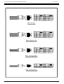
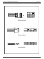
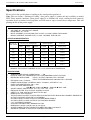
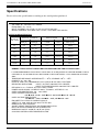
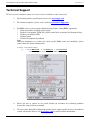
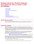
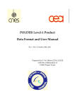
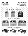
1
User Manual for Models HG2, HP2, PSM and PSL.
Version 1.0
User Manual
Product Type:
Model Name:
Switching Power Supply
HG2, HP2, PSM, PSL
June 18, 2003
Version 1.0
P/N ???
Page 1/17
User Manual for Models HG2, HP2, PSM and PSL.
Version 1.0
Table of Contents
Safety and Warnings ............................................................................3
Product and Accessories.......................................................................4
Pin Assignment ....................................................................................5
Specification…………………………………………………………..8
Operational Procedures ......................................................................12
Troubleshooting & Maintenance........................................................16
Technical Support ..............................................................................17
Page 2/17
User Manual for Models HG2, HP2, PSM and PSL.
Version 1.0
Safety and Warnings
IMPORTANT INFORMATION ON
SAFETY AND PROPER OPERATION OF THE POWER SUPPLY.
<< Read the information carefully before using it. >>
1.
Do not attempt to take apart the power supply. There are hazardous voltages inside.
2.
Do not add or remove any components from the power supply. Warranty void by doing so.
3.
Only authorized technician or service center is allowed to open the power supply for product
services.
4.
Never alter the power supply cord or plug. Improper modification can result in severe electrical
shock.
5.
Do not expose power supply to high moisture, very dusty or extreme temperature environment.
6.
Connect power supply only to designated power sources. Do not place any other materials into
the inlet of the power supply other than the power cord.
7.
Do not plug or unplug the power cord with wet hands.
8.
To avoid power cord damage, remove the power cord from the wall outlet by grabbing the plug
instead of the cord.
9.
Make sure the power cord is properly routed so that it will not be stepped on, tripped over, or
otherwise subjected to damage or stress.
10. To avoid electrical shock, unplug the unit from the power source before attempting any cleaning.
Note1:
Note2:
Note3:
For safety purposes, power cord must comply with the requirements of the National Safety Code.
All relevant registered trademarks are strictly the property of their respective companies.
No further notice will be given for any revision of the product, either modification or a newer
version.
Page 3/17
User Manual for Models HG2, HP2, PSM and PSL.
Version 1.0
Product and Accessories
Please contact your local dealers if any of the following product or accessory is missing from the
package.
1.
Power Supply Unit. (Refer to the Figure)
2.
Screws x 4.
To prevent missing screws during shipment, screws were installed on the power
supply. When install power supply into computer, remove those four screws first,
please do not remove fan or case screws. All four screws should be installed and
fasten.
3.
ATE (Auto Testing Equipment) report.
4.
User manual.
5.
Optional item – AC power cord.
Remark: All items listed above have been tested and approved; unauthorized accessories should
not be used on this product.
Note: The above figure is just a sample; please refer to the actual product.
Remark:
1. I/O switch on rear panel is only available for HG2 model.
2. The computer case shown above is not part of the power supply.
3. Screws and its specifications.
Page 4/17
User Manual for Models HG2, HP2, PSM and PSL.
Version 1.0
Pin Assignment
Always check the socket and pin assignment (for devices such as motherboard, Hard Disk etc.) before
connecting the two heads.
E
P
S
PIN
NO.
COLOR
O UTPUT
PIN
NO.
CO LOR
1
O RANGE
+3.3V
13
ORANGE
+3.3V
2
O RANGE
+3.3V
14
BLUE
-12V
3
BLACK
GND
15
BLACK
G ND
4
RED
+5V
16
GREEN
PS-ON
5
BLACK
GND
17
BLACK
G ND
6
RED
+5V
18
BLACK
G ND
7
BLACK
GND
19
BLACK
G ND
8
G REY
PW R-OK
20
W HITE
-5V
9
PURPLE
+5VSB
21
RED
+5V
10
YELLOW
+12V
22
RED
+5V
11
YELLOW
+12V
23
RED
+5V
12
O RANGE
+3.3V
24
BLACK
G ND
O UTPUT
PIN
NO.
OUTPUT
24PINS (EPS12V)
PIN
NO.
CO LOR
CO LOR
OUTPUT
1
RED
+5V
13
RED
+5V
2
RED
+5V
14
RED
+5V
3
BLACK
GND
15
BLACK
GND
4
BLACK
GND
16
PURPLE
+5VSB
5
G REEN
PS-ON
17
BLUE
-12V
6
BLACK
GND
18
BLACK
GND
7
O RANGE
+3.3V
19
ORANGE
+3.3V
8
O RANGE
+3.3V
20
ORANGE
+3.3V
9
BLACK
GND
21
ORANGE
+3.3V
10
BLACK
GND
22
BLACK
GND
11
YELLOW
+12V
23
BLACK
GND
12
YELLOW
+12V
24
YELLOW
+12V
O UTPUT
PIN
NO.
CO LOR
24PINS (AMD,ATX-GES)
PIN
NO.
COLOR
1
O RANGE
+3.3V
11
ORANGE
+3.3V
2
O RANGE
+3.3V
12
BLUE
-12V
3
BLACK
GND
13
BLACK
G ND
4
RED
+5V
14
GREEN
PS-ON
5
BLACK
GND
15
BLACK
G ND
6
RED
+5V
16
BLACK
G ND
7
BLACK
GND
17
BLACK
G ND
8
G REY
PW R-OK
18
W HITE
-5V
9
PURPLE
+5VSB
19
RED
+5V
10
YELLOW
+12V
20
RED
+5V
20PINS (ATX12V)
Page 5/17
OUTPUT
User Manual for Models HG2, HP2, PSM and PSL.
Version 1.0
PIN
NO.
EPS
COLOR
OUTPUT
PIN
NO.
COLOR
OUTPUT
1
BLACK
GND
5
YELLOW
+12V
2
BLACK
GND
6
YELLOW
+12V
3
BLACK
GND
7
YELLOW
+12V
4
BLACK
GND
8
YELLOW
+12V
8PINS (EPS12V)
PIN
NO.
COLOR
OUTPUT
PIN
NO.
COLOR
OUTPUT
1
RED
+5V
5
BLACK
GND
2
GREY
PWR-OK
6
YELLOW
+12V
3
BLACK
GND
7
YELLOW
+12V
4
BLACK
GND
8
YELLOW
+12V
8PINS (AMD,ATX-GES)
PIN
NO.
COLOR
OUTPUT
PIN
NO.
COLOR
OUTPUT
1
ORANGE
+3.3V
4
BLACK
GND
2
ORANGE
+3.3V
5
BLACK
GND
3
YELLOW
+12V
6
YELLOW
+12V
6PINS (EPS12V,OPTION)
PIN
NO.
COLOR
PIN
NO.
COLOR
OUTPUT
1
BLACK
GND
3
YELLOW
+12V
2
BLACK
GND
4
YELLOW
+12V
4PINS (ATX12V,FOR P4)
Page 6/17
OUTPUT
User Manual for Models HG2, HP2, PSM and PSL.
Version 1.0
PIN
NO.
COLOR
1~3
ORANGE
+3.3V
4~6
BLACK
GND
7~9
RED
+5V
10~12
BLACK
GND
13~15
YELLOW
+12V
OUTPUT
15PINS (SERIAL ATA HD)
PIN
NO.
COLOR
OUTPUT
PIN
NO.
COLOR
OUTPUT
1
YELLOW
+12V
3
BLACK
GND
2
BLACK
GND
4
RED
+5V
4PINS (HD/CD-ROM/RW)
PIN
NO.
COLOR
PIN
NO.
COLOR
OUTPUT
1
YELLOW
+12V
3
BLACK
GND
2
BLACK
GND
4
RED
+5V
4PINS (FLOPPY DISK)
Page 7/17
OUTPUT
User Manual for Models HG2, HP2, PSM and PSL.
Version 1.0
Specifications
Please refer to the specifications according to the actual product purchased.
Note: The new feature, “Prolonged Cooling” after power supply is remote-off only available on model
HG2. Under normal conditions, when power supply is at “Remote-off” mode, cooling fan will remain in
operation for the secondary heat dissipation, and will come to stop at a much lower temperature. This will
prolong the life of the power supply.
INPUT CHARACTERISTICS:
HG2-6300/6350/6400P
VOLTAGE: 90 ~ 240 VAC FULL RANGE.
FREQUENCY: 47 ~ 63 HZ.
INPUT CURRENT: 6/7/8.0 A (RMS) FOR 115VAC, 3/3.5/4.0 A (RMS) FOR 230VAC.
INRUSH CURRENT: 65A MAX. FOR 115 VAC, 125A MAX. FOR 230 VAC.
OUTPUT CHARACTERISTICS:
O UTPUT
VO LTAG E
O U T P U T C U R R E N T (A )
M IN .
MAX.
R E G U LA T IO N
PEAK
35
OUTPUT
LO AD
LIN E
R IP P L E & N O IS E
M A X . [P -P ]
± 5%
± 1%
50m V
+ 7 % /-5%
± 1%
12 0 m V
±5%
± 1%
15 0 m V
± 1%
15 0 m V
5V
3
12V
2
-5 V
0
0 .8
-1 2 V
0
1 .0
3 .3 V
1
25
± 5%
± 1%
50m V
+5VSB
0 .1
2
± 5%
± 1%
50m V
2 2 /2 6 /3 0
±5%
REMARK: THE OUTPUT CURRENT OF 5V & 3.3V SHOULD NOT EXCEED 45A.
SPECIFICATION:
℃
℃.
TEMPERATURE RANGE: OPERATING 0
--- 40
HOLD UP TIME: 16 ms MINIMUM AT FULL LOAD & NORMAL INPUT VOLTAGE.
DIELECTRIC WITHSTAND:
INPUT / OUTPUT 1500 VAC FOR 1 SECOND.
INPUT TO FRAME GROUND 1500 VAC FOR 1 SECOND.
EFFICIENCY: 68% TYPICAL.
POWER GOOD SIGNAL: ON DELAY 100 ms TO 500 ms, OFF DELAY 1 ms.
OVER LOAD PROTECTION: 130 +/- 20%.
OVER VOLTAGE PROTECTION:
+5V 5.7V ~ 6.5V, 3.3V 3.9 ~ 4.3V, 12V 13.6 ~ 15V.
SHORT CIRCUIT PROTECTION: +5V, -5V, +12V, -12V, +3.3V.
EMI NOISE FILTER: FCC CLASS B, CISPR22 CLASS B.
SAFETY: UL 1950, CSA 22.2 NO/ 950, TÜV IEC 950.
REMOTE ON / OFF CONTROL.
THE UNIT SHALL ACCEPT A LOGIC OPEN COLLECTOR LEVEL WHICH WILL DISABLE / ENABLE ALL
OUTPUT VOLTAGES (EXCLUDE +5V STANDBY),
AS LOGIC LEVEL IS LOW, OUTPUTS VOLTAGE WERE ENABLE,
AS LOGIC LEVEL IS HIGH, OUTPUTS VOLTAGE WAS DISABLE.
3.3V / 5V REMOTE SENSING.
COOLING: ONE 80mm BALL BEARING DC FAN.
DIMENSION: 140 (D) x150 (W) x 86 (H) mm (PS/2).
ACTIVE POWER FACTOR CORRECTION MEET IEC-1000-3-2 CLASS D.
ADVANCE THERMAL & ACOUSTICS CONTROL FEATURES.
Page 8/17
User Manual for Models HG2, HP2, PSM and PSL.
Version 1.0
Specifications
Please refer to the specifications according to the actual product purchased.
INPUT CHARACTERISTICS:
HP2-6460P/6500P
VOLTAGE: 90 ~ 264 VAC FULL RANGE.
FREQUENCY: 47 ~ 63 Hz.
INPUT CURRENT: 8.0 A FOR 115 VAC, 4.0 A FOR 230 VAC.
INRUSH CURRENT: 65 A MAX. FOR 115 VAC, 125 A MAX. FOR 230 VAC.
OUTPUT CHARACTERISTICS:
M IN .[A]
M AX .[A]
LO AD
LIN E
O U T PU T
R IPPLE & N O ISE
M AX . [P-P]
5V
2.5
40
± 5%
± 1%
60m V
12V
1.0
27~32
± 5%
± 1%
100m V
-5V
0
0.8
± 5%
± 1%
100m V
-12V
0
1.0
± 5%
± 1%
100m V
3.3V
1.0
30
+5, -5%
± 1%
60m V
+5VSB
0.1
2
± 5%
± 1%
60m V
O U TPU T
VO LT AG E
O U T PU T C U R R EN T
R EG U LAT IO N
REMARK: TOTAL OUTPUT SHOULD NOT EXCEED 460W/500W FOR HP2-6460P/6500P.
*** WHEN PERFORMING CROSS REGULATION TEST, IT IS REQUESTED TO SET THE HIGHER OUTPUT
CHANNEL AT 90% MAXIMUM AND THE LOWER OUTPUT CHANNELS AT 20% MININUM OF RATED
SPEC.
0
0
0
0
TEMPERATURE RANGE: OPERATING 0 C --- 40 C, STORAGE –20 C --- 70 C.
HUMIDITY: 10 ~ 90 % RH.
HOLD UP TIME: 16 ms MINIMUM AT FULL LOAD & 90 VAC INPUT VOLTAGE.
DIELECTRIC WITHSTAND:
INPUT / OUTPUT 1500 VAC FOR 1 MINUTE,
INPUT TO FRAME GROUND 1500 VAC FOR 1 MINUTE.
EFFICIENCY: 71% TYPICAL, AT FULL LOAD, 115VAC.
POWER GOOD SIGNAL: ON DELAY 100 ms TO 500 ms, OFF DELAY 1 ms
OVER LOAD PROTECTION: 110 ~ 150% MAX.
OVER CURRENT PROTECTION:
+5V 44 A ~ 60 A, + 3.3V 33 A ~ 45 A, 12V 35.2 A ~ 48.0 A.
OVER VOLTAGE PROTECTION:
+5V 5.7V ~ 6.5V, 3.3V 3.9 ~ 4.3V, 12V 13.6 ~ 15V.
EMI: MEET FCC CLASS B, CISPR22 CLASS B.
SAFETY: UL 1950, CSA 22.2 NO/ 950, TÜV IEC 950.
REMOTE ON / OFF CONTROL.
SHORT CIRCUIT PROTECTION: SHUTDOWN AND LATCH.
BUILT-IN ACTIVE POWER FACTOR CORRECTOR.
DIMENSION: 86(H) X 150(W) X 140 (D) mm (PS/2).
COOLING: ONE 80 mm BALL BEARING DC FAN.
Page 9/17
User Manual for Models HG2, HP2, PSM and PSL.
Version 1.0
Specifications
Please refer to the specifications according to the actual product purchased.
INPUT CHARACTERISTICS:
PSM-6550P/6600P
VOLTAGE: 90 ~ 264 VAC FULL RANGE.
FREQUENCY: 47 ~ 63 Hz.
INPUT CURRENT: 10.0 A FOR 115 VAC, 5.0 A FOR 230 VAC.
INRUSH CURRENT: 65 A MAX. FOR 115 VAC, 125 A MAX. FOR 230 VAC.
OUTPUT CHARACTERISTICS:
OUTPUT
VOLTAGE
OUTPUT CURRENT
REGULATION
OUTPUT
MIN.[A]
MAX.[A]
LOAD
LINE
RIPPLE & NOISE
MAX. [P-P]
5V
0.5
30
± 5%
± 1%
60mV
12V1
1.5
26
± 5%
± 1%
100mV
12V2
0
20
± 5%
± 1%
100mV
-12V
0
0.8
± 5%
± 1%
100mV
3.3V
0.5
30
+5, -5%
± 1%
60mV
+5VSB
0
2
± 5%
± 1%
60mV
REMARK: 12V TOTAL OUTPUT 40A MAX.
REMARK: TOTAL OUTPUT SHOULD NOT EXCEED 550W/600W FOR PSM-6550P/6600P.
*** WHEN PERFORMING CROSS REGULATION TEST, IT IS REQUESTED TO SET THE HIGHER OUTPUT
CHANNEL AT 90% MAXIMUM AND THE LOWER OUTPUT CHANNELS AT 20% MININUM OF RATED
SPEC.
0
0
0
0
TEMPERATURE RANGE: OPERATING 0 C --- 40 C, STORAGE –20 C --- 70 C.
HUMIDITY: 10 ~ 90 % RH.
HOLD UP TIME: 16 ms MINIMUM AT FULL LOAD & 90 VAC INPUT VOLTAGE.
DIELECTRIC WITHSTAND:
INPUT / OUTPUT 1500 VAC FOR 1 MINUTE,
INPUT TO FRAME GROUND 1500 VAC FOR 1 MINUTE.
EFFICIENCY: 70% TYPICAL, AT FULL LOAD, 115VAC.
POWER GOOD SIGNAL: ON DELAY 100 ms TO 500 ms, OFF DELAY 1 ms.
OVER LOAD PROTECTION: 110 ~ 150% MAX.
OVER CURRENT PROTECTION:
+5V 33 A ~ 45 A, + 3.3V 33 A ~ 45 A, 12V1 19.8 A ~ 25.2 A
12V2 19.8 A ~ 25.2 A.
OVER VOLTAGE PROTECTION:
+5V 5.7V ~ 6.5V, 3.3V 3.9 ~ 4.3V, 12V1 13.6 ~ 15V
12V2 13.6 ~ 15V.
EMI: MEET FCC CLASS B, CISPR22 CLASS B.
SAFETY: UL 1950, CSA 22.2 NO/ 950, TÜV IEC 950.
REMOTE ON / OFF CONTROL.
SHORT CIRCUIT PROTECTION: SHUTDOWN AND LATCH.
BUILT-IN ACTIVE POWER FACTOR CORRECTOR.
DIMENSION: 86(H) X 150(W) X 160 (D) mm (STRETCH PS/2, EPS12V).
COOLING: ONE 80 BALL BEARING mm DC FAN.
Page 10/17
User Manual for Models HG2, HP2, PSM and PSL.
Version 1.0
Specifications
Please refer to the specifications according to the actual product purchased.
INPUT CHARACTERISTICS:
PSL-6701P
VOLTAGE: 90 ~ 264 VAC FULL RANGE.
FREQUENCY: 47 ~ 63 Hz.
INPUT CURRENT: 10.0 / 11.0 / 12 A FOR 115 VAC, 5.0 / 5.5 / 6.0 A FOR 230 VAC.
INRUSH CURRENT: 65 A MAX. FOR 115 VAC, 125 A MAX. FOR 230 VAC.
OUTPUT CHARACTERISTICS:
MIN.[A]
MAX.[A]
LOAD
LINE
OUTPUT
RIPPLE & NOISE
MAX. [P-P]
5V
2.5
35
± 4%
± 1%
60mV
12V
1.0
45
± 5%
± 1%
100mV
-5V
0
0.8
± 5%
± 1%
100mV
-12V
0
1.0
± 5%
± 1%
100mV
3.3V
1.0
30
+5, -5%
± 1%
60mV
+5VSB
0.1
2
± 5%
± 1%
60mV
OUTPUT
VOLTAGE
OUTPUT CURRENT
REGULATION
REMARK: TOTAL OUTPUT POWER SHOULD NOT EXCEED 700W for PSL-6701P.
*** WHEN PERFORMING CROSS REGULATION TEST, IT IS REQUESTED TO SET THE HIGHER OUTPUT
CHANNEL AT 90% MAXIMUM AND THE LOWER OUTPUT CHANNELS AT 20% MININUM OF RATED
SPEC.
0
0
0
0
TEMPERATURE RANGE: OPERATING 0 C --- 40 C, STORAGE –20 C --- 70 C.
HUMIDITY: 10 ~ 90 % RH.
HOLD UP TIME: 16 ms MINIMUM AT FULL LOAD & 90 VAC INPUT VOLTAGE.
DIELECTRIC WITHSTAND:
INPUT / OUTPUT 1500 VAC FOR 1 MINUTE,
INPUT TO FRAME GROUND 1500 VAC FOR 1 MINUTE.
EFFICIENCY: 70% TYPICAL, AT FULL LOAD.
POWER GOOD SIGNAL: ON DELAY 100 ms TO 500 ms, OFF DELAY 1 ms.
OVER LOAD PROTECTION: 110 ~ 160% MAX.
OVER VOLTAGE PROTECTION:
+5V 5.7V ~ 6.5V, 3.3V 3.9 ~ 4.3V, 12V 13.6 ~ 15V.
EMI: MEET FCC CLASS B, CISPR22 CLASS B.
SAFETY: MEET UL 1950, CSA 22.2 NO/ 950, TÜV IEC 950.
REMOTE ON / OFF CONTROL.
SHORT CIRCUIT PROTECTION: SHUTDOWN AND LATCH.
REMOTE SENSING ON 3.3 V DESIGN.
MEET IEC-1000-3-2 CLASS D (ACTIVE PFC).
DIMENSION: 86(H) X 150(W) X 220 (D) mm (STRETCH PS/2).
COOLING: ONE 80 mm BALL BEARING DC FAN.
2
I C FEATURES (OPTIONAL).
Page 11/17
User Manual for Models HG2, HP2, PSM and PSL.
Version 1.0
INPUT CHARACTERISTICS:
PSL-6720P/6800P/6850P
VOLTAGE: 90 ~ 264 VAC FULL RANGE.
FREQUENCY: 47 ~ 63 Hz.
INPUT CURRENT: 5A (RMS) FOR 220 VAC
12A (RMS) FOR 110 VAC
INRUSH CURRENT: 75A MAX. FOR 110 VAC
150A MAX. FOR 220 VAC
OUTPUT CHARACTERISTICS:
OUTPUT
VOLTAGE
OUTPUT CURRENT(A)
MIN.
MAX.
+5V
0.5
+12V
REGULATION
PEAK
OUTPUT RIPPLE &
NOISE MAX. [P-P]
LOAD
LINE
45
± 5%
±1%
60mV
2
52/60/60
± 5%
±1%
120mV
-5V
0
0.8
±5%
±1%
120mV
-12V
0
0.8
±5%
±2%
120mV
+3.3V
0.5
30
±5%
±2%
60mV
+5VSB
0
3.5
±5%
±1%
60mV
REMARK: 1. TOTAL OUTPUT OF +5V AND +3.3V NOT EXCEED 230W
2. TOTAL MAX.OUTPUT 720W / 800W / 850W
SPECIFICATION:
0
0
TEMPERATURE RANGE: OPERATING 0 C --- 50 C
HOLD UP TIME: 17mS MINIMUM AT FULL LOAD & NOMINAL INPUT VOLTAGE
EFFICIENCY: 71% TYPICAL AT FULL LOAD
POWER GOOD SIGNAL: ON DELAY 100 ms TO 500 ms, OFF DELAY 1 ms
OVER POWER PROTECTION
OVER VOLTAGE PROTECTION
OVER CIRCUIT PROTECTION
SHORT CIRCUIT PROTECTOIN
EMI NOISE FILTER: FCC CLASS B, CISPR22 CLASS B
COOLING: 8 0mm DC FANS
DIMENSION: 220 (D) x 150 (W) x 86 (H) mm
Page 12/17
User Manual for Models HG2, HP2, PSM and PSL.
Version 1.0
INPUT CHARACTERISTICS:
PSL-6A00V
VOLTAGE: 90 ~ 264 VAC FULL RANGE.
FREQUENCY: 47 ~ 63 Hz.
STEADY-STATE CURRENT: 14/7A AT ANY LOW/HIGH RANGE INPUT VOLTAGE
INRUSH CURRENT: 20A MAX. FOR 110 VAC , 40A MAX. FOR 220 VAC (AT 25 DEGREE C AMBIENT
COLD START)
PFC: UP TO THE TARGET OF 95% @230V, FULL LOAD
OUTPUT CHARACTERISTICS:
OUTPUT
VOLTAGE
OUTPUT CURRENT (A)
REGULATION
OUTPUT RIPPLE &
NOISE MAX. [P-P]
MIN.
MAX.
LOAD
LINE
+5V
1
25
± 250mV
±1%
60mV
+12V1
1
50
± 600mV
±1%
120mV
+12V2
1
50
± 600mV
±1%
120mV
-12V
0
0.8
± 600mV
±1%
120mV
+3.3V
1
25
± 165mV
±1%
60mV
+5VSB
0.1
3.5
± 250mV
±1%
60mV
REMARKS:
1. +5V AND +3.3V TOTAL MAX. POWER: 170W
2. +3.3V AND +5V AND +12V2 TOTAL MAX. POWER: 600W
3. TOTAL MAX. POWER: 1000W
SPECIFICATION:
TEMPERATURE RANGE: OPERATING 0℃ -- 40℃; STORAGE TEMPERATURE: -20℃ – 80℃
HOLD UP TIME: 18mS MINIMUM AT 90V FULL LOAD & NOMINAL INPUT VOLTAGE
EFFICIENCY: 81%-86% TYPICAL AT 115V, FULL LOAD
LEAKAGE CURRENT: 3.5 mA. MAX. AT NOMINAL VOLTAGE 264VAC
POWER GOOD SIGNAL: ON DELAY 100 ms TO 500 ms, OFF DELAY 1 ms
OVER POWER PROTECTION: 110%~160%
OVER VOLTAGE PROTECTION: +3.3V→3.6~4.3V, +5V→5.5~6.5V, +12V1→13.2~15.6V, +12V2→
13.2~15.6V
OVER CURRENT PROTECTION: +3.3V→27.5~37.5A, +5V→ 27.5~37.5A, +12V1→55~75A, +12V2→55~75A
SHORT CIRCUIT PROTECTION: +3.3V, +5V, +12V1, +12V2, -12V
SAFETY: TUV, CB, CCC, RFI/EMI STANDARDS
EMI NOISE FILTER: FCC CLASS B, CISPR22 CLASS B
COOLING: 8 0mm DC FANS
I2C FEATURES (OPTIONAL)
DIMENSION: 220 (D) x 150 (W) x 86 (H) mm
Page 13/17
User Manual for Models HG2, HP2, PSM and PSL.
Version 1.0
INPUT CHARACTERISTICS:
PSL-6C00V
VOLTAGE: 90 ~ 264 VAC FULL RANGE.
FREQUENCY: 47 ~ 63 Hz.
STEADY-STATE CURRENT: 15/7.5A AT ANY LOW/HIGH RANGE INPUT VOLTAGE
INRUSH CURRENT: 20A MAX. FOR 110 VAC , 40A MAX. FOR 220 VAC (AT 25 DEGREE C AMBIENT
COLD START)
PFC: UP TO THE TARGET OF 95% @230V, FULL LOAD
OUTPUT CHARACTERISTICS:
OUTPUT
VOLTAGE
OUTPUT CURRENT (A)
REGULATION
OUTPUT RIPPLE &
NOISE MAX. [P-P]
MIN.
MAX.
LOAD
LINE
+5V
1
25
± 250mV
±1%
60mV
+12V1
1
50
± 600mV
±1%
120mV
+12V2
1
50
± 600mV
±1%
120mV
-12V
0
0.8
± 600mV
±1%
120mV
+3.3V
1
25
± 165mV
±1%
60mV
+5VSB
0.1
3.5
± 250mV
±1%
60mV
REMARKS:
1.
+5V AND +3.3V TOTAL MAX. POWER: 170W
2. +3.3V AND +5V AND +12V2 TOTAL MAX. POWER: 600W
3. TOTAL MAX. POWER: 1200W
SPECIFICATION:
TEMPERATURE RANGE: OPERATING 0℃ -- 40℃; STORAGE TEMPERATURE: -20℃ – 80℃
HOLD UP TIME: 18mS MINIMUM AT 90V FULL LOAD & NOMINAL INPUT VOLTAGE
EFFICIENCY: 81%-86% TYPICAL AT 115V, FULL LOAD
LEAKAGE CURRENT: 3.5 mA. MAX. AT NOMINAL VOLTAGE 264VAC
POWER GOOD SIGNAL: ON DELAY 100 ms TO 500 ms, OFF DELAY 1 ms
OVER POWER PROTECTION: 110%~160%
OVER VOLTAGE PROTECTION: +3.3V→3.6~4.3V, +5V→5.5~6.5V, +12V1→13.2~15.6V, +12V2→
13.2~15.6V
OVER CURRENT PROTECTION: +3.3V→27.5~37.5A, +5V→ 27.5~37.5A, +12V1→55~75A, +12V2→55~75A
SHORT CIRCUIT PROTECTION: +3.3V, +5V, +12V1, +12V2, -12V
SAFETY: TUV, CB, CCC, RFI/EMI STANDARDS
EMI NOISE FILTER: FCC CLASS B, CISPR22 CLASS B
COOLING: 8 0mm DC FANS
I2C FEATURES (OPTIONAL)
DIMENSION: 220 (D) x 150 (W) x 86 (H) mm
Page 14/17
User Manual for Models HG2, HP2, PSM and PSL.
Version 1.0
Operational Procedure
1. When removing four attached screws to install this product, please make sure not removing fan or
case screws by mistake.
2. Tighten four screws onto the computer case and double check for stability. (Please refer to the
figure on page 4).
3. Before connecting the units, make sure you verify connector and pin assignment for devices such
as motherboard, hard disk etc. For example, the pin assignments of 24-pin and 8-pin connector on
AMD Athlon MP Motherboard are totally different than Intel Xeon motherboard. Severe damages
may occur by wrong connection.
4. Check product specifications and calculate actual current requirements of each DC voltage. Make
sure these requirements fall within the minimum and maximum range of power supply. If the
current requirements are below the minimum load spec., the power supply may not start up. If the
current requirements are over the maximum load spec., our over protection circuitry will latch and
shutdown the power supply.
5. Plug in power cord to the inlet of power supply.
• Only HG2 models have line power I/O rocker switch. Please set the switch to “I” or “ON”
to turn on line power. For other models, just plug the power cord into the electrical outlet
directly.
• Active Power Factor Correction (PFC) function is available for all power supply models
listed in this manual. The PFC function ensures maximum efficiency of power usage to
preserve energy and lower your electrical bills. It also automatically adapts to a very wide
range of AC line voltage: 100V to 240V AC. (There are no manual switches for you to
select AC input). This unique design ensures you can use our power supplies anywhere in
the world.
6. You can start up the power supply remotely by using “Remote on”.
Page 15/17
User Manual for Models HG2, HP2, PSM and PSL.
Version 1.0
Troubleshooting & Maintenance
SYMPTOM
No power?
Power is on, but no
monitor display?
COUNTERMEASURE
After plug main connector, such as 24-pin or 20-pin and aux. connectors
if needed, to motherboard socket, make sure AC power cord gets AC line
source that is on wall outlet, to this product power supply. If AC power
cord gets AC line source through power bar or UPS, turn on these
devices first.
If product model is HG2, set I/O switch of power supply panel to “I” or
“ON”. Other models HP2, PSM and PSL don’t have line power I/O
rocker switch.
Boot system from computer case I/O.
Check product specifications and calculate actual current requirements of
each DC voltage. Make sure these requirements fall within the minimum
and maximum range of power supply. (i) If the current requirements are
below the minimum load spec., the power supply may not start up.
Increase load. (ii) If the current requirements are over the maximum load
spec., our over protection circuitry will latch and shutdown the power
supply. Reduce load or use larger capacity power supply.
There may be a system incompatibility or wrong connector pin out or
connection, when power supply its fan has spin for while then shutdown.
For example, (i) Use wrong pin assignments of 24-pin and 8-pin
connectors e.g. For AMD Athlon MP Motherboard connectors are totally
different than Intel Xeon motherboard. Severe damages may occur by
plugging wrong connection. (ii) Plug wrong pin position on small 4-pin
floppy drive connector to cause connection displacement.
[Action] Remove all connectors at all first, then one-by-one to plug in
one connector at a time and verify the operation of each device and
system function. When no problem, proceed next device.
The power supply could be latched by self-protection function (e.g. “over
voltage”, “over current”, “overload”). Remove the power cord, wait for
20 seconds or more to discharge its electricity, then plug in the power
cord again, try to restart the computer.
Check if video card is seated properly; check the video cable connection.
Verify system and motherboard requirements. For example, some
motherboards require RAM in pairs to work properly, such as Tyan
#S2665.
Page 16/17
User Manual for Models HG2, HP2, PSM and PSL.
Version 1.0
Technical Support
To best serve our customers, there are several services available to suite your needs:
1.
For detailed products specification: please visit www.zippy.com
2.
For technical enquiries: please send e-mail to [email protected]
3.
For RMA service: please prepare following items before calling RMA department,
Proof of purchase (original dated receipt)
Product serial number (SER. NO.) (Refer to the label on product and diagram below)
Product part number (P/N)
Product model
Detailed description of problems
Note:
Different distributors or resellers have their specific RMA terms and conditions; please
contact them for detailed information.
()
()
()
Locations of relevant information:
e.g.
1 Model HP2-6460P, 2 S/N T3240001, 3 P/N 2000370018.
Actual contents may not be the same for different models.
4.
Please feel free to contact us via e-mail should you encounter any technical problems
beyond the scope of this user manual.
5.
We carry more than 120 standing high quality power supply models and over six hundred
various sub-models. Please visit www.zippy.com for more detailed information.
Page 17/17