1
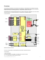
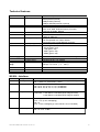
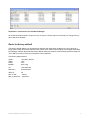
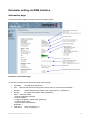
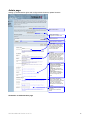
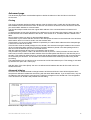
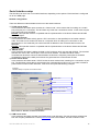
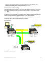
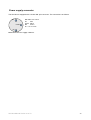
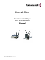
bintec WI-Client
WLAN Ethernet Client Adapter
WLAN Serial Client Adapter
Manual
WI-Client Manual Version 2.16 V3
1
Content:
Overview..........................................................................................................................................................3
Technical features:.......................................................................................................................................5
WLAN - Interface:.......................................................................................................................................5
First Time Setup ..............................................................................................................................................6
The ComPoint Manager...............................................................................................................................6
Reset to factory default................................................................................................................................7
Parameter setting via WEB interface..............................................................................................................8
Information page..........................................................................................................................................8
Access Point page .......................................................................................................................................9
Security page................................................................................................................................................11
Admin page..................................................................................................................................................12
Advanced page.............................................................................................................................................13
Cloning.....................................................................................................................................................13
Advanced bridging...................................................................................................................................13
Roaming...................................................................................................................................................14
Ethernet Port............................................................................................................................................14
DHCP-Relay-Agent.................................................................................................................................14
Serial interface setup....................................................................................................................................16
Comment to the multicast settings...........................................................................................................17
Power supply connector..............................................................................................................................20
Legal Notice.................................................................................................................................................21
Pictures:
Illustration 1 Block schematic.........................................................................................................................3
Illustration 2 Connections and LEDs..............................................................................................................4
Illustration 3 arrangement to configure the WI-Client....................................................................................6
Illustration 4 screenshot of the ComPoint Manager........................................................................................7
Illustration 5: Information page......................................................................................................................8
Illustration 6: Access Point page.....................................................................................................................9
Illustration 7: Wireless page............................................................................................................................10
Illustration 8: Security page............................................................................................................................11
Illustration 9: Administration page.................................................................................................................12
Illustration 10: Configuration example...........................................................................................................13
Illustration 11: Advanced page........................................................................................................................15
Illustration 12: Windows TCP/IP Portmonitor................................................................................................16
Illustration 13: Multicast-mode.......................................................................................................................17
Illustration 14: Serial interface setup..............................................................................................................19
Illustration 15: Power supply connector.........................................................................................................20
WI-Client Manual Version 2.16 V3
2
Overview
The WI-Client is intended to connect devices with ethernet or serial interfaces to a Wireless Local Area
Network (WLAN) corresponding to the 802.11 a/b/g standard. The WI-Client connects over the ethernet
interface all devices in its LAN segment with a LAN that is accessible over WLAN.
The WI-Client can receive and transmit data over its serial port which are exchanged over LAN or WLAN
with other devices, i.e. annother WI-Client or a computer with a suitable software.
Functional blocks:
RS232
RI
6
DTR
4
DSR
8
RTS
7
CTS
2
TxD
3
RxD
32bit
PCI
9
SER1
DCD
miniPCISocket
A2
UART
1
RS232
miniPCI
radio module
CM9
A1
Network
Processor
UBICOM
IP3023
WD
32bit Reset
250MHz
4MByte Flash
Reset/
Watchdog
MEM
Reset
LAN
1
TD-
2
TD+
3
RD-
6
RD+
SPI
RJ45
10/100Mbit
Phy.
Auto MDIX
Eth.
MAC
M II
EEPROM
SER2
SER1
P
O
R
T
3.3V
LAN
WLAN
1.2V
3.3V
Power
9 - 36V
< 3W
+
-
DC/DC
Converter
DC/DC
Converter
Power
Illustration 1 Block schematic
The core of the WI-Client is a 32bit network processor that controls all functions.
The interfaces:
1) Mini-PCI-Socket
2) Ethernet-Interface 10/100 MBit + auto MDI (auto crossover function)
3) 1 or 2 serial interfaces with 6 status lines each
WI-Client Manual Version 2.16 V3
3
The ethernet port has a RJ45 plug. Because of the auto MDI functionality the WI-Client can be attached to a
HUB or the LAN port of a computer with standard patch cables. The WI-Client recognizes the cable polarity
and automatically connects the right signal lines.
The serial port is a 9 pin female D-SUB connector. The pinout makes it possible to connect to a computer
COM port with a 1 to 1 serial cable, the exact pinout is shown in Illustration above.
The power supply should be 9 – 35VDC / 3W. At 12VDC the input current is typical 250mA.
Back and front view:
RP-SMA antenna connector
Option for a 2. antenna connector
N
et
e s er2 e r1 A N LA n
R S S L W O
0V
+ VB
NC
5 4 3 2 1
9 8 7 6
LINK
PIN
1
2
3
4
5
6
7
8
9
Function
DCD
TxD
RxD
DSR
GND
DTR
CTS
RTS
RI
Dir.
IN
OUT
IN
IN
OUT
IN
OUT
IN
100MBit
Illustration 2 Connections and LEDs
LED
On
WLAN
LAN
Ser1 (2)
WI-Client Manual Version 2.16 V3
Function
Green
Red blinking
Steady green
always on when power is on
searching for RF-connection (scanning)
found a suitable Access-Point and established
a connection
Green blinking 802.1x Authentification is in process
Green + red blinking
RF activity (receive or transmit)
Off
no link is recognized
Green
link is established with another LAN device.
Green + red blinking
activity on the LAN interface
Off
interface is inactive or not connected to the
other (W)LAN-.communication side
Green
connected to other serial device.
Green + red blinking
activity on the serial interface (receive or
transmit)
4
Technical features:
Processor
Type
Memory
Interface
Ethernet
Serial 1
Serial 2
Mini-PCI
Relay (optional)
AUX input (optional)
LEDs
LEDs
Power supply
Connector
Power consumption
Voltage range
Circular M8-3pin connector with screw locking
< 2.5W (typ.) < 3W (max.)
Standard: 8-30V non isolated
operating 0 - 70°C ( 32 - 158°F)
storage -20 - 80°C ( -4 - 176°F)
Board
Case
Weight
120x100x20mm
standard: 125x105x40mm
approx. 500g
Temperature
range
Dimensions
32bit network processor 250MHz clock
256KByte program (internal)
64KByte data (internal)
4MByte flash (external)
4MByte SDRAM (external, optional)
10/100 Mbps fast ethernet auto MDI/MDIX
RS232 with control lines
RTS, CTS, DSR, DTR,DCD (input), RI (input)
(optional as RS485, RS422)
Same as serial 1 but only RS232
Socket for RF cards with Atheros chipsets
(AR5112, AR5113)
Relay contact
can be operated over LAN or WLAN
Connection with circular M8-4pin connector
Isolated input with optocouple
- Power (green)
- WLAN (green, red)
- LAN (green, red)
- SER1 (green, red)
- SER2 (green, red)
WLAN - Interface:
WLAN
Encryption
Security
Data rates
64, 128bit WEP, AES
802.11i WPA + WPA2 (Wifi Protected Access) (PSK/TKIP)
802.1x (EAP-TLS, EAP-PEAP), LEAP
802.11b 11, 5,5, 2 & 1 MBit/Sec.
802.11g 54, 48, 36, 24, 18, 12, 9, 6 MBit/Sec.
802.11a 54, 48, 36, 24, 18, 12, 9, 6 MBit/Sec.
Frequencies
ISM band: 2.400 MHz to 2.483 MHz
U-NII band: 5.150 MHz to 5.350 MHz (ETSI, RegTP indoor)
5.470 MHz to 5.725 MHz (ETSI, RegTP outdoor)
Channels
802.11b/g:
ETSI: 1-13, (3 non overlapping)
802.11a:
ETSI: 12 non overlapping (5.150-5.350 & 5.470-5.725 MHz)
Power output
802.11b/g: 18dBm peak
802.11a: 18 or 17dBm
WI-Client Manual Version 2.16 V3
5
First Time Setup
To set up the WI-Client it has to be connected with a patch cable to the ethernet interface of a computer.
Because of the auto MDI/MDIX capability, you can use a straight or crossover patch cable.
After applying power, the green “Link LED“ on the RJ45 connector shines when a link is detected. The yellow
“100 MBit LED“ indicates whether the connection is capable of 100 MBit.
The “LAN” LED on the front panel shines green when a connection has been established over the ethernet.
The “WLAN” LED on the front panel will be blinking red because usually no suitable WLAN is recognized.
The ComPoint Manager
To do the „first time setup“ the WI-Client has to be connected via the LAN-Interface to the computer (PC) that
runs the ComPoint Manager Program.
9-35V DC
R
es
Se
r
Se 1
L r2
A
W N
L
O AN
n
Ethernet
Notebook
/
Computer
A nt1
A nt2
W i - C lie n t
Illustration 3 arrangement to configure the WI-Client
You have to observe:
- The connected PC should have an fixed IP address. (no DHCP)
-
The LAN-Interface at the PC must be detected as connected. Check the parameter of the LANInterface with the „ipconfig“-command.
-
If the LAN-Interface of the PC is correctly recognized then press the „refesh“-button of the WI-Clientconfig-program.
An active firewall could prevent the communication the WI-Client.
-
For detection of the WI-Client and managing of the IP address the CD Rom contain a small tool, this tool is
called ComPoint Manager.
After the start the ComPoint Manager ascertained all network interfaces that are active at the PC. After that
the ComPoint Manager sends broadcast UDP requests to all these Interfaces. The registered answers of the
WI-Client devices are shown in a list.
WI-Client Manual Version 2.16 V3
6
Illustration 4 screenshot of the ComPoint Manager
All located WI-Client-Devices are shown in list. A click to a device opens a sub window to change the unit
name and the IP address.
Reset to factory default
The factory default settings can be restored by pressing the reset button located on the front panel for a
longer period. After about 5 seconds the LEDs “SER1“ and “SER2“ starts blinking red and green alternately.
By keeping the button depressed the factory default values are restored. After finishing all LEDs except the
“ON” LED are turned off. Now the reset button can be released.
main factory default values:
SSID =
WEP =
WPA =
MODE=
“WI-Client_WLAN“
OFF
OFF
802.11b/g
IP =
Netmask =
192.168.0.252
255.255.255.0
SER1+2 :
off
802.1x user:
„admin“
802.1x password: „password“
WI-Client Manual Version 2.16 V3
7
Parameter setting via WEB interface
Information page
General information regarding firmware versions and status reports
Illustration 5: Information page
On the left hand side are links to different setup and info pages.
•
•
Information
the page above(Illustration )
APs
Shows a table with all access points currently seen by the WI-Client (Illustration ).
•
•
•
Wireless
WLAN interface setup (SSID, mode, frequencies etc.) (Illustration )
Security
Encryption setup (WPA, WEP) (Illustration )
Admin - reboot WI-Client
- reset all parameters to default.
- firmware updates
- configure IP-address, subnet mask, gateway IP
- configure setup options
- enter username and password
(Illustration )
serial Port 1
setup of serial port 1 ()
serial Port 2
setup of serial port 2
•
•
WI-Client Manual Version 2.16 V3
8
Access Point page
Information on all access points currently available to the WI-Client.
Illustration 6: Access Point page
WI-Client Manual Version 2.16 V3
9
Wireless page
Configuring the WLAN interface
The WLAN radio can be switch off or
here.
Wireless mode
Infrastructure = Connect to AP
Ad hoc = peer to peer connection
SSID, Service Set Identifier.
Name of the WLAN network.
This name must be the same as the
access points SSID
Transmission rate.
Best = automatic depending on signal
strength.
If useful, you can select a fixed
bitrate.
The Transmit Power can be adjusted
here.
802.11 mode.
802.11b = 2.4GHz 11MBit
802.11g = 2.4GHz 54MBit
802.11b/g = 2.4GHz 11 + 54MBit
802.11a = 5GHz 54MBit
AP Density:
influences the roaming behaviour
Super mode: is not supported
Country
Select the country in which the
ESCG is used. This determines the
number of available channels.
Antenna mode
single = when one antenna is used
diversity = when two antennas are
used. With two antennas the radio
can select the antenna that delivers
the best signal.
802.11a Frequency Bands:
possible channel restriction for the 5GHz
(802.11a) operation.
Channel
This channel has to be selected
in ad hoc mode only
Illustration 7: Wireless page
By clicking the “Save“ button all changes on this page are stored. Use “Cancel” to undo any changes. After
clicking “Save” the program prompts the user to make a reboot. This should be done after all necessary
changes on all pages have been made.
WI-Client Manual Version 2.16 V3
10
Security page
Setting up the security options
If the user selects the 802.1x authentication the PSK or the WEP-Keys don’t have to be defined because the
WI-Client and the Radius-Server will determine these parameters automatically.
Enable authentication with radius
server
Select authentication method:
EAP-PEAP
EAP-TLS
EAP-TTLS
LEAP (CISCO spec.)
Username and Password
Enable WPA and select WPA
mode
WPA = encryption with RC4
WPA2 = encryption conforming to
AES
Select cipher type
PSK = Pre Shared Key
for authentication
with access point
Default WEP key for data
transmission
Authentication type for registration
with an access point
WEP key length
64 bit or 128 bit
Enter keys as hex digits
10 digits for 64 bit WEP
26 digits for 128 bit WEP
There must be defined at least one
key that is defined as „default
WEP key“
Illustration 8: Security page
WI-Client Manual Version 2.16 V3
11
Admin page
Setting up administration rights and configure basic features, update firmware
Reboot the Wi-Client
Restore the Wi-Client
configuration to default values
Select firmware file
Upload firmware to Wi-Client
Wi-Client
Device name:
This is a name to identify the WiClient by external configuration
and IP address lookup programs,
i.e. the locator program.
This is not the SSID
IP address:
By selecting “DHCP” the Wi-Client
is assigned the IP address from a
DHCP server on the network.
By selecting “Static” the IP
address is fixed. In this case the
network mask has to be definded
and possibly the default gateway.
Enable more configuration options:
IP Config over UDP 41233:
assignment of an IP-Address over
the LAN-Interface (special
function).
Telnet-Config: Configuration
option via an telnet server socket
(TCP-Port 23).
disable wireless config: for
security reasons it is possible to
prevent the configuration via
WLAN.
Option to block the bridging
funktion of the Wi-Client. This
could be useful when the Wi-Client
only works as a serial client
adapter. The configuration via
LAN-Interface is not blocked with
this option.
Enter user name and password to
protect the
Wi-Client from unauthorized
access
Illustration 9: Administration page
WI-Client Manual Version 2.16 V3
12
Advanced page
The advanced page offers more detailed options to define the behavior of the WI-Client in the WLAN
environment.
Cloning
The cloning parameter defines the MAC address of the WI-Client’s radio. Usually the WI-Client leaves the
MAC address at the manufacturers value. All devices connected to the WLAN over the WI-Client’s ethernet
port use this MAC address for communication.
The WI-Client keeps a table where the original MAC address of the connected device is linked to its IP
address.
If a data package arrives at the WI-Client on the ethernet port, the WI-Client first checks if there is an entry in
its table with the source MAC address of this device. If the answer is no, this MAC address is added to the
table.
Next it checks if there is an entry for the target MAC address.
If the answer is yes it means that the receiver of this data packet is located on the wired side of the WI-Client
and therefore there is no need to send it over the wireless radio.
If the answer is no, the source MAC address is replaced by the radio’s MAC address and the data package
is sent over the radio to the WLAN
If the WI-Client receives a data package from the WLAN, it first extracts the target IP address. Next it looks
up the corresponding MAC address in its table. This MAC address is placed in the data package which is
then sent over the ethernet port to the connected devices.
With this method several devices can be connected to the WI-Client.
This procedure only works in LAN’s / WLAN’s that use the IP protocol. If other protocols are used, the WIClient can be forced to transfer the MAC address of the first data packet that arrives on the ethernet port to
the radio. This method is called cloning. It ensures that all data packages intended for the connected device
are received by the WI-Client. The WI-Client can forward the data to the ethernet port without any further
processing.
This method allows only one device to be connected to the WI-Client ethernet port. This strategy is activated
by selection the option “Eth. Client (var)”.
With the option “Eth. Client (fixed)” the user can defined a MAC address that the WI-Client will use for the
WLAN Connection.
Advanced bridging
Check this box to disable the data exchange between WI-Client and WLAN. Some WLAN-Systems don't
accept that 2 different IP addresses are working with the same MAC-Address. If you check this box, only the
IP-Address of the Client that is connected to the LAN-Port will appear on the WLAN side. The configuration
of the WI-Client over WLAN is still possible with this setting.
Illustration 10: Configuration example
WI-Client Manual Version 2.16 V3
13
Roaming
Roaming is the term for automatically changing to another access point when the WI-Client recognizes a
decreasing RF signal level when leaving the covered area of the current access point and a better level with
another AP available.
For this purpose the WI-Client keeps a table with a list of access points from which it is receiving signals
(beacons).
To receive these beacons the WI-Client has to tune to the different channels and listen for incoming signals
for a certain amount of time. This hampers the regular data traffic which the WI-Client has to process.
Therefore this procedure is handled in different ways depending on the current signal level.
To make this procedure even more effective, the user can restrict the channels where the WI-Client is
allowed to look for beacons of other access points
Ethernet Port
Check this option to enable manual settings for the ethernet port.
DHCP-Relay-Agent
Check this option to enable the DHCP-Relay-Agent of the WI-Client. This is useful if the connected clients at
the ethernet port of the WI-Client are using DHCP.
WI-Client Manual Version 2.16 V3
14
Illustration 11: Advanced page
WI-Client Manual Version 2.16 V3
15
Serial interface setup
The WI-Client can have one or two serial interfaces, depending on the options. Each interface is configured
on its own WEB page.
Network configuration
There are different modes available for the use of the serial interfaces:
1) TCP/IP server mode:
In this mode the WI-Client opens a socket in a “listen mode”, which means that it is waiting on a certain
port (local port) for a connection. The WI-Client only holds one connection at a time. In this mode only the
port number has to be specified.
Remark: This operation mode is compatible with the implementation of the bintec Wix040 and Wix065
Rel.7.8 or higher.
2) TCP/IP client mode:
In this mode the WI-Client actively opens a TCP connection on the specified port of another network
node. This node can be another WI-Client or a computer which is waiting for a connection on the
specified port. In this mode the port number and the IP address of the connected device have to be
specified.
Remark: This operation mode is compatible with the implementation of the bintec Wix040 and Wix065
Rel.7.8 or higher.
3) UDP/IP mode:
In this mode the WI-Client is waiting for data on the “local port“ which are sent with UDP/IP. The received
data are then sent to the “remote port” of the remote IP address. The UDP should be used in
circumstances where the communication between the devices is frequently interrupted. It should be
considered though that the UDP protocol does not guarantee the correct transfer of data.
4) Printer server mode:
In this mode the WI-Client starts a TCP/IP socket in server mode which is waiting for a connection on port
515. The WI-Client is then able to execute print jobs corresponding to RFC1179. If you want to enable a
printer with this method under Windows, it has to be set up like the following example:
Example:
Windows setup for a printer connected via LPR
IP address ESCG
Protocol
Portnumber: LPD is always 515
Name: ignored by Wi-Client
Illustration 12: Windows TCP/IP Portmonitor
5) COM server mode:
In this mode the WI-Client provides virtual COM ports under Windows. For this purpose a software tool
from the company Wiesemann & Theis (www.wut.de) has to be installed. The tool is named “COM
WI-Client Manual Version 2.16 V3
16
Umlenkung. This tool enables the WI-Client to connect to serial devices over LAN/WLAN. After
installation of the software enter the WI-Client IP address and port number.
Please read and following the license terms of the tool.
Comment to the multicast settings
In the Multicast-Mode serial busmembers who are communicating with RS485 interfaces can be connected
via the (W)LAN. Depending which task the serial device takes it is possible to configure different modes:
1. Slave
2. Master
3. Multimaster
As a slave the WI-Client receives data on the configured multicast address and sends this data to the serial
interface. Data that is received from the serial line is sent to the given unicast IP address.
As a master the WI-Client receives data from the unicast IP address and transmits data to the multicast IP
address.
In multimaster mode all transfers are done via the multicast IP address.
sample application:
RS232/
RS485
RS232/
RS485
PC
MASTER
Unicast 192.168.170.100 Port 8888
192.168.170.100
8888
8889
224.0.0.42
IP:
Local Port:
RemotePort:
Multicast:
Unicast 192.168.170.100
Port 8888
IP:
Local Port:
RemotePort:
Multicast:
SLAVE
1
Multicast 224.0.0.42 Port 8889
Wi-Client
192.168.170.102
8889
8888
224.0.0.42
RS232 / RS485
Device
Wi-Client
IP:
Local Port:
RemotePort:
Multicast:
RS232/
RS485
192.168.170.101
8889
8888
224.0.0.42
RS232 / RS485
Device
SLAVE
2
Wi-Client
Illustration 13: Multicast-mode
WI-Client Manual Version 2.16 V3
17
“Keep alive“ settings
A TCP/IP connection remains open after being established until one of the communicating devices closes
the connection. If the physical connection between the WI-Client and the other device is interrupted without
closing the TCP/IP connection, there is a possibility that the WI-Client is not able to reconnect. The TCP/IP
socket can be programmed to send an empty data package to the communication partner in regular intervals
(keep alive period). If the communication partner supports this mode, it sends a corresponding answer. This
answer is proof that the connection is still intact. If there is no answer for a number of times (keep alive
probes), the TCP/IP connection is closed and the WI-Client starts the TCP/IP socket again.
“Send trigger” configuration
The data received by the WI-Client are first temporarily stored. There are different criteria when the stored
data will be sent over the LAN/WLAN.
1) Byte trigger: The user defines a number of Bytes. After reaching that number, the stored data are
sent.
2) Timeout: After receiving a character a timer with the programmed value is started. Each received
character restarts the timer. Once the timer has elapsed the stored data are sent.
3) Delimiter: The user defines a certain character. When this character is received, the stored data are
sent.
The parameter “receive fifo size” defines the quantity of bytes that can be stored in a ringbuffer before the
data is sent to the (W)LAN interface. If you use the WI-Client in an application that receives permanently
data via the serial interface the “receive fifo size” has to be set to a value between 1024 and 2048 bytes.
Because the WI-Client needs all the available RAM memory in a situation of authentication with 802.1x
(PEAP,TLS) this value is set to a value of 256 Bytes by default to save memory space.
Handshake mode
This defines how the communication partners are signaling their ability to send and receive data. With the
status lines RTS and DTR the WI-Client reports that it is ready to receive. The status lines CTS and DTR are
inputs where the communication partner reports its readiness to receive. The signals DCD and RI can be
forwarded to the WI-Clients LAN/WLAN communication partner.
The WI-Client be controlled remote or local to handle the data flow.
The following modes are available to the user:
1) no handshake: The CTS/DSR signals are not utilized. CTS/RTS are set to active when the serial
interface is connected over the LAN/WLAN.
2) XON / XOFF : The WI-Client sends and receives the control characters XON = 0x11 and XOFF =
0x13. The WI-Client sends a XOFF to his serial communication partner when the memory buffer is
almost full and a XON when it is almost empty.
3) RTS/CTS: The WI-Client signals that it is ready to receive over the RTS line and recognizes the CTS
signal to determine if its serial partner is ready to receive.
4) DTR/DSR: The WI-Client signals that it is ready to receive over the DTR line and recognizes the
DSR signal to determine if its serial partner is ready to receive.
5) Remote: In this mode the WI-Client transmits the state of the status lines CTS, DSR, RI and DCD to
its LAN/WLAN communication partner. This happens over a different socket (port). This makes it
necessary for the user to enter more specifications.
The state of the status lines are described by strings of letters.
A capital letter means the signal is active, a small letter means inactive.
’D’ = DSR active
‘d’ = DSR inactive
’R’ = CTS active
‘r’ = CTS inactive
’C’ = DCD active
‘c’ = DCD inactive
’I’ = DSR active
‘i’ = DSR inactive
The WI-Client interprets the received data as follows:
’D’ -> set DTR to active
‘d’ = set DTR to inactive
’R’ -> set RTS to active
‘r’ = set RTS to inactive
‘C’ or ‘c’ and ‘I’ or ‘i’ are ignored.
WI-Client Manual Version 2.16 V3
18
6) 3964R: This is a special protocol which is commonly used for communication with SPS
(programmable control systems). This protocol uses special characters and events to signal when it
is ready to transmit and receive. Descriptions of this protocol are available in literature.
Illustration 14: Serial interface setup
WI-Client Manual Version 2.16 V3
19
Power supply connector
The WI-Client is equipped with a circular M8- 3pin connector. The connection is as follows:
NC
8-30V
M8 cable wire colors:
0V
blue
8-30V black
NC
brown
NC = not connected
0V
Illustration 15: Power supply connector
WI-Client Manual Version 2.16 V3
20
Legal Notice
Aim and purpose
This document is part of the user manual for the installation and configuration of funkwerk devices. For
the latest information and notes on the current software release, please also read our release notes,
particularly if you are updating your software to a higher release version. You will find the latest release
notes under www.funkwerk-ec.com .
Liability
This manual has been put together with the greatest possible care. However, the information contained
in this manual is not a guarantee of the properties of your product. Funkwerk Enterprise Communications
GmbH is only liable within the terms of its conditions of sale and supply and accepts no liability
for technical inaccuracies and/or omissions.
The information in this manual can be changed without notice. You will find additional information and
also release notes for funkwerk devices under www.funkwerk-ec.com .
Funkwerk devices make WAN connections as a possible function of the system configuration. You
must monitor the product in order to avoid unwanted charges. Funkwerk Enterprise Communications
GmbH accepts no responsibility for data loss, unwanted connection costs and damage caused by
unintended
operation of the product.
Trademarks
funkwerk trademarks and the funkwerk logo, bintec trademarks and the bintec logo, artem trademarks
and the artem logo, elmeg trademarks and the elmeg logo are registered trademarks of Funkwerk Enterprise
Communications GmbH.
Company and product names mentioned are usually trademarks of the companies or manufacturers
concerned.
Copyright
All rights reserved. No part of this manual may be reproduced or further processed in any way without
the written consent of Funkwerk Enterprise Communications GmbH. The documentation may not be
processed and, in particular, translated without the consent of Funkwerk Enterprise Communications
GmbH.
You will find information on guidelines and standards in the declarations of conformity under
www.funkwerk-ec.com .
How to reach Funkwerk Enterprise Communications GmbH
Funkwerk Enterprise Communications GmbH, Südwestpark 94, D-90449 Nuremberg, Germany,
Phone: +49 180 300 9191 0, Fax: +49 180 300 9193 0
Funkwerk Enterprise Communications France S.A.S., 6/8 Avenue de la Grande Lande, F-33174
Gradignan, France, Phone: +33 5 57 35 63 00, Fax: +33 5 56 89 14 05
Internet: www.funkwerk-ec.com
WI-Client Manual Version 2.16 V3
21