1
TT™5800X/TT™2400X
Gateway
User Manual
802.11a
802.11b/g
All Rights Reserved. Copyright 2006 Teletronics International, Inc.
2 Choke Cherry Road, Rockville, MD 20850 Tel: 301.309.8500 Fax: 301.309.8851
Table of Contents
Disclaimers ………………………….………….….…….……….….………........3
Introduction ……………………………………………………………………….4
Product Features ………………………………………………………………...5
Product Specifications ………………………………………………………….5
Installation ………………………………………………………………..………10
Configuring windows for IP Networking ……………………………………11
Web Configuration Interface …………………………………………………..15
Appendix A: Warranty Policy …………………………………………………..50
Appendix B: RMA Policy ………………………………………………………..51
Appendix C: Regulatory Information …………………………………………52
Appendix D: Contact Information ……………………………………………..54
Appendix E: WDS Explained ……………………………………….…………..55
Appendix F: Antenna Diversity …………………………………….…………..57
Appendix G: Troubleshooting ………………………………………………….58
Appendix H: Glossary ……………………………………………………………59
All Rights Reserved. Copyright 2006 Teletronics International, Inc.
2 Choke Cherry Road, Rockville, MD 20850 Tel: 301.309.8500 Fax: 301.309.8851
Disclaimers
No part of this documentation may be reproduced in any form or by any means or used to make any derivative work (such as
translation, transformation, or adaptation) without written permission from the copyright owner.
All the other trademarks and registered trademarks are the property of their respective owners.
Statement of Conditions
We may make improvements or changes in the product described in this documentation at any time. The information
regarding to the product in this manual are subject to change without notice.
We assumes no responsibility for errors contained herein or for direct, indirect, special, incidental, or consequential damages
with the furnishing, performance, or use of this manual or equipment supplied with it, even if the suppliers have been advised
of the possibility of such damages.
Electronic Emission Notices
This device complies with Part 15 of the FCC Rules. Operation is subject to the following two conditions:
(1)This device may not cause harmful interference.
(2)This device must accept any interference received, including interference that may cause undesired operation.
FCC INFORMATION
The Federal Communication Commission Radio Frequency Interference Statement includes the following paragraph:
The equipment has been tested and found to comply with the limits for a Class B Digital Device, pursuant to part 15 of the
FCC Rules. These limits are designed to provide reasonable protection against harmful interference in a residential
installation. This equipment usage generates radio frequency energy and, if not installed and used in accordance with the
instructions, may cause harmful interference to radio communication. However, there is no grantee that interference will not
occur in a particular installation. If this equipment does cause harmful interference to radio or television reception, which can
be determined by turning the equipment off and on, the user is encouraged to try to correct the interference by one or more of
the following measures:
•
Reorient or relocate the receiving antenna.
•
Increase the separation between the equipment and receiver.
•
Connect the equipment into an outlet on a circuit different from that to which the receiver is connected.
•
Consult the dealer or an experienced radio/TV technician for help.
The equipment is for home or office use.
IMPORTANT NOTE
FCC RF Radiation Exposure Statement: This equipment complies with FCC RF radiation exposure limits set forth for an
uncontrolled environment. This equipment should be installed and operated with a minimum distance of 20cm between the
antenna and your body and must not be co-located or operating in conjunction with any other antenna or transmitter.
Caution: Changes or modifications not expressly approved by the party responsible for compliance could void the user's
authority to operate the equipment.
All Rights Reserved. Copyright 2006 Teletronics International, Inc.
2 Choke Cherry Road, Rockville, MD 20850 Tel: 301.309.8500 Fax: 301.309.8851
Introduction
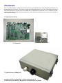
The TT™5800X gateway is Teletronics’s answer to the ever growing demand for higher bandwidth and security in a
wireless network environment. It is based on a brand new redesigned platform that not only offers faster performance
and capacity but also the support all current pre IEEE 802.11i wireless security standards. The TT™5800X is the IEEE
802.11a version of the platform that directly targets the need to those that requires the more secure, less crowded 5.8
GHz frequency spectrum.
TT™5800X Product Photos
TT™5800X PCB
IEEE 802.11a miniPCI Card
TT™5800X Enclosure (NEMA4 Box)
All Rights Reserved. Copyright 2006 Teletronics International, Inc.
2 Choke Cherry Road, Rockville, MD 20850 Tel: 301.309.8500 Fax: 301.309.8851
Product Features
•
•
•
•
•
•
•
•
•
•
•
Compact size for small enterprise or system integrate service market
Compliant with IEEE 802.11a specifications
Supports 64/128-bit WEP, WPA and IEEE802.1x
Supports Atheros Super A (up to 108Mbps)
Intelligent firmware upgrade via Web browser
Built-in Web-based utility for easy configuration from any Web browser
Support POE (IEEE 802.3af) function
Supports wireless bridging and MAC address filtering
Super bright LED indicating status and signal level (RSSI)
Provide 10/100M, auto sensing MDI/MDI-X Ethernet port
EzManager Support
*Atheros Super G (Proprietary technology of Atheros Communication Inc.) would only work in situations where both
ends of the communication link are using the Atheros radio chipset.
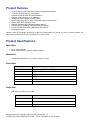
Product Specifications
Main Chips
•
•
CPU: Ubicom IP3023
Radio: Supports 802.11a Atheros AR5213+AR5112
Mechanical
•
Chassis Dimension (W x D x L): 161mm x 30mm x 119mm
Board Spec
Specification
Description
Network Standard
IEEE 802.11 a, IEEE 802.3, IEEE802.3x
Ethernet
10/100BaseT Ethernet, Auto MDI/MDI-X
Network Architecture
Infrastructure; Ad-Hoc; AP
MAC
CSMA/CA
Status Indicators
POWER, Wireless LAN, and Ethernet LAN
Push Button
Reset to Default Button
Radio Spec
•
IEEE 802.11a 5 GHz mini-PCI card
Specification
Description
Chipset
MAC/BB Processor Atheros AR5213 RF Chip Atheros AR5112
Power Consumption
IEEE 802.11a TX: ~1000 mA RX: ~400 mA
Antenna Connector
N-type Female
All Rights Reserved. Copyright 2006 Teletronics International, Inc.
2 Choke Cherry Road, Rockville, MD 20850 Tel: 301.309.8500 Fax: 301.309.8851
Output Power
•
•
•
•
16dBm (± 2dB) @ 54Mbps
17dBm (± 2dB) @ 48Mbps
18dBm (± 2dB) @ 36Mbps
19dBm (± 2dB) @ 6 Mbps
IEEE 802.11a Sensitivity @ 10% Packet Error Rate
Receiver Sensitivity
•
•
•
•
•
•
•
•
54Mbps: -70dBm
48Mbps: -71dBm
36Mbps: -75dBm
24Mbps: -79dBm
18Mbps: -82dBm
12Mbps: -84dBm
9Mbps: -86dBm
6Mbps: -87dBm
IEEE 802.11a (OFDM)
Modulation
Operating Frequency
•
•
•
•
48/54 Mbps (QAM-64)
24/36 Mbps (QAM-16)
12/18 Mbps (QPSK)
6/9 Mbps (BPSK)
•
USA(FCC): 5.15GHz ~ 5.25GHz, 5.25GHz ~ 5.35GHz, 5.47
GHz ~ 5.725 GHz, 5.725 GHz ~ 5.825 GHz
Europe(ETSI): 5.15 GHz ~ 5.35 GHz, 5.47 GHz ~ 5.725
GHz
Japan(TELEC): 5.15 GHz ~ 5.25 GHz
•
•
•
IEEE 802.11b/g 2.4 GHz mini-PCI card
Specification
Description
Chipset
MAC/BB Processor Atheros AR5213 RF Chip Atheros AR5112
Power Consumption
IEEE 802.11b TX: ~1500 mA RX: ~400 mA
IEEE 802.11g TX: ~1500 mA RX: ~400 mA
Antenna Connector
U.Fl R-SMT (Inside), N-type Female (Outside)
IEEE 802.11b:
•
•
•
•
Output Power
22dBm (± 3dB) @ 1Mbps
22dBm (± 3dB) @ 2Mbps
22dBm (± 3dB) @ 5.5Mbps
22dBm (± 3dB) @ 11Mbps
IEEE 802.11g:
•
•
•
•
21dBm (±3dB) @ 54Mbps
22dBm (±3dB) @ 48Mbps
22dBm (±3dB) @ 36Mbps
22dBm (±3dB) @ 6 Mbps
IEEE 802.11b
All Rights Reserved. Copyright 2006 Teletronics International, Inc.
2 Choke Cherry Road, Rockville, MD 20850 Tel: 301.309.8500 Fax: 301.309.8851
Sensitivity @ 8% Packet Error Rate
IEEE 802.11g
Sensitivity @10% Packet Error Rate
Receiver Sensitivity
•
•
•
•
•
•
•
•
•
•
•
•
•
•
•
•
54Mbps:-72dBm
48Mbps:-73dBm
36Mbps:-77dBm
24Mbps:-81dBm
18Mbps:-84dBm
12Mbps:-86dBm
9Mbps:-88dBm
6Mbps:-89dBm
11Mbps:-88dBm
5.5Mbps:-90dBm
2Mbps:-92dBm
1Mbps:-95dBm
11Mbps:-88dBm
5.5Mbps:-90dBm
2Mbps:-92dBm
1Mbps:-95dBm
IEEE 802.11b (DSSS)
•
•
•
5.5/11 Mbps (CCK)
2 Mbps (DQPSK)
1 Mbps (DBPSK)
IEEE 802.11g (OFDM/DSSS)
Modulation
Operating Frequency
•
•
•
•
•
•
•
48/54 Mbps (QAM-64)
24/36 Mbps (QAM-16)
12/18 Mbps (QPSK)
6/9 Mbps (BPSK)
5.5/11Mbps (CCK)
2Mbps (DQPSK)
1Mbps (DBPSK)
•
•
•
USA(FCC): 2.412GHz ~ 2.462 GHz (CH1 ~ CH11)
Europe(ETSI): 2.412 GHz ~ 2.472 GHz (CH1 ~ CH13)
Japan(TELEC) : 11b: 2.412 GHz ~ 2.484 GHz (CH1 ~ CH14)
11g: 2.412 GHz ~ 2.472 GHz (CH1 ~ CH13)
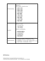
LED Definition
All Rights Reserved. Copyright 2006 Teletronics International, Inc.
2 Choke Cherry Road, Rockville, MD 20850 Tel: 301.309.8500 Fax: 301.309.8851
Item
Color
PWR
Red
RF
Yellow
LAN
Green
Received Signal Level
(5 LEDs)
Red
Status
Specification
ON
Off
Power on
** ON
Connected
OFF
Not connected
Blinking
Connected and transmitting
ON
Connected
OFF
Not connected
Blinking
Connected and transmitting
No power
** Blinking left to right Not connected (Scanning for AP)
** ON
Connected, indicating RSSI
* All ON
* AP mode.
** SU mode.
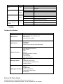
Software Specification
Item
WAN Features
LAN Features
Wireless Features
Gateway Features
Management Features
Specification
Static IP, DHCP Client, PPPoE Client
MAC Cloning
WAN Ping Inbound Filter
RIP Support
DNS Relay
DHCP Server including IP-MAC Reservation
SSID Hiding
WEP/WPA/WPA2 Enterprise
MAC Filtering
WDS
802.11d
RTS/Fragmentation Threshold
Ack Timeout
Transmit Power
Auto Channel Select
NAT
UPNP NAT Pass-through
Firewall/DMZ (Demilitarized Zone)
Quality of Service
Syslog
PingWatchdog
Firmware upgradeable
Configuration import/export
EZ-Manager
External AC Power Adapter
All Rights Reserved. Copyright 2006 Teletronics International, Inc.
2 Choke Cherry Road, Rockville, MD 20850 Tel: 301.309.8500 Fax: 301.309.8851
Item
Specification
Input Voltage
110-240VAC
Line Frequency
50/60Hz
Power Output to M/B
48VDC, 1A
Environmental
Item
Specification
Operating Temperature
-20 C to 40 C (-4 F to 104 F),
10 to 90% (non-condensing)
Storage Temperature
-25 C to 70 C (-13 F to 158 F),
10 to 90% (non-condensing)
Standards / Regulatory Compliance
•
CE, FCC
Product Kit Part Listing
1.
2.
3.
4.
5.
6.
7.
8.
TT™5800X 802.11a PCBA or TT™2400X 802.11b/g PCBA (1)
IEEE 802.11a o r IEEE 802.11b/g mini-PCI radio card (1)
Power over Ethernet Injector (1)
48VDC Power Adapter (1)
Ethernet Cable (2)
Waterproof RJ-45 Connector (1)
Mounting Hardware (1)
User Manual
Note: If any item listed above is damaged or missing, please contact your dealer immediately.
System Requirements
•
•
•
•
Any desktop or laptop with an Ethernet interface
TCP/IP protocol suite installed
Standard CAT5 Ethernet cables with RJ45 connectors
Internet Explorer 5.0 or later / Firefox 1.0 or higher
Installation
All Rights Reserved. Copyright 2006 Teletronics International, Inc.
2 Choke Cherry Road, Rockville, MD 20850 Tel: 301.309.8500 Fax: 301.309.8851
Preparation for Installation
Always double check for any missing parts from the kit you received before deployment.
Next step is to set up the computer Ethernet interface for configuring the TT™5800X/TT™2400X. you’ll need to set the
computer Ethernet interface within the same IP range as your TT™5800X/TT™2400X.
Check the following section - “Hardware Installation” and the next chapter - “Configuring Windows for IP Networking” to
obtain complete details.
Hardware Installation
Follow the procedure below to install your TT™5800X/TT™2400X device:
1.
Select a suitable place on the network to install the TT™5800X/TT™2400X. For best wireless reception and
performance the external antenna should be positioned within Line of Sight from the AP with proper alignment.
2.
Connect the TT™5800X/TT™2400X to the ODU side of the PoE Injector, via a straight Ethernet cable (Cat-5),
and then connect the NET side of the PoE Injector to either a computer or an Ethernet Switch. Note: The
TT™5800X/TT™2400X now fully supports the MDI/MDI-X standard and no longer requires the use of cross over
cable to connect directly with a computer.
3.
Connect the 48VDC power adapter to the power jack on the PoE injector to power on the
TT™5800X/TT™2400X.
4.
Check the LEDs on the TT™5800X/TT™2400X to confirm if the status is okay. At this point the Power LED
should be on in Red and Ethernet should be on in Green. The RF light should light up once the unit is associated
wirelessly with another wireless device. However at this point the unit is still in factory default setting so do not
alarm if the RF light doesn’t light up.
5.
Now the hardware installation is complete, and you may proceed to the next chapter –“Configuring Windows for
IP Networking” for instruction on setting up network configurations.
Configuring Windows for IP Networking
All Rights Reserved. Copyright 2006 Teletronics International, Inc.
2 Choke Cherry Road, Rockville, MD 20850 Tel: 301.309.8500 Fax: 301.309.8851
To establish a communication between your PCs and TT™5800X/TT™2400X, you will need to set up a static IP
address for your computer first. This section helps you configure the network settings for your operating system.
Please follow the procedures below to complete the settings (suppose the default IP address of the unit is
192.168.3.1):
Windows 98/Me
1.
Click Start on the taskbar and choose Control Panel from the submenu of Settings.
2.
Select Network to open the Network dialog box, and then under the Configuration tab, select the TCP/IP
protocol for your network card.
3.
Click Properties to open the TCP/IP Properties dialog box.
4.
Click the IP Address tab and choose Specify an IP address. For example, type in 192.168.3.x in the I P
Address (where X is any free IP number from 2-254) area and 255.255.255.0 in the Subnet Mask area. To
ensure the system is now using the IP address you specify, restart the computer.
5.
Click OK, and then restart the system.
Windows 2000
1.
Click Start on the taskbar and choose Network and Dial-up Connection from the submenu of Settings.
2.
Double-click the Local Area Connection open the Local Area Connection Properties box.
All Rights Reserved. Copyright 2006 Teletronics International, Inc.
2 Choke Cherry Road, Rockville, MD 20850 Tel: 301.309.8500 Fax: 301.309.8851
3.
Select the Internet Protocol (TCP/IP) for your network card, and then click Properties to open the Internet
Protocol (TCP/IP) Properties dialog box.
4.
Under the General tab, choose Use the following IP address, and then specify an IP address. For example,
type in 192.168.3.x in the IP Address area and 255.255.255.0 in the Subnet Mask area.
Note: Again the IP address must be in the format of 192.168.3.x. Where the value of X should be ranged from 2 to 254.
5.
Click OK.
All Rights Reserved. Copyright 2006 Teletronics International, Inc.
2 Choke Cherry Road, Rockville, MD 20850 Tel: 301.309.8500 Fax: 301.309.8851
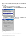
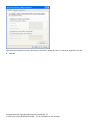
Windows XP
1. Click Start on the taskbar and choose Network from the submenu of Control Panel.
2. Right-click the Local Area Connection icon and then choose Properties from the menu. You should see the
Local Area Connection Properties dialog box shown below.
3. Select the Internet Protocol (TCP/IP) for your network card, and then click Properties.
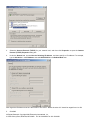
4. In the opened dialog box, choose Use the following IP address
5. Under the General tab, choose Use the following IP address, and then specify an IP address. For example, type
in 192.168.3.x in the IP Address (where X is any free IP number from 2-254) area and 255.255.255.0 in the
Subnet Mask area.
All Rights Reserved. Copyright 2006 Teletronics International, Inc.
2 Choke Cherry Road, Rockville, MD 20850 Tel: 301.309.8500 Fax: 301.309.8851
Note: Again the IP address must be in the format of 192.168.3.x. Where the value of X should be ranged from 2 to 254.
6. Click OK.
All Rights Reserved. Copyright 2006 Teletronics International, Inc.
2 Choke Cherry Road, Rockville, MD 20850 Tel: 301.309.8500 Fax: 301.309.8851
Web Configuration Interface
Note: The configuration and information pages below are based on AP mode web interface; they are also
applicable for Subscriber units as well unless they are specified.
The Default IP Addresses:
Access Point: 192.168.1.1
Subscriber:
192.168.3.1
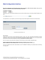
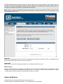
To access the web control interface please open up a browser window and type in the factory default IP address in the
URL.
Then press Enter on your keyboard, you will see the login prompt window appear similar like the one shown below:
User account:
There are 2 user accounts for web configuration interface: “Admin” and “User” with different administration privilege
respectively. "Admin" has full access to the Web-based management interface whereas "User", who will have readonly access to the Web-based management interface. No password is needed in default.
Note: You may set a new password by clicking the Tools tab after you enter the Web Configuration page
Under the main web interface page you will see the following configuration menu on the top:
BASIC, ADVANCED, TOOLS, STATUS, HELP. Check below for detail information on each section.
Once you’re logged into the web control interface of the TT™5800X/TT™2400X you’re presented with the following
home page first:
All Rights Reserved. Copyright 2006 Teletronics International, Inc.
2 Choke Cherry Road, Rockville, MD 20850 Tel: 301.309.8500 Fax: 301.309.8851
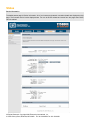
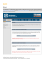
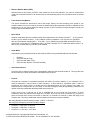
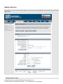
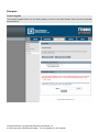
Status
Device Information
The default status page is Device Information. All of your Internet and network connection details are displayed on this
page. The firmware version is also displayed here. You can do DHCP release and renew from this page when DHCP
client is enabled.
All Rights Reserved. Copyright 2006 Teletronics International, Inc.
2 Choke Cherry Road, Rockville, MD 20850 Tel: 301.309.8500 Fax: 301.309.8851
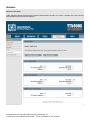
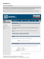
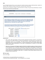
Wireless
Associated Wireless Client List
Use this option to view the wireless clients that are connected to your wireless AP gateway. You may need to
reload this page to see new changes. Click the button below to reload automatically.
The WIRELESS STATUS page on SU interface is slightly different, shows the Available AP list.
All Rights Reserved. Copyright 2006 Teletronics International, Inc.
2 Choke Cherry Road, Rockville, MD 20850 Tel: 301.309.8500 Fax: 301.309.8851
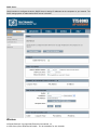
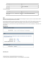
Routing
Routing Table
The routing section displays all of the routing details configured for your router.
A value of 0.0.0.0 for gateway means there is no next hop, and the IP address is directly connected to the router on
the interface specified: LAN or WAN. A value of 0.0.0.0 in both the destination IP and netmask means that this is the
default route.
All Rights Reserved. Copyright 2006 Teletronics International, Inc.
2 Choke Cherry Road, Rockville, MD 20850 Tel: 301.309.8500 Fax: 301.309.8851
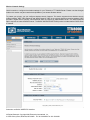
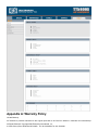
Logs
System Logs
Use this option to view the router logs. You can define what types of events you want to view and the event levels to
view. This router also has external syslog server support so you can send the log files to a computer on your network
that is running a syslog utility.
All Rights Reserved. Copyright 2006 Teletronics International, Inc.
2 Choke Cherry Road, Rockville, MD 20850 Tel: 301.309.8500 Fax: 301.309.8851
Statistics
Network Traffic Stats
Traffic Statistics displays Receive and Transmit packets passing through your router. It displays all of the LAN and
WAN packets transmit and receive statistics.
All Rights Reserved. Copyright 2006 Teletronics International, Inc.
2 Choke Cherry Road, Rockville, MD 20850 Tel: 301.309.8500 Fax: 301.309.8851
Active Sessions
The Active Sessions page displays full details of active sessions through your router. A session is a conversation
between a program or application on a LAN-side computer and a program or application on a WAN-side computer.
All Rights Reserved. Copyright 2006 Teletronics International, Inc.
2 Choke Cherry Road, Rockville, MD 20850 Tel: 301.309.8500 Fax: 301.309.8851
BASIC
Wizard
The Teletronics TT™5800X Wireless gateway provides an easy way to set up internet and wireless connections to
meet the demands of individuals who have little network knowledge and experience. There are two wizards provided:
Internet Connection Setup Wizard as well as Wireless Security Setup Wizard. Once you click any of them, you will be
guided to set it up step by step clearly.
All Rights Reserved. Copyright 2006 Teletronics International, Inc.
2 Choke Cherry Road, Rockville, MD 20850 Tel: 301.309.8500 Fax: 301.309.8851
WAN(Ethernet)
Internet Connection Settings
Use this section to configure your Internet Connection type. There are several connection types to choose from: Static
IP, DHCP, PPPoE. If you are unsure of your connection method, please contact your Internet Service Provider. The
last item interface switches among STATIC, DHCP, PPPoE according to the WAN MODE you chose.
Note: If using the PPPoE option, you will need to remove or disable any PPPoE client software on your computers.
All Rights Reserved. Copyright 2006 Teletronics International, Inc.
2 Choke Cherry Road, Rockville, MD 20850 Tel: 301.309.8500 Fax: 301.309.8851
•
DHCP client:
Host Name: Some ISP's may check your computer's Host Name. The Host Name identifies your system to the ISP's
server.
Use Unicasting: This option is normally turned off, and should remain off as long as the WAN-side DHCP server
correctly provides an IP address to the router. However, if the router cannot obtain an IP address from the DHCP
server, the DHCP server may be one that works better with unicast responses. In this case, turn the unicasting option
on, and observe whether the router can obtain an IP address. In this mode, the router accepts unicast responses from
the DHCP server instead of broadcast responses.
•
PPPoE client:
Dynamic IP: Use this option when your ISP's servers assign the router's IP address upon establishing a connection.
Static IP:
Use this option when you’re assigned a fixed IP address by your ISP.
All Rights Reserved. Copyright 2006 Teletronics International, Inc.
2 Choke Cherry Road, Rockville, MD 20850 Tel: 301.309.8500 Fax: 301.309.8851
Service Name: Some ISP's may require that you enter a Service Name.
Reconnect Mode: Typically PPPoE connections are not always on. The Teletronics router allows you to set the
reconnection mode as: Always on, On demand and Manual.
LAN(Wireless)
Network Settings
These are the settings of the LAN (Local Area Network) interface for the router. The router's local network (LAN)
settings are configured based on the IP Address and Subnet Mask assigned in this section. The IP address is also
used to access this Web-based management interface.
DHCP
All Rights Reserved. Copyright 2006 Teletronics International, Inc.
2 Choke Cherry Road, Rockville, MD 20850 Tel: 301.309.8500 Fax: 301.309.8851
DHCP Server
Use this section to configure the built-in DHCP Server to assign IP addresses to the computers on your network. The
DHCP settings portion is hidden before DHCP server is checked.
Wireless
All Rights Reserved. Copyright 2006 Teletronics International, Inc.
2 Choke Cherry Road, Rockville, MD 20850 Tel: 301.309.8500 Fax: 301.309.8851
Wireless Network Settings
Use this section to configure the wireless settings for your Teletronics TT™5800X Router. Please note that changes
made on this section may also need to be duplicated on your remote Wireless devices.
To protect your privacy you can configure wireless security features. This device supports three wireless security
modes including: WEP, WPA-Personal, and WPA-Enterprise. WEP is the original wireless encryption standard. WPA
provides a higher level of security. WPA-Personal does not require an authentication server. The WPA-Enterprise
option requires an external RADIUS server. The BASIC WIRELESS SETTINGS portion is hidden before DHCP server
is checked.
Subscriber unit BASIC WIRELESS interface:
All Rights Reserved. Copyright 2006 Teletronics International, Inc.
2 Choke Cherry Road, Rockville, MD 20850 Tel: 301.309.8500 Fax: 301.309.8851
BASIC WIRELESS SETTINGS
•
Wireless Mode
Infrastructure: An 802.11 networking framework in which devices communicate with each other by first going
through an Access Point (AP).
Ad-hoc: An 802.11 networking framework in which devices or stations communicate directly with each other,
without the use of an access point (AP). Use this mode if there is no wireless infrastructure or where services
are not required.
All Rights Reserved. Copyright 2006 Teletronics International, Inc.
2 Choke Cherry Road, Rockville, MD 20850 Tel: 301.309.8500 Fax: 301.309.8851
•
Wireless Network Name (SSID)
Network Name is also known as SSID, which stands for Service Set Identifier. Any client in Infrastructure
mode has to indicate the SSID of an Access Point to start accessing the service from behind such as internet
access.
•
Transmission rate (Mbits/s)
This option indicates the transmission rate of the bridge. Specify the rate according to the speed of your
wireless network from the list. Most of the time the default setting Best (automatic) should be selected for best
performance. You may want to adjust the setting manually If your link quality and signal strength is usually low
or high to get the best performance.
•
802.11 Mode
Wireless mode allows the user to select whether this wireless device will connect to an 802.1 1b only network,
an 802.1 1g only network, an 802.1 1a only network or both b/g networks. If you only have b or g wireless
devices on the network selecting 802.1 1b or 802.1 1g only network will provide better performance then in
mixed mode. In the case of TT™5800X only 802.1 1a mode is allowed. For TT™2400X the options of 802.1 1b,
802.11g only or Mixed 802.11g and 802.11b is available.
•
Super Mode
Super Mode is only supported if both the client and the AP are using compatible Atheros radio chipsets
•
•
•
•
•
Disabled
Super A/G without Turbo
Super A/G with Static Turbo
Super A/G with Dynamic Turbo (AR enabled)
Auto Channel Select
Check this box to enable Access Point to automatically select the best channel at start up. This may take upto
20 seconds and no clients will be able to associate during this period.
•
Channel
Channels are important to understand because they affect the overall capacity of your Wireless LAN. A
channel represents a narrow band of radio frequency. A radio frequency modulates within a band of
frequencies; as a result, there is a limited amount of bandwidth within any given range to carry data. It is
important that the frequencies do not overlap or else the throughput would be significantly lowered as the
network sorts and reassembles the data packets sent over the air.
These are the only 3 channels out of the 11 available that do not overlap with one another. To avoid
interference within the network with multiple APs, set each AP to use one of the 3 channels (e.g. Channel 1)
and then the other AP to be one of the other 2 channels (i.e. Channel 6 or Channel 11) within the range of the
wireless radio. This simple method will reduce interference and improve network reliability.
802.11b/g Wireless Channel Frequency Range: 2.4 GHz – 2.497 GHz
802.11b/g Non-overlapping Channel Frequency Ranges
•
•
•
Channel 1 = 2.401 GHz – 2.423 GHz
Channel 6 = 2.426 GHz – 2.448 GHz
Channel 11 = 2.451 GHz – 2.473 GHz
All Rights Reserved. Copyright 2006 Teletronics International, Inc.
2 Choke Cherry Road, Rockville, MD 20850 Tel: 301.309.8500 Fax: 301.309.8851
Americas: Wireless Channels 1 – 11
Asia: Wireless Channels 1 – 14
Europe: Wireless Channels 1 – 13
802.11a Wireless Channel Frequency Range: 5.15 GHz – 5.35 GHz, 5.725 – 5.825
802.11a is an extension to 802.11 that applies to wireless LANs and provides up to 54 Mbps in the 5GHz band.
802.11a uses an orthogonal frequency division multiplexing encoding scheme rather than FHSS or DSSS. Unlike that
of 802.11b/g, 802.11a standard separate its channels into 3 100MHz segments in the US.
The lower and middle band, accommodate 8 channels in a total bandwidth of 200 MHz and the upper band
accommodates 4 channels in a 100 MHz bandwidth. The frequency channel center frequencies are spaced 20 MHz
apart. The outermost channels of the lower and middle bands are centered 30 MHz from the outer edges. In the upper
band the outermost channel centers are 20 MHz from the outer edges.
In addition to the frequency and channel allocations, transmit power is a key parameter regulated in the 5 GHz U-NII
band. Three transmit power levels are specified: 40 mW, 200 mW and 800 mW. The upper band defines RF transmit
power levels suitable for bridging applications while the lower band specifies a transmit power level suitable for shortrange indoor home and small office environments.
802.11a Non-overlapping Channel Frequency Ranges
Lower Band (5.15 - 5.25 GHz ) – Maximum Output Power 40mW
•
•
•
•
Channel 36 = 5.15 – 5.18
Channel 40 = 5.18 – 5.20
Channel 44 = 5.20 – 5.22
Channel 48 = 5.22 – 5.25
Middle Band (5.25 - 5.35 GHz ) – Maximum Output Power 200mW
•
•
•
•
Channel 52 = 5.25 – 5.28
Channel 56 = 5.28 – 5.30
Channel 60 = 5.30 – 5.32
Channel 64 = 5.32 – 5.35
Upper Band (5.725 - 5.825 GHz) – Maximum Output Power 200mW
•
•
•
•
•
Channel 149 = 5.725 – 5.745
Channel 153 = 5.745 – 5.765
Channel 157 = 5.765 – 5.785
Channel 161 = 5.785 – 5.805
Channel 165 = 5.805 – 5.825
Special Atheros Turbo Mode Channels
*Use this setting only when both side of the wireless connection is using the Atheros chipset. The radio will combine 2
free channels for the wireless transmission to double the bandwidth.
•
•
•
•
•
Channel 42 = 5.210
Channel 50 = 5.250
Channel 58 = 5.290
Channel 152 = 5.760
Channel 160 = 5.800
Wireless Security Mode
There are 3 Wireless Security Mode you can choose: WEP, WPA-Personal and WPA-Enterprise.
All Rights Reserved. Copyright 2006 Teletronics International, Inc.
2 Choke Cherry Road, Rockville, MD 20850 Tel: 301.309.8500 Fax: 301.309.8851
WEP
Short for Wired Equivalent Privacy, a security protocol for wireless local area networks (WLANs) defined in the 802.11b
standard. WEP is designed to provide the same level of security as that of a wired LAN.
Select the key to be used as the default key. Data transmissions are always encrypted using the default key. The other
keys can only be used to decrypt received data.
Authentication
•
Open - Open system authentication involves a two-step authentication transaction sequence. The first step in
the sequence is the identity assertion and request for authentication. The second step in the sequence is the
authentication result. If it is “successful”, the station shall be mutually authenticated. Open system
authentication does not provide authentication. It provides identification using the wireless adapter's MAC
address. Open system authentication is used when no authentication is required. It is the default
authentication algorithm.
•
Shared Key - Shared key authentication supports authentication of stations as either a member of those who
know a shared secret key or a member of those who do not. Shared key authentication is not secure and is
not recommended for use. It verifies that an authentication-initiating station has knowledge of a shared secret.
This is similar to pre-shared key authentication for Internet Protocol security (IPSec). The 802.11 standard
currently assumes that the shared secret is delivered to the participating wireless clients by means of a more
secure channel that is independent of IEEE 802.11. In practice, a user manually types this secret for the
wireless AP and the wireless client.
WEP key lengths
64 bit (10 Hex Digit)
All Rights Reserved. Copyright 2006 Teletronics International, Inc.
2 Choke Cherry Road, Rockville, MD 20850 Tel: 301.309.8500 Fax: 301.309.8851
WEP Key type
Example
64-bit WEP with 5 characters
Key1= 2e3f4
64-bit WEP with 10 hexadecimal digits
Key1= 123456789A
('0-9', 'A-F')
128 bit (26 Hex Digit)
WEP Key type
Example
128-bit WEP with 13 characters
Key1= 2e3f4w345ytre
128-bit WEP with 26 hexadecimal digits
Key1= 112233445566778899AABBCDEF
('0-9', 'A-F')
WPA
Short for Wi-Fi Protected Access, a Wi-Fi standard that was designed to improve upon the security features of WEP.
WPA has the following improvements over the WEP.
Improved data encryption through the temporal key integrity protocol (TKIP) or AES. TKIP scrambles the keys using a
hashing algorithm and, by adding an integrity-checking feature, ensures that the keys haven’t been tampered with.
*Remember that any client that does not support the WPA standard will not be able to handshake / authenticate with
WPA enabled.
WPA-Personal
WPA-Enterprise
All Rights Reserved. Copyright 2006 Teletronics International, Inc.
2 Choke Cherry Road, Rockville, MD 20850 Tel: 301.309.8500 Fax: 301.309.8851
WPA Mode
•
WPA
o
WPA addresses all known vulnerabilities in WEP, the original, less secure 40 or 104-bit encryption
scheme in the IEEE 802.11 standard. WPA also provides user authentication, since WEP lacks any
means of authentication. Designed to secure present and future versions of IEEE 802.11 devices,
WPA is a subset of the IEEE 802.11i specification. WPA replaces WEP with a strong new encryption
technology called Temporal Key Integrity Protocol (TKIP) with Message Integrity Check (MIC). It also
provides a scheme of mutual authentication using either IEEE 802.1X/Extensible Authentication
Protocol (EAP) authentication or pre-shared key (PSK) technology. WPA was designed and has been
scrutinized by well-known cryptographers. It can be implemented immediately and inexpensively as a
software or firmware upgrade to most existing Wi-Fi CERTIFIED™ access points and client devices
All Rights Reserved. Copyright 2006 Teletronics International, Inc.
2 Choke Cherry Road, Rockville, MD 20850 Tel: 301.309.8500 Fax: 301.309.8851
with minimal degradation in network performance. WPA offers standards-based, Wi-Fi CERTIFIED
security. It assures users that the Wi-Fi CERTIFIED devices they buy will be cross-vendor compatible.
When properly installed, WPA provides a high level of assurance to enterprises, small businesses and
home users that data will remain protected and that only authorized users may access their networks.
For enterprises that have already deployed IEEE 802.1X authentication, WPA offers the advantage of
leveraging existing authentication databases and infrastructure.
•
WPA2
o WPA2 is the second generation of WPA security; providing enterprise and consumer Wi-Fi® users with
a high level of assurance that only authorized users can access their wireless networks. Launched in
September 2004 by the Wi-Fi Alliance, WPA2 is the certified interoperable version of the full IEEE
802.11i specification which was ratified in June 2004. Like WPA, WPA2 supports IEEE 802.1X/EAP
authentication or PSK technology. It also includes a new advanced encryption mechanism using the
Counter-Mode/CBC-MAC Protocol (CCMP) called the Advanced Encryption Standard (AES). AES
satisfies U.S. government security requirements. It has been adopted as an official government
standard by the U.S. Department of Commerce and the National Institute of Standards and
Technology (NIST). Organizations that require the AES encryption available in WPA2 should be aware
that upgrading to it may require new hardware. Section II of this document offers a roadmap for
organizations planning to upgrade to WPA2. Considerations for its deployment are outlined in Section
III.
Cipher Type
•
TKIP
o
•
AES
o
•
TKIP and AES
o If clients support both the TKIP and AES standards then this would be the strongest cipher type to
use. That combines both the TKIP and AES security.
Temporal Key Integrity Protocol is an upgrade to the WEP known as WEP 1.1 that fixes known
security problems in WEP’s implementation of the RC4 stream cipher. TKIP scrambles the keys using
a hashing algorithm and, by adding an integrity-checking feature, ensures that the keys haven’t been
tampered with.
Advanced Encryption Standard (Rijndael Cypher) is the U.S. government's next-generation
cryptography algorithm, which will replace DES and 3DES. AES works at multiple network layers
simultaneously. Supports 128, 192 and 256 bit keys. AES and 802.11i (WEP version 2) is based on
32bit processing unlink the older standard.
EAP (802.1x)
When WPA enterprise is enabled, the router uses EAP (802.1x) to authenticate clients via a remote RADIUS server.
PSK
PSK stands for Pre-Shared-Key and serves as a password. User may key in an 8 to 63 characters string to set the
password or leave it blank, in which the 802.1x Authentication will be activated. Note that if user key in own password,
make sure to use the same password on client's end.
ADVANCED
All Rights Reserved. Copyright 2006 Teletronics International, Inc.
2 Choke Cherry Road, Rockville, MD 20850 Tel: 301.309.8500 Fax: 301.309.8851
Quality of Service
The Quality of Service feature helps improve your network special application performance by prioritizing
applications.
Quality of Service setup
All Rights Reserved. Copyright 2006 Teletronics International, Inc.
2 Choke Cherry Road, Rockville, MD 20850 Tel: 301.309.8500 Fax: 301.309.8851
Enable Quality of Service
This option is disabled by default. Enable it for better performance and experience with interactive applications,
such as VoIP.
Automatic Classification
This option is enabled by default so that your router will automatically determine which programs should have
network priority.
Dynamic Fragmentation
This option should be enabled when you have a slow Internet uplink. It helps to reduce the impact that large low
priority network packets can have on more urgent ones by breaking the large packets into several smaller packets.
Automatic Uplink Speed
When enabled, this option causes the router to automatically measure the useful uplink bandwidth each time the
WAN interface is re-established (after a reboot, for example).
Measured Uplink Speed
This is the uplink speed measured when the WAN interface was last re-established. The value may be lower than
that reported by your ISP as it does not include all of the network protocol overheads associated with your ISP's
network. Typically, this figure will be between 87% and 91% of the stated uplink speed for xDSL connections and
around 5 kbps lower for cable network connections.
Uplink Speed
If Automatic Uplink Speed is disabled, this options allows you to set the uplink speed manually. Uplink speed is the
speed at which data can be transferred from the router to your ISP. This is determined by your ISP. ISPs often
specify speed as a downlink/uplink pair; for example, 1.5Mbits/284Kbits. For this example, you would enter "284".
Alternatively you can test your uplink speed with a service such as www.dslreports.com. Note however that sites
such as DSL Reports, because they do not consider as many network protocol overheads, will generally note
speeds slightly lower than the Measured Uplink Speed or the ISP rated speed.
Connection Type
By default, the router automatically determines whether the underlying connection is an xDSL/Frame-relay network
or some other connection type (such as cable modem or Ethernet), and it displays the result as Detected xDSL or
Frame Relay Network. If you have an unusual network connection in which you are actually connected via xDSL
but for which you configure either "Static" or "DHCP" in the WAN settings, setting this option to xDSL or Other
Frame Relay Network ensures that the router will recognize that it needs to shape traffic slightly differently in
order to give the best performance. Choosing xDSL or Other Frame Relay Network causes the measured uplink
speed to be reported slightly lower than before on such connections, but gives much better results.
Detected xDSL or Frame Relay Network
When Connection Type is set to Auto-detect, the automatically detected connection type is displayed here.
Add/Edit Quality of Service Rule
Automatic classification will be adequate for most applications, and specific Quality of Service Rules will not be
required. A Quality of Service Rule identifies a specific message flow and assigns a priority to that flow.
Enable
Each entry in Quality of Service Rules List can be active (enabled) or inactive (disabled)
Name
Create a name for the rule that is meaningful to you.
Priority
The priority of the message flow is entered here. 0 receives the highest priority (most urgent) and 255 receives the
lowest priority (least urgent).
Protocol
The protocol used by the messages.
Source IP Range
The rule applies to a flow of messages whose LAN-side IP address falls within the range set here.
Source Port Range
The rule applies to a flow of messages whose LAN-side port number is within the range set here.
Destination IP Range
All Rights Reserved. Copyright 2006 Teletronics International, Inc.
2 Choke Cherry Road, Rockville, MD 20850 Tel: 301.309.8500 Fax: 301.309.8851
The rule applies to a flow of messages whose WAN-side IP address falls within the range set here.
Destination Port Range
The rule applies to a flow of messages whose WAN-side port number is within the range set here.
Save
Saves the new or edited Quality of Service Rule in the following list. When finished updating the Quality of Service
rules, you must still click the Save Settings button at the top of the page to make the changes ef
fective and
permanent.
Quality of Service Rules List
The section shows the currently defined Quality of Service rules. A Quality of Service rule can be changed by
clicking the Edit icon, or deleted by clicking the Delete icon. When you click the Edit icon, the item is highlighted,
and the "Edit Quality of Service Rule" section is activated for editing.
Routing
All Rights Reserved. Copyright 2006 Teletronics International, Inc.
2 Choke Cherry Road, Rockville, MD 20850 Tel: 301.309.8500 Fax: 301.309.8851
The Routing option allows you to define fixed routes to defined destinations. Adds a new route to the IP routing table or
edits an existing route in Add Route field.
The Routes List section shows the current routing table entries. Certain required routes (grayed out items) are
predefined and cannot be changed. Routes that you added can be changed by clicking the Edit icon, or deleted by
clicking the Delete icon. When you click the Edit icon, the item is highlighted, and the "Edit Route" section is activated
for editing.
MAC Address Filtering
All Rights Reserved. Copyright 2006 Teletronics International, Inc.
2 Choke Cherry Road, Rockville, MD 20850 Tel: 301.309.8500 Fax: 301.309.8851
The MAC (Media Access Controller) Address filter option is used to control network access based on the MAC
Address of the network adapter. A MAC address is a unique ID assigned by the manufacturer of the network adapter.
This feature can be configured to ALLOW or DENY network/Internet access.
Firewall
All Rights Reserved. Copyright 2006 Teletronics International, Inc.
2 Choke Cherry Road, Rockville, MD 20850 Tel: 301.309.8500 Fax: 301.309.8851
The DMZ (Demilitarized Zone) option provides you with an option to set a single computer on your network outside of
the router. If you have a computer that cannot run Internet applications successfully from behind the router, then you
can place the computer into the DMZ for unrestricted Internet access.
Note: Putting a computer in the DMZ may expose that computer to a variety of security risks. Use of this option is only
recommended as a last resort.
Enable SPI
Enable SPI (stateful packet inspection) to prevent cyberattacks by tracking more state per session. It validates that the
traffic passing through that session conforms to the protocol.
Enable DMZ
DMZ Provides an option to set a single computer on your network outside of the router.
DMZ IP Address
Specify the IP address of the computer on the LAN that you want to have unrestricted Internet communication. If this
computer obtains its address Automatically using DHCP, then you may want to make a static reservation on the Basic
-> DHCP page so that the IP address of the DMZ machine does not change.
Advanced Wireless
All Rights Reserved. Copyright 2006 Teletronics International, Inc.
2 Choke Cherry Road, Rockville, MD 20850 Tel: 301.309.8500 Fax: 301.309.8851
If you are not familiar with these Advanced Wireless settings, please read the help section before attempting to modify
these settings.
Fragmentation threshold
Fragmentation Threshold is the maximum length of the frame, beyond which payload must be broken up (fragmented)
into two or more frames. Collisions occur more often for long frames because sending them occupies the channel for a
longer period of time, increasing the chance that another station will transmit and cause collision. Reducing
Fragmentation Threshold results in shorter frames that "busy" the channel for shorter periods, reducing packet error
rate and resulting retransmissions. However, shorter frames also increase overhead, degrading maximum possible
throughput, so adjusting this parameter means striking a good balance between error rate and throughput.
RTS threshold
RTS Threshold is the frame size above which an RTS/CTS handshake will be performed before attempting to transmit.
RTS/CTS ask for permission to transmit to reduce collisions, but adds considerable overhead. Disabling RTS/CTS can
reduce overhead and latency in WLANs where all stations are close together, but can increase collisions and degrade
performance in WLANs where stations are far apart and unable to sense each other to avoid collisions (aka Hidden
Nodes). If you are experiencing excessive collisions, you can try turning RTS/CTS on or (if already on) reduce
All Rights Reserved. Copyright 2006 Teletronics International, Inc.
2 Choke Cherry Road, Rockville, MD 20850 Tel: 301.309.8500 Fax: 301.309.8851
RTS/CTS Threshold on the affected stations.
Beacon Period
In wireless networking, a beacon is a packet sent by a connected device to inform other devices of its presence and
readiness. When a wirelessly networked device sends a beacon, it includes with it a beacon interval, which specifies
the period of time before it will send the beacon again. The interval tells receiving devices on the network how long
they can wait in low-power mode before waking up to handle the beacon. Network managers can adjust the beacon
interval, usually measured in milliseconds (ms) or its equivalent, kilo microseconds (Kmsec).
802.11d Enable
802.11d is a wireless network communications specification for use in countries where systems using other standards
in the 802.11 family are not allowed to operate. The 802.11d specification is well suited for systems that want to
provide global Roaming.
ACK Timeout
When a packet is sent out from 802.11 Station A it will then wait for an 'ACKnowledgement frame' from 802.11 Station
B. Station A will only wait for a certain amount of time (ACK timeout) or ACK window. If the ACK is NOT received within
that timeout period then the packet will be re-transmitted from Station A resulting in reduced throughput. When sending
LOTS of packets as in 802.11g and 802.11a the constant re-transmission could cost severe performance degradation
due to the ACK frame not making it back to 802.11 Station A in time. This will have a dramatic impact on the
throughput of the link regardless of the quantity of signal strength and good receiver sensitivity.
Transmit Power
This section controls the power output for the mini-PCI radio card. The valid input range for this section is in the range
of 0-23 in dBm units. The default value is 23 dBm or 200mW.
Enable WDS
The Wireless Distribution System (Repeater) functionality enables this AP to support wireless traffic to other WDS
relay Access Points. In other words it is like bridging between the 2 access points in order to extend the reach of the
wireless network beyond that of a single AP can cover. By enabling the WDS feature the distance of wireless
networking is thus extended for authenticated client devices that can roam from this Access Point to another.
WDS can extend the reach of your network into areas where cabling might be too difficult.
The TT™5800X/TT™2400X in Access Point mode can support up to 6 other Access Points for WDS communication.
Enter the MAC Address of other Access Points in the area that you want to add to the WDS. The MAC Address of this
Access Point should be also added in other member WDS Access Points so that they can communicate.
TOOLS
All Rights Reserved. Copyright 2006 Teletronics International, Inc.
2 Choke Cherry Road, Rockville, MD 20850 Tel: 301.309.8500 Fax: 301.309.8851
Admin
Administrator Settings
The Admin option is used to set a password for access to the Web-based management. By default there is no
password configured. It is highly recommended that you create a password to keep your new router secure.
All Rights Reserved. Copyright 2006 Teletronics International, Inc.
2 Choke Cherry Road, Rockville, MD 20850 Tel: 301.309.8500 Fax: 301.309.8851
Enable Remote Management
Enabling Remote Management allows you to manage the router from anywhere on the Internet. Disabling Remote
Management allows you to manage the router only from computers on your LAN.
Remote Admin Port
The port that you will use to address the management interface from the Internet. For example, if you specify port 1080
here, then, to access the router from the Internet, you would use a URL of the form: http://my.domain.com:1080/.
Remote Admin Inbound Filter
Select a filter that controls access as needed for this admin port. If you do not see the filter you need in the list of
filters, go to the Advanced -> Inbound Filter screen and create a new filter.
Admin Idle Timeout
The amount of time before the administration session (either remote or local) is closed when there is no activity.
Save Configuration
This option allows you to save the router's configuration to a file on your computer. Be sure to save the configuration
before performing a firmware upgrade.
Restore Configuration from File
Use this option to load previously saved router configuration settings.
ENABLE UPnP:
Once enabled, UPnP traffic can pass through.
REGISTER
The TT™5800X/TT™2400X has implemented a hardware modification authorization process to prevent fraudulent
hardware from other manufacturers. This will require any hardware change on the radio card used on the
TT™5800X/TT™2400X to input a serial code generated based on each unique MAC address. Please contact
Teletronics Support to a pickup a valid serial number to deactivate the pre-registration protection after a radio card
swap. If no valid serial code has been input into the unit, features such as SSID and Wireless Channel will be locked
All Rights Reserved. Copyright 2006 Teletronics International, Inc.
2 Choke Cherry Road, Rockville, MD 20850 Tel: 301.309.8500 Fax: 301.309.8851
up.
SysLog
The SysLog options allow you to send log information to a SysLog Server.
Enable Logging to Syslog Server
Enable this option if you have a syslog server currently running on the LAN and wish to send log messages to it.
Enabling this option causes the following parameter to be displayed.
Syslog Server IP Address
Enter the LAN IP address of the Syslog Server.
All Rights Reserved. Copyright 2006 Teletronics International, Inc.
2 Choke Cherry Road, Rockville, MD 20850 Tel: 301.309.8500 Fax: 301.309.8851
Ping Watchdog
The Ping Watchdog option is useful for having the stable wireless connection.
Enable Ping Watchdog
Enable this option if you want to use the ping watchdog utility. Ping watchdog utility keep tracing the TCP/IP link
between the device and device of destination. Usually, the destination IP address is from the other end of wireless
connection, such as the AP(SU) IP address for a SU(AP). Enabling this option causes the following parameter to be
displayed.
Ping Watchdog destination IP Address
Enter the destination IP address of ping watchdog utility.
All Rights Reserved. Copyright 2006 Teletronics International, Inc.
2 Choke Cherry Road, Rockville, MD 20850 Tel: 301.309.8500 Fax: 301.309.8851
System
System Settings
The System Settings section allows you to reboot the device, or restore the router to the factory default settings.
Restoring the unit to the factory default settings will erase all settings, including any rules that you have created.
All Rights Reserved. Copyright 2006 Teletronics International, Inc.
2 Choke Cherry Road, Rockville, MD 20850 Tel: 301.309.8500 Fax: 301.309.8851
Firmware
Firmware Upgrade
The Firmware Upgrade section can be used to update your router to the latest firmware code to improve functionality
and performance.
All Rights Reserved. Copyright 2006 Teletronics International, Inc.
2 Choke Cherry Road, Rockville, MD 20850 Tel: 301.309.8500 Fax: 301.309.8851
Help Menu
The Help Menu provides a comprehensive help of all web interface items as well as a glossary. You can find the
helped item from its tree structure easily.
All Rights Reserved. Copyright 2006 Teletronics International, Inc.
2 Choke Cherry Road, Rockville, MD 20850 Tel: 301.309.8500 Fax: 301.309.8851
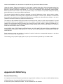
Appendix A: Warranty Policy
Limited Warranty
All Teletronics’ products warranted to the original purchaser to be free from defects in materials and workmanship
All Rights Reserved. Copyright 2006 Teletronics International, Inc.
2 Choke Cherry Road, Rockville, MD 20850 Tel: 301.309.8500 Fax: 301.309.8851
under normal installation, use, and service for a period of one (1) year from the date of purchase.
Under this warranty, Teletronics International, Inc. shall repair or replace (at its option), during the warranty period, any
part that proves to be defective in material of workmanship under normal installation, use and service, provided the
product is returned to Teletronics International, Inc., or to one of its distributors with transportation charges prepaid.
Returned products must include a copy of the purchase receipt. In the absence of a purchase receipt, the warranty
period shall be one (1) year from the date of manufacture.
This warranty shall be voided if the product is damaged as a result of defacement, misuse, abuse, neglect, accident,
destruction or alteration of the serial number, improper electrical voltages or currents, repair, alteration or maintenance
by any person or party other than a Teletronics International, Inc. employee or authorized service facility, or any use in
violation of instructions furnished by Teletronics International, Inc.
This warranty is also rendered invalid if this product is removed from the country in which it was purchased, if it is used
in a country in which it is not registered for use, or if it is used in a country for which it was not designed. Due to
variations in communications laws, this product may be illegal for use in some countries. Teletronics International, Inc.
assumes no responsibility for damages or penalties incurred resulting from the use of this product in a manner or
location other than that for which it is intended.
IN NO EVENT SHALL TELETRONICS INTERNATIONAL, INC. BE LIABLE FOR ANY SPECIAL, INCIDENTAL OR
CONSEQUENTIAL DAMAGES FOR BREACH OF THIS OR ANY OTHER WARRANTY, EXPRESSED OR IMPLIED,
WHATSOEVER.
Some states do not allow the exclusion or limitation of special, incidental or consequential damages, so the above
exclusion or limitation may not apply to you.
This warranty gives you specific legal rights, and you may also have other rights that vary from state to state.
Appendix B: RMA Policy
Product Return Policy
It is important to us that all Teletronics’ products are bought with full confidence. If you are not 100% satisfied with any
All Rights Reserved. Copyright 2006 Teletronics International, Inc.
2 Choke Cherry Road, Rockville, MD 20850 Tel: 301.309.8500 Fax: 301.309.8851
product purchased from Teletronics you may receive a prompt replacement or refund, subject to the terms and
conditions outlined below.
IMPORTANT: Before returning any item for credit or under warranty repair, you must obtain a Return Merchandise
Authorization (RMA) number by filling out the RMA form. Products will not be accepted without an RMA number. All
products being shipped to Teletronics for repair / refund / exchange must be freight prepaid (customer pays for
shipping). For all under warranty repair/replacement, Teletronics standard warranty applies.
30-Day full refund or credit policy:
1. Product was purchased from Teletronics no more than 30 day prior to the return request.
2. All shipping charges associated with returned items are non-refundable.
3. Products are returned in their original condition along with any associated packaging, accessories, mounting
hardware and manuals. Any discrepancy could result in a delay or partial forfeiture of your credit.
Unfortunately Teletronics cannot issue credits for:
1. Products not purchased from Teletronics directly. If you purchased from a reseller or distributor you must contact
them directly for return instructions.
2. Damaged items as a result of misuse, neglect, or improper environmental conditions.
3. Products purchased direct from Teletronics more than 30 days prior to a product return request.
To return any product under 1 year warranty for repair/replacement, follow the RMA procedure.
Appendix C: Regulatory Information
Statement of Conditions
All Rights Reserved. Copyright 2006 Teletronics International, Inc.
2 Choke Cherry Road, Rockville, MD 20850 Tel: 301.309.8500 Fax: 301.309.8851
We may make improvements or changes in the product described in this documentation at any time. The information
regarding to the product in this manual are subject to change without notice.
We assume no responsibility for errors contained herein or for direct, indirect, special, incidental, or consequential
damages with the furnishing, performance, or use of this manual or equipment supplied with it, even if the suppliers
have been advised of the possibility of such damages.
Electronic Emission Notices
This device complies with Part 15 of the FCC Rules. Operation is subject to the following two conditions:
(1) This device may not cause harmful interference.
(2) This device must accept any interference received, including interference that may cause undesired operation.
FCC Information
The Federal Communication Commission Radio Frequency Interference Statement includes the following paragraph:
The equipment has been tested and found to comply with the limits for a Class B Digital Device, pursuant to part 15 of
the FCC Rules. These limits are designed to provide reasonable protection against harmful interference in a residential
installation. This equipment generates, uses and can radiate radio frequency energy and, if not installed and used in
accordance with the instruction, may cause harmful interference to radio communication. However, there is no
guarantee that interference will not occur in a particular installation. If this equipment does cause harmful interference
to radio or television reception, which can be determined by turning the equipment off and on, the user is encouraged
to try to overcome the interference by one or more of the following measures:
-
Reorient or relocate the receiving antenna.
Increase the separation between the equipment and receiver.
Connect the equipment into an outlet on a circuit different from that to which the receiver is connected.
Consult the dealer or an experienced radio/TV technician for help.
The equipment is for home or office use.
Important Note
FCC RF Radiation Exposure Statement: This equipment complies with FCC RF radiation exposure limits set forth for
an uncontrolled environment. This equipment should be installed and operated with a minimum distance of 20cm
between the antenna and your body and must not be co-located or operating in conjunction with any other antenna or
transmitter.
Caution: Changes or modifications not expressly approved by the party responsible for compliance could void the
user's authority to operate the equipment.
R&TTE Compliance Statement
This equipment complies with all the requirements of the Directive 1999/5/EC of the European Parliament and the
Council of 9 March 1999 on radio equipment and telecommunication terminal equipment (R&TTE)and the mutual
recognition of their conformity. The R&TTE Directive repeals and replaces in the directive 98/13/EEC. As of April 8,
2000.
European Union CE Marking and Compliance Notices
Products intended for sale within the European Union are marked, which indicates compliance with the applicable
directives identified below. This equipment also carries the Class 2 identifier.
With the Conformité Européene (CE) and European standards and amendments, we declare that the equipment
described in this document is in conformance with the essential requirements of the European Council Directives,
standards, and other normative documents listed below:
73/23/EEC Safety of the User (article 3.1.a)
89/336/EEC Electromagnetic Compatibility (article 3.1.b)
All Rights Reserved. Copyright 2006 Teletronics International, Inc.
2 Choke Cherry Road, Rockville, MD 20850 Tel: 301.309.8500 Fax: 301.309.8851
1999/5/EC (R&TTE) Radio and Telecommunications Terminal Equipment Directive.
EN 60950 2000 Safety of Information Technology Equipment, Including Electrical Business Equipment.
EN 300 328 V1.4.1(2003) Electromagnetic compatibility and Radio spectrum Matters (ERM); Wideband Transmission
systems; Data transmission equipment operating in the 2,4 GHz ISM band and using spread spectrum modulation
techniques; Harmonized EN covering essential requirements under article 3.2 of the R&TTE Directive.
EN 301 489-1, V1.4.1(2002); EN 301 489-17, V1.2.1(2002) – Electromagnetic compatibility and radio spectrum
matters (ERM); electromagnetic compatibility (EMC) standard for radio equipment and services: Part 1: Common
technical requirements; Part 17: Part 17: Specific conditions for 2,4 GHz wideband transmission systems and5 GHz
high performance RLAN equipment
Warning: According to ERC/REC 70-30 appendix 3 National Restrictions, annex 3 Band A “RLANs and HIPERLANs.”
See list of 802.11b/g restrictions for specific countries under the heading “European Economic Area Restrictions” as
below.
English
This product follows the provisions of the European Directive 1999/5/EC.
Danish
Dette produkt er i overensstemmelse med det europæiske direktiv 1999/5/EF
Dutch
Dit product is in navolging van de bepalingen van Europees Directief 1999/5/EC.
Finnish
Tämä tuote noudattaa EU-direktiivin 1999/5/EY määräyksiä.
French
Ce produit est conforme aux exigences de la Directive Européenne 1999/5/CE.
Appendix D: Contact Information
Need to contact Teletronics?
Visit us online for information on the latest products and updates to your existing products at:
All Rights Reserved. Copyright 2006 Teletronics International, Inc.
2 Choke Cherry Road, Rockville, MD 20850 Tel: 301.309.8500 Fax: 301.309.8851
http://www.teletronics.com
Can't find information about a product you want to buy on the web? Do you want to know more about networking with
Teletronics products?
Give us a call at: 301-309-8500 Or fax your request in to: 301-309-8551
Don't wish to call? You can e-mail us at: [email protected]
If any Teletronics product proves defective during its warranty period, you can email the Teletronics Return
Merchandise Authorization department to obtain a Return Authorization Number at: [email protected]
(Details on Warranty and RMA issues can be found in Appendix A and B)
Appendix E: WDS Explained
One of the requirement for a WDS network is that the operational frequency channel on all the APs must be the same.
This is one of the reasons why there is a huge bandwidth penalty when setting up a wireless network in WDS mode.
How to properly configure your APs in a WDS network will foremost depend on the locations of your wireless hotspots.
All Rights Reserved. Copyright 2006 Teletronics International, Inc.
2 Choke Cherry Road, Rockville, MD 20850 Tel: 301.309.8500 Fax: 301.309.8851
Please take a look at the following two WDS topology examples:
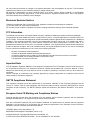
WDS in a Star Configuration:
This is the mode to use if you’re expanding the hotspots in the area around your master AP that is connected to the
WAN. What you’ll need to do is enable WDS and ACL on all the APs. Then input each of the MAC addresses of Slave
A,B,C into the Master AP under both the WDS and ACL section. For the Slave APs A,B,C you’ll input only the MAC
address of the Master AP into the WDS and ACL list to limit them to direct their traffic through the Master AP only.
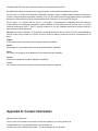
WDS in Chain Configuration:
All Rights Reserved. Copyright 2006 Teletronics International, Inc.
2 Choke Cherry Road, Rockville, MD 20850 Tel: 301.309.8500 Fax: 301.309.8851
In this configuration setup example you’ll be expanding your wireless network coverage that will span an area in
length.
•
AP A will have only AP B’s MAC address in its WDS and ACL configuration setting.
•
AP B will have AP A and C’s MAC address in its WDS and ACL configuration setting.
•
AP C will have AP B and D’s MAC address in its WDS and ACL configuration setting.
•
AP D will have only AP C’s MAC address in its WDS and ACL configuration setting.
Appendix F: Antenna Diversity
Latest firmware provides “Choose Antenna” option.
Since version 3.1.4x and 3.4.x, This new feature has been incorporated. There are 3 options: “Diversity”, “Use
All Rights Reserved. Copyright 2006 Teletronics International, Inc.
2 Choke Cherry Road, Rockville, MD 20850 Tel: 301.309.8500 Fax: 301.309.8851
Antenna#1” and “Use Antenna #2”. If the wireless frequency in the area is very crowded there will be lots of
interference. Using the default “Diversity” option might not be the best option to achieve optimal performance. Please
configure “Use Antenna #2” for TT™2400X and “Use Antenna #1” for TT™5800X to force the cards to use only those
ports at all times for both RX and TX operations. This will under most cases give you extra output power and receive
sensitivity.
Make sure also that U.FL cable adapter for the MiniPCI radio card is connected properly matching the antenna number
you selected. Please use the following pictures to identify antenna port numbers:
Appendix G: Troubleshooting
All Rights Reserved. Copyright 2006 Teletronics International, Inc.
2 Choke Cherry Road, Rockville, MD 20850 Tel: 301.309.8500 Fax: 301.309.8851
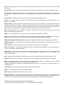
Symptom: Can not access the TT™5800X/TT™2400X through the web browser
Resolution:
•
•
•
•
•
•
Check that the IP address in the URL field is correct.
Check your host computer IP address. If the IP address of the TT™5800X/TT™2400X is 192.168.3.1 then the
host computer IP must set to the 192.168.3.X subnet.
If using the PoE makes sure that you’re using the provided 48V power adapter. Make sure that the
TT™5800X/TT™2400X is connected to the ODU side of the PoE. The computer should be connected to the
NET side of the PoE.
Clear out all internet cache and cookies.
Clear the ARP table by going into the dos prompt and type in the following: arp –d
Reset unit back to factory default by holding down the reset bottom for 10 seconds while the unit is powered
on.
Symptom: Forgot IP address
Resolution:
If you forgot the IP address of the TT™5800X/TT™2400X you can press reset button to restore the default factory
settings by holding down the reset button for 10 seconds. The factory default IP for both SU and AP mode is
192.168.3.1
Symptom: The web control interface graphics isn’t showing up properly
Resolution:
Due to many anti-malware software on the market some features of these programs may disable certain IE functions
which can then lead to pictures not being displayed correctly. If this happens try turning off some of the more restrictive
features of these anti-malware software or try accessing the web control interface with a different browser such as the
firefox.
Symptom: Can not connect to the TT™5800X/TT™2400X with a wireless client
Resolution:
•
•
•
•
•
•
•
Make sure that the client supports the wireless mode that the TT™5800X/TT™2400X is set to.
Make sure that the Mode, SSID (Cap Sensitive), Channel and encryption settings are set the same on both
sides.
Make sure that your computer is within range and free from any strong electrical devices that may cause
interference.
Double check that the wireless client is set to the appropriate transmission speed under the advanced tab of
the wireless connection property.
Temporary disable all securities and encryption settings.
Try it on a different client.
If DHCP is enabled make sure that the client is set to obtain an IP automatically.
Appendix H: Glossary
All Rights Reserved. Copyright 2006 Teletronics International, Inc.
2 Choke Cherry Road, Rockville, MD 20850 Tel: 301.309.8500 Fax: 301.309.8851
802.1x - The standard for wireless LAN authentication used between an AP and a client. 802.1x with EAP will initiate
key handling.
Ad-Hoc Network - The wireless network based on a peer-to-peer communications session. Also referred to as AdHoc.
Access Point - Access points are stations in a wireless LAN that are connected to an Ethernet hub or server. Users
can roam within the range of access points and their wireless device connections are passed from one access point to
the next.
Authentication - Authentication refers to the verification of a transmitted message's integrity.
Beacon - In wireless networking, a beacon is a packet sent by a connected device to inform other devices of its
presence and readiness.
Beacon interval - When a wirelessly networked device sends a beacon, it includes with it a beacon interval, which
specifies the period of time before it will send the beacon again. The interval tells receiving devices on the network
how long they can wait in low-power mode before waking up to handle the beacon. Network managers can adjust the
beacon interval, usually measured in milliseconds (ms) or its equivalent, kilo microseconds (Kmsec).
BSS - Basic Service Set. When a WLAN is operating in infrastructure mode, each access point and its connected
devices are called the Basic Service Set.
BSSID - The unique identifier for an access point in a BSS network. See SSID for more details.
DHCP - DHCP (Dynamic Host Configuration Protocol) software automatically assigns IP addresses to client stations
logging onto a TCP/IP network, which eliminates the need to manually assign permanent IP addresses.
DSSS (Direct Sequence Spread Spectrum) - Method of spreading a wireless signal into wide frequency bandwidth.
Dynamic IP Address - An IP address that is automatically assigned to a client station in a TCP/IP network, typically by
a DHCP server.
DNS (Domain Name System): System used to map readable machine names into IP addresses
DTIM - DTIM (Delivery Traffic Indication Message) provides client stations with information on the next opportunity to
monitor for broadcast or multicast messages.
DTIM interval - A DTIM interval, also known as a Data Beacon Rate, is the frequency at which an access point's
beacon will include a DTIM. This frequency is usually measured in milliseconds (ms) or its equivalent, kilo
microseconds (Kmsec).
ESS - Extended Service Set. ESS is the collective term for two or more BSSs that use the same switch in a LAN.
ESSID - Extended Service Set Identifier. An ESSID is the unique identifier for an ESS. See SSID for more details.
Filter - Filters are schemes, which only allow specified data to be transmitted. For example, the router can filter
specific IP addresses so that users cannot connect to those addresses.
Firmware: Programming inserted into programmable read-only memory, thus becoming a permanent part of a
computing device.
Fragmentation - Refers to the breaking up of data packets during transmission.
Gateway – Is the place where two or more networks connect
IBSS - Independent Basic Service Set. See ad-hoc network
Infrastructure Mode - When a wireless network functions in infrastructure mode, every user communicates with the
network and other users through an access point; this is the typical way corporate WLANs work. An alternative is adhoc mode, but users would have to switch to infrastructure mode to access a network's printers and servers.
All Rights Reserved. Copyright 2006 Teletronics International, Inc.
2 Choke Cherry Road, Rockville, MD 20850 Tel: 301.309.8500 Fax: 301.309.8851
ISP - An ISP is an organization providing Internet access service via modems, ISDN (Integrated Services Digital
Network), and private lines.
LAN(Local Area Network): A group of computers and peripheral devices connected to share resources.
MAC (Medium Access Control) Address: A unique number that distinguishes network cards.
MTU - MTU (Maximum Transmission/Transfer Unit) is the largest packet size that can be sent over a network.
Messages larger than the MTU are divided into smaller packets.
NAT - NAT (Network Address Translation - also known as IP masquerading) enables an organization to present itself
to the Internet with one address. NAT converts the address of each LAN node into one IP address for the Internet (and
vice versa). NAT also provides a certain amount of security by acting as a firewall by keeping individual IP addresses
hidden from the WAN.
Preamble - Preamble refers to the length of a CRC (Cyclic Redundancy Check) block that monitors’ communications
between roaming wireless enabled devices and access points.
Protocol - A standard way of exchanging information between computers.
RADIUS (Remote Authentication Dial In User Service): A server that issues authentication key to clients.
RAM (Random Access Memory): Non-permanent memory.
RIP - RIP (Routing Information Protocol) is a routing protocol that is integrated in the TCP/IP protocol. RIP finds a route
that is based on the smallest number of hops between the source of a packet and its destination.
Router - A router is a device that forwards data packets along networks. The device is connected to at least two
networks, commonly two LANs or WANs or a LAN and an ISP. Routers are located at gateways, the places where two
or more networks connect and use headers and forwarding tables to determine the best path for forwarding the
packets. And they use protocols such as ICMP to communicate with each other and configure the best route between
any two hosts. Very little filtering of data is done through routers.
Roaming - The ability to use a wireless device while moving from one access point to another without losing the
connection.
R T S - RTS (Request To Send) is a signal sent from the transmitting station to the receiving station requesting
permission to transmit data.
Server - Servers are typically powerful and fast machines that store programs and data. The programs and data are
shared by client machines (workstations) on the network.
Static IP Address - A permanent IP address is assigned to a node in a TCP/IP network. Also known as global IP.
Subnet Mask - Subnet Masks (SUBNET work masks) are used by IP protocol to direct messages into a specified
network segment (i.e., subnet). A subnet mask is stored in the client machine, server or router and is compared with an
incoming IP ad-dress to determine whether to accept or reject the packet.
SSID - SSID (Service Set Identifier) is a security measure used in WLANs. The SSID is a unique identifier attached to
packets sent over WLANs. This identifier emulates a password when a wireless device attempts communication on the
WLAN. Because an SSID distinguishes WLANS from each other, access points and wireless devices trying to connect
to a WLAN must use the same SSID.
TCP/IP - TCP/IP (Transmission Control Protocol/Internet Protocol) is the main Internet communications protocol. The
TCP part ensures that data is completely sent and received at the other end. Another part of the TCP/IP protocol set is
UDP, which is used to send data when accuracy and guaranteed packet delivery are not as important (for example, in
real-time video and audio transmission).
TFTP (Trivial File Transfer Protocol) - Simple form of FTP (File Transfer Protocol), which Uses UDP (User Datagram
Protocol), rather than TCP/IP for data transport and provides no security features.
TKIP (Temporal Key Integrity Protocol): An encryption method replacing WEP.TKIP uses random IV and frequent key
exchanges.
UDP (User Datagram Protocol) - A communication method (protocol) that offers a limited amount of service when
messages are exchanged between computers in a network. UDP is used as an alternative
All Rights Reserved. Copyright 2006 Teletronics International, Inc.
2 Choke Cherry Road, Rockville, MD 20850 Tel: 301.309.8500 Fax: 301.309.8851
to TCP/IP.
Uplink: Link to the next level up in a communication hierarchy.
UTP (Unshielded Twisted Pair) cable - Two or more unshielded wires twisted together to form a cable.
Virtual Servers - Virtual servers are client servers (such as Web servers) that share resources with other virtual
servers (i.e., it is not a dedicated server).
WEP (Wired Equivalent Privacy) - An encryption method based on 64 or 128bit algorithm.
WLAN - WLANs (Wireless LANs) are local area networks that use wireless communications for transmitting data.
Transmissions are usually in the 2.4 GHz band. WLAN devices do not need to be lined up for communications like
infrared devices. WLAN devices use access points, which are connected to the wired LAN and provide connectivity to
the LAN. The radio frequency of WLAN devices is strong enough to be transmitted through non-metal walls and
objects, and can cover an area up to a thousand feet. Laptops and notebooks use wireless LAN PCMCIA cards while
PCs use plug-in cards to access the WLAN.
All Rights Reserved. Copyright 2006 Teletronics International, Inc.
2 Choke Cherry Road, Rockville, MD 20850 Tel: 301.309.8500 Fax: 301.309.8851