1
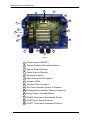
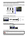
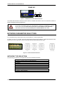
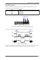
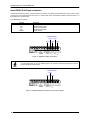
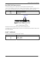
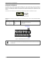
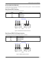
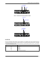
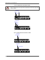
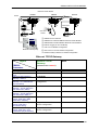
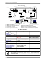
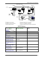
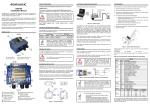
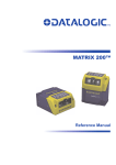
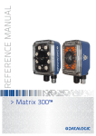
CBX800 INSTALLATION MANUAL 1 2 3 4 5 Figure A NOTE 1 Indicator LEDs 4 Compression Connectors (5) 2 Cover Screws (4) 3 Host Interface Module Panel 5 25-pin Device Connector For a complete Gateway configuration using the Genius™ configuration program, refer to the CBX800 Help On-Line available on the CD. This manual is also downloadable from the Web at www.automation.datalogic.com/cbx800. CBX800 INSTALLATION MANUAL 8 7 7 9 10 6 11 11 5 4 12 3 2 1 13 14 Figure B 1 Power switch (ON/OFF) 2 Source Chassis Grounding Selector 3 Source Shield Selector 4 Power Source Selector 5 Mounting Holes (2) 6 Data Source Port Connector 7 Indicator LEDs 8 Auxiliary Port Connector 9 IP65 Host Interface Module Connector 10 Standard Host Interface Module Connector 11 Spring Clamp Terminal Blocks 12 RS485 Termination Resistance Switch 13 ID-NET/Host Shield Selector 14 ID-NET Termination Resistance Switch 2 CBX800 INSTALLATION MANUAL UPDATES AND LANGUAGE AVAILABILITY UK/US The latest drivers and documentation updates for this product are available on Internet. Log on to: www.automation.datalogic.com I Su Internet sono disponibili le versioni aggiornate di driver e documentazione di questo prodotto. Questo manuale è disponibile anche nella versione italiana. Collegarsi a: www.automation.datalogic.com F Les versions mises à jour de drivers et documentation de ce produit sont disponibles sur Internet. Ce manuel est aussi disponible en version française. Cliquez sur : www.automation.datalogic.com D Im Internet finden Sie die aktuellsten Versionen der Treiber und Dokumentation von diesem Produkt. Die deutschsprachige Version dieses Handbuches ist auch verfügbar. Adresse : www.automation.datalogic.com E En Internet están disponibles las versiones actualizadas de los drivers y documentación de este producto. También está disponible la versión en español de este manual. Dirección Internet : www.automation.datalogic.com SERVICES AND SUPPORT Datalogic provides several services as well as technical support through its website. Log on to www.automation.datalogic.com and click on the links indicated for further information including: PRODUCTS Search through the links to arrive at your product page where you can download specific Manuals and Software & Utilities: - Genius™ a utility program, which allows device configuration using a PC. It provides RS232 and Ethernet interface configuration. SERVICES & SUPPORT - Datalogic Services - Warranty Extensions and Maintenance Agreements - Authorised Repair Centres CONTACT US E-mail form and listing of Datalogic Subsidiaries LEGAL NOTICES © 2009 Datalogic Automation S.r.l. ALL RIGHTS RESERVED. Protected to the fullest extent under U.S. and international laws. Copying, or altering of this document is prohibited without express written consent from Datalogic Automation S.r.l. Datalogic and the Datalogic logo are registered trademarks of Datalogic S.p.A. in many countries, including the U.S.A. and the E.U. ID-NET, and Genius are trademarks of Datalogic Automation S.r.l. All other brand and product names mentioned herein are for identification purposes only and may be trademarks or registered trademarks of their respective owners. Datalogic shall not be liable for technical or editorial errors or omissions contained herein, nor for incidental or consequential damages resulting from the use of this material. 3 CBX800 INSTALLATION MANUAL DESCRIPTION The CBX800 is a Gateway connection box which can be used as an accessory to facilitate system connections for installation and device replacement of several Datalogic family reading devices. It allows connection of devices equipped with a standard RS232/RS485 communication interface to the most common Fieldbus systems, by means of a complete range of optional modules, and to ID-NET™ high speed communication network. System cabling is made through spring clamp terminal blocks inside the CBX800 while the reading device is connected to the CBX800 through a 25-pin connector on the housing. Two 9-pin connectors placed inside the CBX800 facilitate connection to an external PC for data monitoring or for configuring the CBX800 and the reading device. Four embedded rotary switches allow easy manual Network Type and Addressing/Baud Rate selection. CBX800 can also house several accessories which make the system highly flexible. These include: One of several Host Interface Modules - to interface the reader with the most popular Fieldbus network types: Ethernet, Profibus; DeviceNet, etc., including IP65 protection versions. Mounting Adapters – to provide easy mounting to DIN rails and Bosch profiles. PACKAGE CONTENTS Verify that the CBX800 and all the parts supplied with the equipment are present and intact when opening the packaging; the list of parts includes: CBX800 Gateway This Installation Manual Mounting screws and washers (2) CBX800 Configuration CD-ROM Figure 1 - Package Contents 4 CBX800 INSTALLATION MANUAL ACCESSORIES The following accessories are available on request for the CBX800: Name BM200/210 BM300/310 BM400 BM500/510/520 BM600 BM700 BM1100 BM1200/1210 BA100 BA200 BA900 ADP-FF1 Description Ethernet TCP/IP Module STD/IP65 Profibus Module STD/IP65 DeviceNet Module IP65 Ethernet/IP Module STD/IP65/IP54 CANopen Module STD Profinet Module STD CC-Link Module STD Modbus TCP STD/IP65 DIN Rail Adapters Bosch Adapters Two Cable Glands Panel Gender Changer 25P F/F (5 pcs) Part Number 93ACC1851, 93ACC1852 93ACC1810, 93ACC1811 93ACC1814 93ACC1812, 93ACC1813, 93ACC1840 93ACC1815 93ACC1816 93ACC1845 93ACC1848, 93ACC1849 93ACC1821 93ACC1822 93ACC1847 93ACC1827 SUPPORTED READING DEVICES The CBX800 can be directly connected to all of the following readers through the 25-pin connector illustrated in Figure A. Linear Scanners DS6300 2D Readers DS6400 DX6400 DS8100A DX8200A MATRIX-2000™ CBX800 is backward compatible with DS2100N/DS2400N (black body), DS4600A, and DS1100/DS2200 10-30 Vdc model reading devices using the ADP-MM1 25-pin gender changer. See the Gender Changer documentation for the relative CBX pinout. NOTE NOTE For 6K and 8KA Series devices, the software update Package 6.62 allows the 6K/8KA readers to work in a 57.6 Kbps (Low-Speed) ID-NET™ network through a passive CBX100 connection box as Slaves. This requires the entire ID-NET™ network to be configured with this baudrate. For Full-Speed ID-NET™ operation use CBX800. A Hand-Held reader can also be connected to the 25-pin connector and have its data passed through to the Host or ID-NET network. OPENING THE CBX800 To install the CBX800 or during normal maintenance, it is necessary to open it by unscrewing the four cover screws: The CBX800 must be disconnected from the power supply during this operation. CAUTION 5 CBX800 INSTALLATION MANUAL ACCESS TO INTERNAL PARTS To make installation and replacement easier, the CBX800 is made up of three parts: 1) the body of the device containing all electronic components and optional boards 2) the transparent removable cover for inspection and for easy access to spring clamps and internal modules 3) the removable front connector panel providing easy access to the serial and optional interface modules Figure 2 – CBX800 Front Connector Panel 6 CBX800 INSTALLATION MANUAL MECHANICAL INSTALLATION CBX800 can be mounted to various wooden or plastic surfaces using two self-threading screws (3.9 x 45 mm) and washers. Mounting to other surfaces such as concrete walls or metallic panels requires appropriate user-supplied parts (screws, screw anchors, nuts, etc). CBX800 can also be mounted to a DIN rail or a Bosch Frame using the following mounting accessories: BA100 (93ACC1821), BA200 (93ACC1822). The diagram below gives the overall dimensions of the CBX800 and shows the two mounting through-holes. Mounting Holes Figure 3 - Overall Dimensions POWER SUPPLY The power switch (see Figure 4) switches the power supply ON or OFF for both the CBX800 and the connected reading device. CAUTION The power switch does not control power to the Vdc/GND, +V/-V spring clamps, therefore any devices connected to these signals (i.e. external trigger, encoder, etc.), are live and are not protected from polarity inversion. Disconnect the power supply when working inside the CBX800. OFF ON Figure 4 - Power Switch ON/OFF Positions 7 CBX800 INSTALLATION MANUAL NOTE Vdc is electrically connected to +V, just as GND is electrically connected to -V. This is useful for supplying external trigger, inputs and outputs from the CBX800 power source, however +V and -V signals should not be used as power supply inputs to the CBX800. The power supply must be between 10 and 30 Vdc only. SYSTEM WIRING The connection and wiring procedure for CBX800 is described as follows: 1) Open the CBX800 by unscrewing the four cover screws. 2) Verify that the CBX800 power switch is off (see Figure 4). 3) Unscrew the compression connectors and pass all the system cables through them into the CBX800 housing. 4) To connect the power and input/output signals: Prepare the individual wires of the system cables by stripping the insulation back approximately 1 cm. Using a device such as a screwdriver, push down on the lever directly next to the clamp (see Figure 5). Insert the wire into the clamp and release the lever. The wire will now be held in the spring clamp. 5) Tighten the compression connector nuts so that the internal glands seal around the cables. Figure 5 - System Cable Connections Flexible stranded wire should be used and must meet the following specifications. All positions: 24 - 16 AWG 0.2 - 1.5 mm² The CBX800 spring clamp connector pinouts are indicated in the Pinout table. Refer to the reading device Installation Manual for signal details. 8 CBX800 INSTALLATION MANUAL PINOUT Group Input Power External Trigger Input Generic Input Outputs Other I/O Auxiliary (1) Interface ID-NET™ Network Data Source Auxiliary Interface (2) Data Source Interface Host Interface Name Vdc GND Earth +V I1A I1B -V +V I2A I2B -V +V -V O1+ O1O2+ O2O3A O3B +V I3A I4A -V I34B I34B TX RX SGND REF ID+ IDShield TX RX SGND Pinouts Function Power Supply Input Voltage + Power Supply Input Voltage Protection Earth Ground Power Source – External Trigger External Trigger A (polarity insensitive) External Trigger B (polarity insensitive) Power Reference – External Trigger Power Source – Inputs Input 2A (polarity insensitive) Input 2B (polarity insensitive) Power Reference – Inputs Power Source – Outputs Power Reference – Outputs Output 1+ Output 1Output 2+ Output 2Output 3A (polarity insensitive) Output 3B (polarity insensitive) Power Source – Other I/O Input 3A (polarity insensitive) Input 4A (polarity insensitive) Power Reference – Other I/O Input 3B and 4B (common) (polarity insensitive) Input 3B and 4B (common) (polarity insensitive) Auxiliary Interface TX Auxiliary Interface RX Auxiliary Interface Reference Network Reference ID-NET™ network + ID-NET™ network Network Cable Shield Data Source Aux TX Data Source Aux RX Data Source Aux Reference RS232 RS485FD TX TX+ RTS TXRX *RX+ CTS *RXSGND SGND RS232 RS485FD TX TX+ RTS TXRX *RX+ CTS *RXSGND SGND RS485HD RTX+ RTX- SGND RS485HD RTX+ RTX- SGND * Do not leave floating, see Reading Device Reference Manual for connection details. (1) The Auxiliary Interface group is connected to the 9-pin Auxiliary connector and is used for configuring the CBX800 parameters through Genius™, the multilanguage software tool. (2) The Data Source Auxiliary group is connected to the 9-pin Data Source connector and is used for configuring Genius-compatible reading devices through Genius™, the multilanguage software tool. 9 CBX800 INSTALLATION MANUAL The input power signals Vdc, GND and Earth as well as the network signals REF, ID+, ID- and Shield; and RTX+, RTX- and SGND are repeated to facilitate system cabling. In this way the power and network busses can enter and exit the CBX800 from different spring clamps but be physically connected together. NOTE To avoid electromagnetic interference: - Connect CBX800 Protection Earth (Earth) to a good earth ground. - Connect the reading device chassis to earth ground through the jumper, (default setting, seeFigure 7). - Connect the Network Cable Shield (Shield) to Filtered Earth through the jumper (default setting, see Figure 6). Do not connect to the Host Interface spring clamp terminals if using Host Interface Modules (Fieldbus and non Fieldbus). CAUTION JUMPER SETTINGS POWER SOURCE JUMPER SETTINGS For most applications input power is provided through the dedicated spring clamp connectors inside the CBX800. However CBX800 may accept power from the connected reading device through the 25-pin connector. This is useful, for example, to pass power to connected accessories such as Encoder and Presence Sensor from DX8200A VAC models or 6K/8K scanners powered directly through the network. See the relative reading device Reference Manual for details. To power CBX800 from the reading device, the power source jumper must be placed in the "power from device" position as indicated in Figure 6. Power from device Power from clamps (default) Figure 6–Power Source Jumper Settings SOURCE SHIELD JUMPER SETTINGS The reading device shield (Shield) can be connected to Earth Ground (Earth) either directly or through a filter circuit. If the jumper is left open, the network cable shield (Shield) is floating. Equivalent Filter Circuit Earth Floating Filtered Earth (default) Figure 7– Source Shield Jumper Settings 10 CBX800 INSTALLATION MANUAL SOURCE CHASSIS GROUNDING JUMPER SETTINGS The reading device chassis grounding method can be selected by positioning a jumper (see Figure 8 ). In this way the reading device chassis can be connected to earth ground (only if pin Earth is connected to a good earth ground). For all reading devices except 6K/8K, the chassis can alternatively be connected to the power supply ground signal (GND) or it can be left floating but, in this case, the jumper must be removed. For 6K or 8K scanners the chassis is internally connected to GND. All Reading Devices (except 6K/8K) to GND Floating to Earth (default) The scanner chassis is internally connected to GND 6K, 8K Family Scanners to Earth (default) Figure 8 – Chassis Grounding ID-NET/HOST SHIELD JUMPER SETTINGS The Network shield (Shield) can be connected to Earth Ground (Earth) either directly or through a filter circuit. If the jumper is left open, the network cable shield (Shield) is floating. Earth floating Filtered Earth (default) Equivalent Filter Circuit Figure 9 – ID-NET/Host Shield Jumper Settings NETWORK BUS TERMINATION ID-NET™ OFF ON Figure 10 – ID-NET™ Termination Resistance Switch The ID-NET™ termination resistance switch enables or disables the insertion of the bus termination resistor for ID-NET™ network applications. In ID-NET™ network applications the termination resistor must be enabled ONLY on the first and last devices of the chain. On all the other devices this resistor MUST NOT be enabled (OFF). CAUTION 11 CBX800 INSTALLATION MANUAL RS485 HD OFF ON Figure 11 – RS485 HD Termination Resistance Switch The RS485 HD termination resistance switch enables or disables the insertion of the bus termination resistor for RS485 Half Duplex Multidrop applications. In Multiplexer applications the termination resistor must be enabled ONLY on the last device of the chain, the farthest away from the Multiplexer (assuming the Multiplexer is the first device of the chain). On all the other devices this resistor MUST be OFF (disabled). CAUTION This switch must also be OFF (disabled) when Fieldbus Modules are used. NETWORK PARAMETER SELECTORS Four embedded rotary switches allow easy manual selection of network parameters. As shown in Figure 12 , the Net Type rotary switch allows Network Type selection , while three dedicated rotary switches (X1, X10, X100) can be used for manually selecting Addressing and Baud Rate. Figure 12 – Network Parameter Selectors NETWORK TYPE SELECTION The network type depends on the application layout and installed accessories. Net Type Switch 0 = None (no network present or serial multplexer) 1 = Ethernet/IP 2 = Profibus 3 = DeviceNet 4 = CC-Link 5 = Profinet 6 = CANopen 7 = Software Configuration Controlled Host Interface Network 8 = Not Available 9 = ID-NET™ Slave Multidata 12 CBX800 INSTALLATION MANUAL The Net Type selector switch allows setting the Gateway type: Serial (None), Fieldbus, ID-NET™ network: all non network applications (Typology Role = Other) must be set to None (0). ID-NET™ Slaves must be set to Slave Multidata (9), (same ID-NET™ network Topology Role as the ID-NET™ Master). Through the CBX800, several types of accessory Host Interface Modules are available to connect the CBX800 Gateway to a Host network as a Slave node of that network. Note: ID-NET™ Multidata Slaves (9) exclude Host network configuration. The Net Type switch settings (1 – 6) assign the Host network type through the hardware switch; the Node Address is assigned by the Network Address Selection switches. These settings override the software configuration and therefore when used, must match the actual Host Interface Module. The Net Type switch setting Software Configuration Controlled Host Interface Network (7) allows the Host network type and Node Address to be set through the software configuration program; the hardware switches are ignored. This position is valid for all the Host network types including Module types that have no hardware switch position (i.e. Modbus TCP or Ethernet TCP/IP). NETWORK ADDRESS SELECTION Hardware network address selection is provided for rapid installation of ID-NET™ networks and for some of the Host Interface Modules. These switch settings are read at each power-up or reset, and override software configuration settings except where specified otherwise. Valid address selection depends on the network type: Ethernet/IP and Profinet The Ethernet IP or Profinet address refers to the last three digits of the IP address (i.e. 172.16.11.xxx). The valid selection range is from 000 to 255. Address selections outside of this range are not accepted by the network. IP Addressing There are a few special switch settings that allow the software to determine the IP address for Ethernet IP and Profinet interfaces. These settings correspond to the IP Addressing parameter in Genius™. 777 = Remote Assignment through the IPConfig application available on the reader CD-ROM. 888 = Static Assignment – set manually through Genius™ 999 = set through a DHCP server Profibus The valid selection range for the Profibus address is from 000 to 126. Address selections outside of this range are not accepted. Address 126 is a special address which allows the Profibus Master, through software, to set the node address in the range from 000 to 125. DeviceNet The valid selection range for the DeviceNet address is from 00 to 64. Address selections outside of this range are not accepted. The x100 switch is ignored. Address 64 is a special address which allows the DeviceNet Master, through software, to set the node address in the range from 00 to 63. CC-Link The valid selection range for the CC-Link address is from 01 to 64. Address selections outside of this range are not accepted. The x100 switch is ignored. See the Help On-Line Node Address parameter for address restrictions. CANopen The valid selection range for the CANopen address is from 001 to 128. Address selections outside of this range are not accepted. Address 128 is a special address which allows the CANopen Master, through software, to set address and baud rate. ID-NET™ The valid selection range for the ID-NET™ Slave addresses is from 01 to 31. Address selections outside of this range are not accepted by the ID-NET™ network. The x100 switch in this case refers to the ID-NET™ baudrate. 13 CBX800 INSTALLATION MANUAL ELECTRICAL CONNECTIONS POWER SUPPLY CBX00 can accept power from the connected reading device through the 25-pin connector, or through the dedicated spring clamp connector (see section Power Source Jumper Settings). The default jumper setting, requires power to be supplied to the CBX800 through the Vdc and GND pins provided on the spring clamp terminal connector as shown in Figure 13: Power Supply V+ in VGND Earth Ground Figure 13 - Power Supply Connections The power must be between 10 and 30 Vdc only. HOST INTERFACE Do not connect to the Host Interface spring clamp terminals if using Host Interface Modules (Fieldbus and non Fieldbus) with the CBX800. CAUTION Figure 14 – Host Interface Module The signals relative to the following Serial interface types are available on the CBX800 spring clamp terminal blocks. The Host serial interface type and its parameters (baud rate, data bits, etc.) can be defined by the user via Genius™ software. The RS485 half duplex is automatically set whenever MUX32 communication protocol is enabled. For more details refer to the "Communication Settings" section in the Genius™ Help On Line. Details regarding the connections and use of the interfaces are given in the next paragraphs. 14 CBX800 INSTALLATION MANUAL Host RS232 Interface The RS232 interface can be used for connections to the host computer allowing transmission of code data. The following pins are used for RS232 interface connection: Pinout TX RX RTS CTS SGND Function Transmit Data Receive Data Request To Send Clear To Send Signal Ground It is always advisable to use shielded cables. The overall maximum cable length must be less than 15 m (49.2 ft). USER INTERFACE SGND RXD TXD CTS CBX800 SGND TX RTS RX RTS CTS Figure 15 – RS232 Host Interface Connections Using Hardware Handshaking The RTS and CTS signals control data transmission and synchronize the connected devices. +V RTS -V START OF TRANSMISSION END OF TRANSMISSION DATA TRANSMISSION +V TX DATA -V DATA TRANSMISSION C1 C2 C3 C4 C5 TRANSMISSION STOPPED ENABLED +V CTS -V IDLE ENABLED DISABLED IDLE Figure 16 - RS232 Control Signals If the RTS/CTS handshaking protocol is enabled, the reading device activates the RTS output to indicate a message is to be transmitted. The receiving unit activates the CTS input to enable the transmission. 15 CBX800 INSTALLATION MANUAL Host RS485 Full-Duplex Interface The RS485 full-duplex (5 wires + shield) interface is used for non-polled communication protocols in point-to-point connections over longer distances (max 1200 m / 3940 ft) than those acceptable for RS232 communications or in electrically noisy environments. The CBX800 pinout follows: Pinout TX+ RX+ TXRXSGND Function RS485 Transmit Data + RS485 Receive Data + RS485 Transmit Data RS485 Receive Data Signal Ground USER INTERFACE RX485+ TX485+ SGND CBX800 RX485- SGND TX+ TX485- RX+ TX- RX- Figure 17 - RS485 Full-duplex Connections For applications that do not use RX485 signals, do not leave these lines floating but connect them to SGND as shown below. NOTE USER INTERFACE RX485+ SGND CBX800 RX485- SGND TX+ TX- Figure 18 - RS485 Full-duplex Connections using Only TX Signals 16 CBX800 INSTALLATION MANUAL Host RS485 Half-Duplex Interface The RS485 half-duplex (3 wires + shield) interface is used for polled communication protocols. It can be used for Multidrop connections with a Datalogic MX4000 Multiplexer, exploiting a proprietary protocol based on polled mode called MUX32 protocol, where a master device polls slave devices to collect data. Pinout RTX+ RTXSGND Function RS485 Receive/Transmit Data + RS485 Receive/Transmit Data Signal Ground USER INTERFACE RTX485+ SGND CBX800 RTX485- SGND RTX+ RTX- Figure 19 - RS485 Half-duplex Connections This interface is forced by software when the protocol selected is MUX32 protocol. In a Multiplexer layout, the Multidrop address must also be set via serial channel by the Genius™ utility or by the Host Programming Mode. ID-NET™ INTERFACE The following pins are used to connect the ID-NETTM interface: Pinout Shield ID+ IDREF Function Network Cable Shield ID-NET™ network + ID-NET™ network Network Reference 17 CBX800 INSTALLATION MANUAL AUXILIARY INTERFACE All CBX800s have an RS232 auxiliary interface available on the 9-pin connector below, which can be linked to another host computer or an external system. This interface is mainly used for CBX800 configuration through Genius™, the multilanguage software tool. Diagnostics and program downloading can be performed from this interface. Connections can be made to a PC or Laptop using a straight through cable or a USB-RS232 converter. 5 1 9 6 Figure 20 - 9-pin D-Sub Female Connector With reference to the 9-pin connector of Figure 20, the following pins are used to connect the RS232 auxiliary interface: Pin 2 3 5 1, 4, 6, 7, 8, 9 Name TX RX SGND Function Auxiliary Interface Receive Data Auxiliary Interface Transmit Data Signal Ground N.C. USER INTERFACE RX TX Reference Figure 21 - RS232 Auxiliary Interface Connections Do not connect the Aux Interface to the CBX spring clamp connectors and the 9-pin connector simultaneously. NOTE 18 CBX800 INSTALLATION MANUAL DATA SOURCE INTERFACE The Data Source port can be used for configuration and data monitoring purposes. It allows full RS232/RS485 connectivity and is software selectable. Data Source RS232 Interface The following pins are used for RS232 interface connections: Pinout TX RX RTS CTS SGND Function Transmit Data Receive Data Request To Send Clear To Send Signal Ground USER INTERFACE SGND RXD SGND TX CTS TXD RTS RX CTS RTS CBX800 Figure 22 – RS232 Data Source Interface Connections Data Source RS485 Full-Duplex Interface The following pins are used for RS485 Full-duplex interface connections: Pinout TX+ RX+ TXRXSGND Function RS485 Transmit Data + RS485 Receive Data + RS485 Transmit Data RS485 Receive Data Signal Ground USER INTERFACE SGND RX485+ RX485- SGND TX+ TX485+ TX485- TX- RX+ RX- CBX800 Figure 23 - RS485 Full-duplex Connections 19 CBX800 INSTALLATION MANUAL For applications that do not use RX485 signals, do not leave these lines floating but connect them to SGND as shown below. NOTE USER INTERFACE SGND RX485+ RX485- SGND TX+ TXCBX800 Figure 24 - RS485 Full-duplex Connections using Only TX Signals DATA SOURCE AUXILIARY INTERFACE The Data Source Auxiliary Interface available on the 9-pin connector below is used for configuring the external reading device parameters through Genius™, the multilanguage software tool. 5 1 9 6 Figure 25 - 9-pin D-Sub Female Connector With reference to the 9-pin connector of Figure 25, the following pins are used to connect the Data Source Auxiliary Interface: Pin 2 3 5 1, 4, 6, 7, 8, 9 Name TX RX SGND Function Data Source Aux Interface Receive Data Data Source Aux Interface Transmit Data Signal Ground N.C. USER INTERFACE RX TX Reference Figure 26 – Data Source Auxiliary Interface Connections 20 CBX800 INSTALLATION MANUAL INPUTS The two optocoupled polarity insensitive inputs, Input 1 (External Trigger Input) and Input 2, a generic input, available on the CBX800 spring clamp terminal blocks, are managed by the reader connected to the 25-pin connector. These inputs are optocoupled and can be driven by both NPN and PNP type commands. Polarity insensitive inputs assure full functionality even if pins A and B are exchanged. NOTE External Trigger Input (Input 1) The connections are indicated in the following diagram: Pinout +V I1A I1B -V Function Power Source - External Trigger External Trigger A (polarity insensitive) External Trigger B (polarity insensitive) Power Reference - External Trigger EXTERNAL TRIGGER INPUT CONNECTIONS USING CBX800 POWER Power is available directly to the Input Device, independently from the Power Supply Switch inside the CBX800. CAUTION PH-1 Photocell (PNP) (brown) (black) (blue) Figure 27 – PH-1 External Trigger Using CBX800 Power NPN Photocell Power to Photocell Input Signal Photocell Reference Figure 28 - NPN External Trigger Using CBX800 Power 21 CBX800 INSTALLATION MANUAL EXTERNAL TRIGGER INPUT CONNECTIONS USING EXTERNAL POWER PNP Photocell Input Signal Pulled down to External Input Device Reference Figure 29 - PNP External Trigger Using External Power NPN Photocell Pulled up to External Input Device Power Input Signal Figure 30 - NPN External Trigger Using External Power Generic Input (Input 2) Pinout +V I2A I2B -V Function Power Source – Inputs Input 2 A (polarity insensitive) Input 2 B (polarity insensitive) Power Reference - Inputs INPUT 2 CONNECTIONS USING CBX800 POWER Power is available directly to the Input Device, independently from the Power Supply Switch inside the CBX800. CAUTION Input Device Power to Input Device Input Signal Input Device Reference PNP Input 2 Using CBX800 Power 22 CBX800 INSTALLATION MANUAL Input Device Power to Input Input Device Signal Input Device Reference NPN Input 2 Using CBX800 Power INPUT 2 CONNECTIONS USING EXTERNAL POWER Input Device Input Signal Pulled down to External Input Device Reference Figure 31 - PNP Input 2 Using External Power Input Device Pulled up to External Input Device Power Input Signal Figure 32 - NPN Input 2 Using External Power OUTPUTS The two optocoupled general purpose outputs available on the CBX800 spring clamp terminal blocks are managed by the reader connected to the 25-pin connector. The meaning of the two outputs Output 1 and Output 2 can be defined by the user. They are typically used either to signal the data collection result or, for 2D readers, to control an external lighting system. Pinout +V O1+ O1O2+ O2-V Function Power Source - Outputs Output 1 + Output 1 Output 2 + Output 2 Power Reference Outputs 23 CBX800 INSTALLATION MANUAL OUTPUT CONNECTIONS USING CBX800 POWER Power is available directly to the Output Device, independently from the Power Supply Switch inside the CBX800. CAUTION Output Device Power to Output device Output Signal Output device Reference Figure 33 - Open Emitter Output Using CBX800 Power Output Device Power to Output device Output device Reference Output Signal Figure 34 - Open Collector Output Using CBX800 Power OUTPUT CONNECTIONS USING EXTERNAL POWER Output Device Pulled up to External Output Device Power Output Signal Figure 35 - Output Open Emitter Using External Power Output Device Output Signal Pulled down to External Output Device Reference Figure 36 - Output Open Collector Using External Power 24 CBX800 INSTALLATION MANUAL OTHER I/O Two further input signals and one output signal, are available on the CBX800 for readers that support them. These further input/output options are: two optocoupled polarity insensitive inputs (Input 3 and input 4) one optocoupled polarity insensitive output (Output 3) The connections are indicated in the following diagram: Pinout O3A O3B +V I3A I4A -V I34B I34B Function Output 3A (polarity insensitive) Output 3B (polarity insensitive) Power Source – Other I/O Input 3A (polarity insensitive) Input 4A (polarity insensitive) Power Reference – Other I/O Input 3B and 4B (common) (polarity insensitive) Input 3B and 4B (common) (polarity insensitive) 25 CBX800 INSTALLATION MANUAL INDICATOR LEDS blue/red green yellow yellow green green yellow yellow green green Figure 37 – Indicator LEDs There are ten Indicator LEDs which signal power, communication, and I/O activity and are visible from the CBX800 outside cover. The Power LED is blue when power is correctly applied to the CBX800 and the power switch is turned on. This LED is red if power polarity is incorrect. In this case the connected reading device is protected. If external I/O devices are powered through CBX800 (connected to +V/-V), they are not protected from polarity inversion. CAUTION The Ready LED is on after the power-up or reset sequence is complete. The Host, Source, and ID-NET LEDs are active when communicating on the respective interface (fast blinking). The remaining I/O LEDs are active when the respective I/O is active depending on the software configuration setting. 26 CBX800 INSTALLATION MANUAL TYPICAL LAYOUTS The following figure shows the general system layout. Auxiliary Interface Gateway to ID-NET™ Source Auxiliary Interface > BMxxx Fieldbus PWR CBX800 HOST or Gateway to Host I/O Reading Device > BM200 TCP/IP or Serial RS232/RS485 Figure 38 – General System Layout The general system layout allows the CBX800 Gateway to connect any serial device (Hand-Held Reader, 6K, 8KA Scanner, Matrix-2000, etc.), collect its information and send it to a Host over a serial or TCP/IP or Fieldbus interface. Generally the external system Host is connected to the CBX800 Host interface. The reading device connects to the 25-pin connector (Source). The reading device auxiliary interface signals are also available on the internal spring clamp connectors. The ID-NET interface allows any serial device to be connected to a Full-Speed ID-NET™ compatibile network. The dotted lines in the figure refer to optional hardware configurations. A portable PC can be quickly connected to the CBX800 Auxiliary port through the internal 9-pin MUX/GWY connector for CBX800 configuration. Likewise the portable PC can be quickly connected to the Source Auxiliary port through the internal 9-pin Source connector for reader configuration. After making system cabling and switch settings, switch ON the CBX800 power switch (see Figure 4). The Power LED turns on (blue) when the power connection has the correct polarity. The Power LED turns on (red) in case of wrong polarity. After CBX800 configuration and system functioning has been verified, close the CBX800 using the four cover screws. 27 CBX800 INSTALLATION MANUAL Fieldbus Slave Nodes CBX800 Power 6 CBX500 CBX800 2 2 1 3 1 5 DS8100A 5 Matrix 400™ 7 Hand-Held Reader 4 Fieldbus Master (Host) CBX800 Source Interface (RS232) CBX800 Host Interface>BMxxx Fieldbus Module CBX500 Main Interface>BMxxx Fieldbus Module External Trigger (for On-Line Mode) Host Aux for CBX800 Configuration Source Aux for Source Reader Configuration Reader Auxiliary Interface for Reader Configuration Fieldbus Gateway Layout Fieldbus Gateway (ex: Profibus CBX800 Parameters interface board = BM3x0) Net Type Rotary Switch Address Rotary Switches 2 X100 = 0, 1 X10 = 0..9 X1 = 0..9 Other Profibus Topology Role System Layout / Main Port Type Communication Settings / Gateway / Status Communication Settings / Gateway / Data Tx Communication Settings / Gateway / Bus Communication / Node Address Communication Settings / Data Source Serial Port / Data Destination: Gateway Communication Settings / Data Source Serial Port / Termination String Communication Settings / Data Source Serial Port / Line Parameters/ (all parameters) 28 <checked> <checked> Aligned to the Fieldbus Master configuration <checked> Aligned to the Data Source device configuration Aligned to the Data Source device configuration Note Address Range= 00..126 CBX800 INSTALLATION MANUAL Ethernet TCP/IP Nodes CBX800 Power 6 CBX500 CBX800 2 2 1 3 1 5 5 DS6300 Matrix 200™ 7 Hand-Held Reader 4 Ethernet TCP/IP (Host) CBX800 Source Interface CBX800 Host Interface>BM2x0 Ethernet TCP/IP Module CBX500 Main Interface>BM2x0 Ethernet TCP/IP Module External Trigger (for On-Line Mode) Host Aux for CBX800 Configuration Source Aux for Source Reader Configuration Reader Auxiliary Interface for Reader Configuration Ethernet TCP/IP Gateway Layout CBX800 Parameters Net Type Rotary Switch Topology Role System Layout / Main Port Type Communication Settings / Gateway / Data Tx Communication Settings / Gateway / Line Parameters/ (all parameters) Communication Settings / Gateway / TCP/IP Services / User Socket #x / Status Communication Settings / Gateway / TCP/IP Services / User Socket #x / Data Tx Communication Settings / Data Source Serial Port / Data Destination: Gateway Communication Settings / Data Source Serial Port / Termination String Communication Settings / Data Source Serial Port / Line Parameters/ (all parameters) Ethernet TCP/IP Gateway (interface board = BM2x0) Note 7 Other Ethernet TCP/IP <checked> Aligned to the LAN configuration <checked> <checked> <checked> Aligned to the Data Source device configuration Aligned to the Data Source device configuration 29 CBX800 INSTALLATION MANUAL ID-NET™ Slave Nodes CBX800 CBX100 CBX100 Power 2 6 3 3 1 5 7 Matrix 400™ DS6300 DS4800 7 4 ID-NET™ Host 2 Serial (Host) SC4000 ID-NET™ Master CBX800 Source Interface CBX800 Full Speed ID-NET™ Interface Reader ID-NET™ Interface External Trigger (for On-Line Mode) Host 1 Ethernet TCP/IP (WebSentinel) Host Aux for CBX800 Configuration Source Aux for Source Reader Configuration Reader Auxiliary Interface for Reader Configuration ID-NET™ Gateway Layout ID-Net Gateway Note CBX800 Parameters Net Type Rotary Switch Address Rotary Switches Topology Role System Layout / Network Baud Rate (bps) System Layout / Main Port Type Communication Settings / Data Source Serial Port / Data Destination: ID-NET Communication Settings / Data Source Serial Port / Termination String Communication Settings / Data Source Serial Port / Line Parameters/ (all parameters) 9 X100 = 0..9 (ID-Net Baud rate) X10 = 0..3 X1 = 0..9 ID-NET Slave (Multidata) Aligned to the ID-Net Master baud rate Serial (X10 + X1) Address Range = 1..31 <enabled> Aligned to the Data Source device configuration Aligned to the Data Source device configuration DS6K and DS8KA Series devices having software version 6.62, can be connected to an IDNET™ network at (slow speed 56 Kbps) through a CBX100 connection box on the Main communication interface. NOTE 30 CBX800 INSTALLATION MANUAL MUX32 Slave Nodes CBX800 CBX100 CBX100 Power 2 3 3 DS4800 Matrix 400™ 1 5 6 6 4 HandHeld Reader MX4000 MUX32 Serial (Host) CBX800 Source Interface CBX800 Host MUX32 Interface Reader MUX32 Interface External Trigger (for On-Line Mode) Host Aux for CBX800 Configuration Reader Auxiliary Interface for Reader Configuration MUX32 Gateway Layout MUX32 Gateway Note CBX800 Parameters Net Type Rotary Switch Topology Role System Layout / Main Port Type System Layout / Main Port Serial Protocol Communication Settings / Main Serial Port / Data Tx Communication Settings / Main Serial Port / Line Parameters / Baud Rate Communication Settings / Main Serial Port / Line Parameters / MUX32 Protocol Address Communication Settings / Data Source Serial Port / Data Destination: Main Communication Settings / Data Source Serial Port / Termination String Communication Settings / Data Source Serial Port / Line Parameters/ (all parameters) 0 Other Serial MUX 32 slave <enabled> aligned to MUX32 network baud rate enabled on the MUX32 network <enabled> Aligned to the Data Source device configuration Aligned to the Data Source device configuration 31 CBX800 INSTALLATION MANUAL TECHNICAL FEATURES ELECTRICAL FEATURES Supply Voltage Consumption Limited Current Consumption CBX + reading device consumption 10 to 30 Vdc* 0.8 - 0.5 A 2.5 A (see related manual) COMMUNICATION INTERFACES Host Interface Auxiliary Data Source ID-NET™ Communication Protocols USER INTERFACE LED Indicators Configuration Modes PHYSICAL FEATURES Mechanical Dimensions Weight RS232/RS485 up to 115.2 Kbit/s RS232 up to 115.2 Kbit/s RS232/RS485 up to 115.2 Kbit/s RS485 Half Duplex up to 1 Mbaud Datalogic Application Driver (DAD Driver) Power On/Polarity Error (blue/red) Trigger (yellow) IN2 (green) OUT1 (yellow) OUT2 (green) Ready (green) Host (yellow) Source (green) ID-NET (yellow) OUT3 (green) Genius™ utility program Genius™ based Host Mode Programming 193 x 180 x 71 mm (7.6 x 7.1 x 2.8 in.) 830 g. (29.28 oz.) ENVIRONMENTAL FEATURES Operating Temperature 0° to 50 C (+32° to 122 °F) Storage Temperature -20° to 70 C (-4° to 158 °F) Humidity max. Vibration Resistance EN 60068-2-6 90% non condensing 14 mm @ 2 to 10 Hz; 1.5 mm @ 13 to 55 Hz; 2 g @ 70 to 200 Hz; 2 hours on each axis Bump Resistance EN 60068-2-29 30 g; 6 ms; 5000 shocks on each axis Protection Class EN 60529 IP65 ** The features given are typical at a 25 C ambient temperature (if not otherwise indicated). * for further details about minimum/maximum supply voltage refer to the manual of the connected reading device, since the minimum supply voltage required may be >10. ** when compression connectors and reading device are correctly connected. If Host Interface (Fieldbus) Modules are used, only correctly installed IP65 models guarantee IP protection. Protection is not guaranteed when Standard Fieldbus Modules are mounted. 32 CBX800 INSTALLATION MANUAL COMPLIANCE POWER SUPPLY This product is intended to be installed by Qualified Personnel only. This device is intended to be supplied by a UL Listed NEC Class 2 power source. CAUTION Total power consumption is given by adding the CBX800 power consumption to that of all the devices powered through the CBX800 (reading device, P.S., I/O). Refer to the manual of the connected devices for details about minimum/maximum supply voltage and power consumption. Each CBX800 supports only 1 single reading device on the 25-pin connector + system accessories. CE COMPLIANCE Warning: This is a Class A product. In a domestic environment this product may cause radio interference in which case the user may be required to take adequate measures. FCC COMPLIANCE Modifications or changes to this equipment without the expressed written approval of Datalogic could void the authority to use the equipment. This device complies with PART 15 of the FCC Rules. Operation is subject to the following two conditions: (1) This device may not cause harmful interference, and (2) this device must accept any interference received, including interference which may cause undesired operation. This equipment has been tested and found to comply with the limits for a Class A digital device, pursuant to part 15 of the FCC Rules. These limits are designed to provide reasonable protection against harmful interference when the equipment is operated in a commercial environment. This equipment generates, uses, and can radiate radio frequency energy and, if not installed and used in accordance with the instruction manual, may cause harmful interference to radio communications. Operation of this equipment in a residential area is likely to cause harmful interference in which case the user will be required to correct the interference at his own expense. 33 DECLARATION OF CONFORMITY 09 Datalogic Automation S.r.l. Via S. Vitalino 13 40012 - Lippo di Calderara Bologna - Italy dichiara che declares that the déclare que le bescheinigt, daß das Gerät declare que el e tutti i suoi modelli and all its models et tous ses modèles und seine Modelle y todos sus modelos CBX800 Gateway; sono conformi alle Direttive del Consiglio Europeo sottoelencate: are in conformity with the requirements of the European Council Directives listed below: sont conformes aux spécifications des Directives de l'Union Européenne ci-dessous: der nachstehend angeführten Direktiven des Europäischen Rats: cumple con los requisitos de las Directivas del Consejo Europeo, según la lista siguiente: 89/336/EEC EMC Directive e and et und y 92/31/EEC, 93/68/EEC emendamenti successivi further amendments ses successifs amendements späteren Abänderungen succesivas enmiendas Basate sulle legislazioni degli Stati membri in relazione alla compatibilità elettromagnetica ed alla sicurezza dei prodotti. On the approximation of the laws of Member States relating to electromagnetic compatibility and product safety. Basée sur la législation des Etats membres relative à la compatibilité électromagnétique et à la sécurité des produits. Über die Annäherung der Gesetze der Mitgliedsstaaten in bezug auf elektromagnetische Verträglichkeit und Produktsicherheit entsprechen. Basado en la aproximación de las leyes de los Países Miembros respecto a la compatibilidad electromagnética y las Medidas de seguridad relativas al producto. Questa dichiarazione è basata sulla conformità dei prodotti alle norme seguenti: This declaration is based upon compliance of the products to the following standards: Cette déclaration repose sur la conformité des produits aux normes suivantes: Diese Erklärung basiert darauf, daß das Produkt den folgenden Normen entspricht: Esta declaración se basa en el cumplimiento de los productos con las siguientes normas: EN 55022 (Class A ITE), September 1998: INFORMATION TECHNOLOGY EQUIPMENT RADIO DISTURBANCE CHARACTERISTICS LIMITS AND METHODS OF MEASUREMENTS EN 61000-6-2, September 2005: ELECTROMAGNETIC COMPATIBILITY (EMC) PART 6-2: GENERIC STANDARDS - IMMUNITY FOR INDUSTRIAL ENVIRONMENTS Lippo di Calderara, April 21st, 2009 Lorenzo Girotti Product & Process Quality Manager 821001550