1
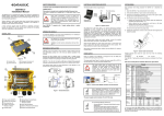
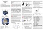
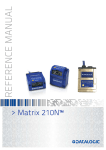
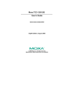
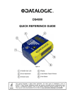
SAFETY PRECAUTIONS ATTENTION: READ THIS INFORMATION BEFORE INSTALLING THE PRODUCT CBX100 LT Installation Manual After system functioning has been verified, close the CBX100 LT using the 2 cover screws. POWER SUPPLY The CBX100 LT is a connection box which can be used as an accessory to facilitate system connections for installation and device replacement of several Datalogic family reading devices specifically designed to be used in subzero temperature applications. System cabling is made through spring clamp terminal blocks inside the CBX100 LT while the reading device is connected to the CBX100 LT through a 25-pin connector on the housing. A 9-pin connector placed inside the CBX100 LT facilitates connection between an external PC and the auxiliary serial interface of the reading device for configuration or data monitoring. This product is intended to be installed by Qualified Personnel only. This device is intended to be supplied by a UL Listed NEC Class 2 power source. CAUTION Switch ON the CBX100 LT power switch (see Figure 3). The Power LED lights (blue) when the power connection has the correct polarity. The Power LED lights (red) in case of wrong polarity. Total power consumption is given by adding the CBX100 LT power consumption to that of all the devices powered through the CBX100 LT (reading device, P.S., I/O). Refer to the manual of the connected devices for details about minimum/maximum supply voltage and power consumption. POWER SUPPLY Power is supplied to the CBX100 LT through the Vdc and GND pins provided on the spring clamp connector. The power switch (see Figure 3) switches the power supply ON or OFF for both the CBX100 LT and the connected reading device. Each CBX100 LT supports only 1 single reading device + system accessories. The power switch does not control power to the Vdc/GND, +V/V spring clamps, therefore any devices connected to these signals (i.e. external trigger, encoder, etc.), are live and are not protected from polarity inversion. Disconnect the power supply when working inside the CBX100 LT. OPENING THE CBX100 LT GENERAL VIEW CAUTION To install the CBX100 LT or during normal maintenance, it is necessary to open it by unscrewing the two cover screws: CBX100 LT Vdc 2 The CBX100 LT must be disconnected from the power supply during this operation. CAUTION V+ (10 - 30 Vdc) GND OFF Installation must be made at a temperature not lower than -20 °C. Group Input Power External Trigger Input Generic Input Outputs POWER SUPPLY CBX100 1 Refer to the reading device Installation Manual for signal details. Auxiliary Interface GND Earth ID-NET™ ON Earth Ground Figure 3 - Power Switch ON/OFF Positions and Connections Network Pinouts Function Power Supply Input Voltage + Power Supply Input Voltage Protection Earth Ground Power Source – External Trigger External Trigger A (polarity insensitive) External Trigger B (polarity insensitive) Power Reference – External Trigger Power Source – Inputs Input 2 A (polarity insensitive) Input 2 B (polarity insensitive) Power Reference – Inputs Power Source – Outputs Power Reference – Outputs Output 1 + Output 1 Output 2 + Output 2 Auxiliary Interface TX Auxiliary Interface RX Auxiliary Interface Reference Network Reference ID-NET™ Network + ID-NET™ Network Network Cable Shield RS232 RS485FD TX TX+ RTS TXRX *RX+ CTS *RXSGND SGND Name Vdc GND Earth +V I1A I1B -V +V I2A I2B -V +V -V O1+ O1O2+ O2TX RX SGND REF ID+ IDShield MECHANICAL INSTALLATION CBX100 LT can be mounted to various wooden or plastic surfaces using the two selfthreading screws (3.9 x 45 mm) and washers provided in the package. 3 Mounting to other surfaces such as concrete walls or metallic panels requires usersupplied parts (screws, screw anchors, nuts, etc). A mounting template is included in the package to facilitate hole drilling alignment. 5 Figure A CBX100 LT can also be mounted to a DIN rail or a Bosch Frame using the following mounting accessories: BA100 (93ACC1821), BA200 (93ACC1822). 4 1 Indicator LEDs 3 Compression Connectors (4) 2 Cover Screws (2) 4 25-pin Decvice Connector NOTE Although the CBX100 LT can be powered between 10 and 30 Vdc, the Subzero readers require 24 Vdc 10%. - 62 [2.4] NOTE 30.8 [1.21] 5 Mounting Holes 138 [5.4] 4 41.4 [1.63] Main Interface The input power signals Vdc, GND and Earth as well as the network signals REF, ID+, ID- and Shield are repeated to facilitate system cabling. In this way the power and network busses can enter and exit the CBX100 LT from different spring clamps but be physically connected together. - Connect CBX100 LT Protection Earth (Earth) to a good earth ground. Connect the reading device chassis to earth ground through the jumper, (default setting, see Figure 7). Connect the Network Cable Shield (Shield) to Filtered Earth through the jumper (default setting, see Figure 6). POWER SOURCE JUMPER SETTINGS For subzero applications input power is provided through the dedicated spring clamp connectors inside the CBX100 LT. Make sure that the Power source jumper is in the default position as shown in the figure below. SYSTEM WIRING 4 [0.16] 4 [0.16] 113.5 [4.47] 128 [5.0] The connection and wiring procedure for CBX100 LT is described as follows: 6 3 43.3 [1.71] 2 1) Open the CBX100 LT by unscrewing the 2 cover screws. 2) Verify that the CBX100 LT power switch is off (see Figure 3). 3) Unscrew the compression connectors and pass all the system cables through them into the CBX100 LT housing. 4) To connect the power and input/output signals: Figure 1 - Overall Dimensions 7 1 Prepare the individual wires of the system cables by stripping the insulation back approximately 1 cm. ELECTRICAL CONNECTIONS AND SETUP Using a device such as a screwdriver, push down on the lever directly next to the clamp (see Figure 4). The following figure shows a typical layout. Insert the wire into the clamp and release the lever. power from device 10 Scanner Auxiliary Interface 8 9 PS, I/O, Main Interface 5) power from clamps (default) Figure 5–Power Source Jumper Settings SHIELD TO PROTECTION EARTH JUMPER SETTINGS The network cable shield (Shield) can be connected to Earth Ground (Earth) either directly or through a filter circuit. If the jumper is left open, the network cable shield (Shield) is floating. The wire will now be held in the spring clamp. PWR SGND To avoid electromagnetic interference: The diagram below gives the overall dimensions of the CBX100 LT and shows the two mounting through-holes. 5 Subzero logo Vdc is electrically connected to +V, just as GND is electrically connected to -V. This is useful for supplying external trigger, inputs and outputs from the CBX100 LT power source, however +V and -V signals should not be used as power supply inputs to the CBX100 LT. RS485HD RTX+ RTX- Earth Tighten the compression connector nuts so that the internal glands seal around the cables. floating Filtered Earth (default) Figure 6– Shield to Protection Earth Jumper Settings Scanner CHASSIS GROUNDING JUMPER SETTINGS Figure B 1 Power switch (ON/OFF) 6 Spring Clamp Terminal Blocks 2 Auxiliary Port Connector 7 RS485 Termination Resistance Switch 3 Mounting Holes (2) 4 ID-NET™ Termination Resistance Switch 8 Power Source Selector 5 Indicator LEDs 10 Chassis Grounding Selector 9 Shield to Protection Earth Selector Reading Device Configuration PC CBX100 LT The reading device chassis grounding method can be selected by positioning a jumper (see Figure 7). In this way the reading device chassis can be connected to earth ground (only if pin Earth is connected to a good earth ground). The reading device chassis can alternatively be connected to the power supply ground signal (GND) or it can be left floating but, in this case, the jumper must be removed. Figure 2 – System Layout The dotted line in the figure refers to an optional (temporary) hardware configuration in which a portable PC can be quickly connected to the CBX100 LT (and consequently to the reading device auxiliary interface) through the internal 9-pin connector. This allows monitoring of the data transmitted by the reading device or configuration through the utility program (see the reading device Installation Manual for more details). The reading device auxiliary interface signals are also available on the internal spring clamp connectors. After making system cabling and switch settings, connect the reading device to the 25pin connector on the CBX100 LT housing. Figure 4 - System Cable Connections to GND floating to Earth (default) Flexible stranded wire should be used and must meet the following specifications. All positions: 24 - 16 AWG 0.2 - 1.5 mm² The CBX100 LT spring clamp connector pinouts are indicated in the Pinout table. Figure 7 – Chassis Grounding 9-PIN READING DEVICE AUXILIARY SERIAL INTERFACE BACKUP AND RESTORE PROCEDURE TECHNICAL FEATURES The reading device auxiliary serial interface available on the internal CBX100 LT 9-pin connector can be used either for configuration or for data monitoring. ELECTRICAL FEATURES Connections can be made to a PC or Laptop using a straight through cable or a USBRS232 converter. Consumption The details of the connector pins are indicated in the following table: CBX100 LT 9-pin D-Sub Female Connector Pinout Supply Voltage Name Function 2 3 5 1, 4, 6, 7, 8, 9 TX RX SGND Auxiliary RS232 Auxiliary RS232 Auxiliary Reference Ground N.C. 5 the Genius™ Device Menu commands (always). 2.5 A Max the BM100 button, (if Fam2/4K scanner X-PRESS™ Key Functionality parameter is enabled) Power On/Polarity Error (blue/red) Trigger (yellow) IN2 (green) OUT1 (yellow) OUT2 (green) 1 9 0.5 to 0.3 A USER INTERFACE LED Indicators Pin The backup and restore functions are valid for any application layout type (point-topoint or ID-NET™ network) using CBX100 LT all-in-one model connection boxes. They can be performed by: 10 to 30 Vdc * Limited Current Consumption CBX + reading device consumption (see related manual) 6 If it ever becomes necessary to replace the reading device it can be quickly configured through the restore procedure. Figure 12 – Address Selection Switches BM100 provides complete backup and restore functions (Configuration and Environmental parameters) and cannot be interrupted once started (LED quickly blinking). BM100 provides hardware network address selection for rapid installation of ID-NET™ networks. These switch settings are read at each power-up or reset, and override software configuration settings. For network nodes, the backup module of the ID-NET™ Master saves the configuration of all the reading devices in the network, Master and all individual Slaves. The Slaves must be configured with the same network baudrate as the Master before performing the Restore procedure. The valid selection range for the ID-NET™ Slave addresses is from 01 to 31. Address selections outside of this range are not accepted by the ID-NET™ network. The x100 switch refers to the ID-NET™ baudrate. For single reading device stations, Slaves, or for RS232 Master/Slave networks, the backup module saves the configuration only of the specific connected reading device. BAUDRATE SELECTION PHYSICAL FEATURES 138 x 128 x 62 mm (5.4 x 5 x 2.4 in.) Mechanical Dimensions NETWORK BUS TERMINATION Weight ID-NET™ about 380 g. (13.40 oz.) ENVIRONMENTAL FEATURES -35° to 50 C (-31° to 122 °F) ** Operating Temperature ON Humidity max. OFF Figure 8 – ID-NET™ Termination Resistance Switch The ID-NET™ termination resistance switch enables or disables the insertion of the bus termination resistor for ID-NET™ network applications. In ID-NET™ network applications the termination resistor must be enabled ONLY on the first and last devices of the chain. On all the other devices this resistor MUST NOT be enabled (OFF). CAUTION 90% non condensing Vibration Resistance 14 mm @ 2 to 10 Hz EN 60068-2-6 2 hours on each axis 1.5 mm @ 13 to 55 Hz 2 g @ 70 to 200 Hz Shock Resistance 3 shocks on each axis Protection Class EN 60529 IP65 (when compression connectors and reading device are correctly connected) OFF Backup Restore No Action 1. 2. Press and hold the Backup & Restore button for approximately 3 seconds. The green Backup LED (B) lights up. 3. Release the button to select Backup and within 1 second press and release it again to activate the procedure. The green Backup LED (B) blinks quickly indicating the backup procedure is active. At the end of the procedure both B and R LEDs turn on for about 2 seconds. When the LEDs turn off the procedure is complete. 4. Set the Write Protection switch to locked. To perform Restore: 1. Press and hold the Backup & Restore button for approximately 6 seconds. The yellow Restore LED (R) lights up. BACKUP AND RESTORE (ALL-IN-ONE MODELS ONLY) 2. Release the button to select Restore and within 1 second press and release it again to activate the procedure. The yellow Restore LED (R) blinks quickly indicating the restore procedure is active. At the end of the procedure both B and R LEDs turn on for about 2 seconds. When the LEDs turn off the procedure is complete. ON 5 Make sure the termination resistance switch is in the OFF position (default). 6 7 ID-NET™ Baudrate Switch 0 = 19200 Baud 5 = 500 kBaud Make sure the Write Protection switch is unlocked. ** Installation must be made at a temperature not lower than -20 °C. Figure 9 – RS485 HD Termination Resistance Switch When the BM100 is used for ID-NET™ network Slaves, the ID-NET™ baudrate is selected through the baudrate switch and must match the Master ID-NET™ baudrate. The settings are: To perform Backup: 30 g; 11 ms; EN 60068-2-27 * for further details about minimum/maximum supply voltage refer to the manual of the connected reading device, since the minimum supply voltage required may be >10 (i.e. 24 Vdc 10% for Subzero readers). RS485 HD These functions are cyclical every 3 seconds: -35° to 70 C (-31° to 158 °F) Storage Temperature NETWORK ADDRESS SELECTION 1 2 blue/red yellow 3 green green 1 Backup/Restore Button 4 ID-NET™ Baudrate Switch 2 Display Connector (not used) 5 ID-NET™ Address Switches 3 Write Protection Lock 6 Backup/Restore Indicator LEDs 7 Network Type Switch Figure 10 – Indicator LEDs There are five Indicator LEDs which signal power and I/O activity and are visible from the CBX100 LT outside cover. The Power LED is blue when power is correctly applied to the CBX100 LT and the power switch is turned on. This LED is red if power polarity is incorrect. In this case the connected reading device and optional Backup Module are protected. The CBX100 LT all-in-one models contain the BM100 Backup Module which provides the following functions: If external I/O devices are powered through CBX100 LT (connected to +V/-V), they are not protected from polarity inversion. CAUTION After releasing the button the first time, do not re-press the button to activate the procedure but wait about 3 seconds (timeout during which the relative LED blinks slowly). NETWORK TYPE SELECTION Figure 11 General View yellow Release the button while both LEDs are off (No Action) Backup and Restore Complete Configuration and Environmental parameter storage for ID-NET™ network and reading devices. Includes write protection. Network Address Selection Hardware Address selection for the ID-NET™ Slave devices (overrides software configuration). Network Type Selection Selection of the ID-NET™ Slave type networking (depends on the application). The network type depends on the application layout. Net Type Switch 0 = None (no network present) or ID-NET™ Master 1 - 7 = Not Available 8 = ID-NET™ Slave Synchronized 9 = ID-NET™ Slave Multidata The Net Type selector switch allows setting the ID-NET™ network: 7 = Reserved 3 = 125 kBaud 8 = Reserved 4 = 250 kBaud 9 = Reserved This reader configuration parameter is enabled by default, so that at startup, the reader sends a message to recognize the presence of, and communicate with, the Backup Module. If using the CBX100 LT all-in-one model, this parameter must be enabled. WRITE PROTECTION LOCK Figure 13 – Write Protection To exit without performing Backup or Restore procedures do one of the following: 6 = 1 MBaud 2 = 57600 Baud SEARCH FOR BACKUP MEMORY AT DEVICE STARTUP 4 INDICATOR LEDS 1 = 38400 Baud A write protection switch is provided to protect configuration data from being inadvertently overwritten. When this switch is in the lock position, the Backup function is not available (data cannot be written to the backup memory) and a diagnostic warning message can be sent. The Restore function is available. SERVICES AND SUPPORT Datalogic provides several services as well as technical support through its website. Log on to www.automation.datalogic.com and click on the links indicated for further information including: PRODUCTS Search through the links to arrive at your product page which describes specific Info, Features, Applications, Models, Accessories, and Downloads. SERVICE - Overview - Warranty Extensions and Maintenance Agreements ID-NET™ Masters communicating with the Host through the main serial interface, and all other non network applications must be set to None (0). - Repair Centers If used for ID-NET™ Slaves, this switch must be set to Slave Synchronized (8) or Slave Multidata (9) depending on the ID-NET™ network Topology Role (same as Master). - Material Return Authorization - Helpdesk CE COMPLIANCE Warning: This is a Class A product. In a domestic environment this product may cause radio interference in which case the user may be required to take adequate measures. See the reading device Reference Manual for the Declaration of Conformity. The remaining four LEDs signal activity on the relative I/O lines. Their meaning depends on the software configuration of the connected reading device. 821001541 (Rev. A)