1
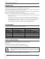
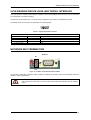
CBX500
INSTALLATION MANUAL
1
2
3
4
5
Figure A
1 Indicator LEDs
2 Cover Screws (4)
3 Fieldbus Interface Panel
4 Compression Connectors (5)
5 25-pin Device Connector
CBX500 INSTALLATION MANUAL
6
7
8
9
10
11
5
4
12
3
13
2
14
1
Figure B
1
Power switch (ON/OFF)
2
Device Chassis Grounding Selector
3
Mounting Holes (2)
4
I/O Extension Module Connector
5
Backup Module Connector
6
Indicator LEDs
7
RS485 Termination Resistance Switch
8
ID-NET™ Termination Resistance Switch
9 Auxiliary Port Connector
10 IP65 Fieldbus Module Connector
11 Standard Fieldbus Module Connector
12 Spring Clamp Terminal Blocks
13 Shield to Protection Earth Selector
14 Power Source Selector
2
CBX500 INSTALLATION MANUAL
UPDATES AND LANGUAGE AVAILABILITY
UK/US
The latest drivers and documentation updates for this product are available on Internet.
Log on to: www.automation.datalogic.com
I
Su Internet sono disponibili le versioni aggiornate di driver e documentazione di questo prodotto. Questo manuale
è disponibile anche nella versione italiana.
Collegarsi a: www.automation.datalogic.com
F
Les versions mises à jour de drivers et documentation de ce produit sont disponibles sur Internet. Ce manuel est
aussi disponible en version française.
Cliquez sur : www.automation.datalogic.com
D
Im Internet finden Sie die aktuellsten Versionen der Treiber und Dokumentation von diesem Produkt. Die
deutschsprachige Version dieses Handbuches ist auch verfügbar.
Adresse : www.automation.datalogic.com
E
En Internet están disponibles las versiones actualizadas de los drivers y documentación de este producto.
También está disponible la versión en español de este manual.
Dirección Internet : www.automation.datalogic.com
SERVICES AND SUPPORT
Datalogic provides several services as well as technical support through its website. Log on to
www.automation.datalogic.com and click on the links indicated for further information including:
•
PRODUCTS
Search through the links to arrive at your product page where you can download specific Manuals and
Software & Utilities:
•
SERVICES & SUPPORT
- Datalogic Services - Warranty Extensions and Maintenance Agreements
- Authorised Repair Centres
•
CONTACT US
E-mail form and listing of Datalogic Subsidiaries
3
CBX500 INSTALLATION MANUAL
DESCRIPTION
The CBX500 is a connection box which can be used as an accessory to facilitate system connections for
installation and device replacement of several Datalogic family reading devices.
System cabling is made through spring clamp terminal blocks inside the CBX500 while the reading device is
connected to the CBX500 through a 25-pin connector on the housing.
A 9-pin connector placed inside the CBX500 facilitates connection between an external PC and the auxiliary serial
interface of the reading device for configuration or data monitoring.
CBX500 can also house several accessories which make the system highly flexible. These include:
•
Backup Module - to backup and restore system configuration parameters making system maintenance
extremely quick and easy.
•
Display Module – to show reading device menu and diagnostic messages at the CBX500.
•
Several Host Interface Modules - to interface the scanner with the most popular Fieldbus
network types: Ethernet, Profibus; DeviceNet, etc., including IP65 protection versions.
•
Mounting Adapters – to provide easy mounting to DIN rails and Bosch profiles.
ACCESSORIES
The following accessories are available on request for the CBX500:
Name
BM100
BM150
BM300/310
BM400
BM500/510/520
BM600
BM700
BM1100
BM1200/1210
BA100
BA200
BA900
Description
Backup Module
Display Module
Profibus Module STD/IP65
DeviceNet Module IP65
Ethernet/IP Module STD/IP65/IP54
CANopen Module STD
Profinet Module STD
CC-Link Module STD
Modbus TCP STD/IP65
DIN Rail Adapters
Bosch Adapters
Two Cable Glands Panel
Part Number
93ACC1808
93ACC1809
93ACC1810, 93ACC1811
93ACC1814
93ACC1812, 93ACC1813, 93ACC1840
93ACC1815
93ACC1816
93ACC1845
93ACC1848, 93ACC1849
93ACC1821
93ACC1822
93ACC1847
SAFETY PRECAUTIONS
ATTENTION: READ THIS INFORMATION BEFORE INSTALLING THE PRODUCT
POWER SUPPLY
This product is intended to be installed by Qualified Personnel only.
This device is intended to be supplied by a UL Listed NEC Class 2 power source.
CAUTION
Total power consumption is given by adding the CBX500 power consumption to that of all the
devices powered through the CBX500 (reading device, P.S., I/O). Refer to the manual of the
connected devices for details about minimum/maximum supply voltage and power
consumption.
Each CBX500 supports only 1 single reading device + system accessories.
4
CBX500 INSTALLATION MANUAL
SUPPORTED READING DEVICE MODELS
The CBX500 can be directly connected to the following readers through the 25-pin connector illustrated in Figure A.
Linear Scanners
2D Readers
DS2100N
DS2400N
DS4800
DS6300
DS6400
DX6400
DS8100A
DX8200A
MATRIX-1000
MATRIX-2000
MATRIX 400
CBX500 is backward compatible with DS4600A, DS2100N/DS2400N (black body), and
DS1100/DS2200 10-30 Vdc model reading devices using the ADP-MM1 25-pin gender changer.
See the Gender Changer documentation for the relative CBX500 pinout.
NOTE
OPENING THE CBX500
To install the CBX500 or during normal maintenance, it is necessary to open it by unscrewing the four cover
screws:
The CBX500 must be disconnected from the power supply during this operation.
CAUTION
5
CBX500 INSTALLATION MANUAL
MECHANICAL INSTALLATION
CBX500 can be mounted to various wooden or plastic surfaces using the two self-threading screws (3.9 x 45 mm)
and washers provided in the package.
Mounting to other surfaces such as concrete walls or metallic panels requires user-supplied parts (screws, screw
anchors, nuts, etc). A mounting template is included in the package to facilitate hole drilling alignment.
CBX500 can also be mounted to a DIN rail or a Bosch Frame using the following mounting accessories: BA100
(93ACC1821), BA200 (93ACC1822).
30.7
[1.21]
71
[2.8]
The diagram below gives the overall dimensions of the CBX500 and shows the two mounting through-holes.
Mounting
Holes
4
[0.16]
178
[7.01]
193
[7.6]
80.9
[3.18]
mm
in
82.9
[3.26]
4
[0.16]
180
[7.1]
Figure 1 - Overall Dimensions
ELECTRICAL CONNECTIONS AND SETUP
The following figure shows the typical layout.
PWR
PS, I/O, Main Interface
Scanner
Auxiliary
Interface
Reading Device
Configuration PC
Scanner
CBX500
Figure 2 – System Layout
The dotted line in the figure refers to an optional (temporary) hardware configuration in which a portable PC can
be quickly connected to the CBX500 (and consequently to the reading device auxiliary interface) through the
internal 9-pin connector. This allows monitoring of the data transmitted by the reading device or configuration
6
CBX500 INSTALLATION MANUAL
through the utility program (see the reading device Installation Manual for more details). The reading device
auxiliary interface signals are also available on the internal spring clamp connectors.
After making system cabling and switch settings, connect the reading device to the 25-pin connector on the
CBX500 housing.
Switch ON the CBX500 power switch (see Figure 3). The Power LED turns on (blue) when the power connection
has the correct polarity. The Power LED turns on (red) in case of wrong polarity.
After system functioning has been verified, close the CBX500 using the four cover screws.
POWER SUPPLY
Power is supplied to the CBX500 through the Vdc and GND pins provided on the spring clamp connector.
The power switch (see Figure 3) switches the power supply ON or OFF for both the CBX500 and the connected
reading device.
CAUTION
The power switch does not control power to the Vdc/GND, +V/-V spring clamps, therefore any
devices connected to these signals (i.e. external trigger, encoder, etc.), are live and are not
protected from polarity inversion. Disconnect the power supply when working inside the
CBX500.
OFF
ON
Figure 3 - Power Switch ON/OFF Positions
POWER SUPPLY
CBX500
Vdc
V+ (10 - 30 Vdc)
GND
GND
Earth
Earth Ground
Figure 4 - Power Supply Connections
NOTE
Vdc is electrically connected to +V, just as GND is electrically connected to -V. This is useful
for supplying external trigger, inputs and outputs from the CBX500 power source, however +V
and -V signals should not be used as power supply inputs to the CBX500.
The power supply must be between 10 and 30 Vdc only.
7
CBX500 INSTALLATION MANUAL
SYSTEM WIRING
The connection and wiring procedure for CBX500 is described as follows:
1) Open the CBX500 by unscrewing the four cover screws.
2) Verify that the CBX500 power switch is off (see Figure 3).
3) Unscrew the compression connectors and pass all the system cables through them into the CBX500 housing.
4) To connect the power and input/output signals:
• Prepare the individual wires of the system cables by stripping the insulation back approximately 1 cm.
• Using a device such as a screwdriver, push down on the lever directly next to the clamp (see Figure 5).
• Insert the wire into the clamp and release the lever.
The wire will now be held in the spring clamp.
5) Tighten the compression connector nuts so that the internal glands seal around the cables.
Figure 5 - System Cable Connections
Flexible stranded wire should be used and must meet the following specifications.
All positions:
24 - 16 AWG
0.2 - 1.5 mm²
The CBX500 spring clamp connector pinouts are indicated in the Pinout table.
Refer to the reading device Installation Manual for signal details.
8
CBX500 INSTALLATION MANUAL
PINOUT
Group
Input Power
External Trigger
Input
Generic Input
Outputs
Other I/O
Auxiliary
Interface
ID-NET™
Network
Main Interface
Name
Vdc
GND
Earth
+V
I1A
I1B
-V
+V
I2A
I2B
-V
+V
-V
O1+
O1O2+
O2O3A
O3B
+V
I3A
I4A
-V
I34B
I34B
TX
RX
SGND
REF
ID+
IDShield
Pinouts
Function
Power Supply Input Voltage +
Power Supply Input Voltage Protection Earth Ground
Power Source – External Trigger
External Trigger A (polarity insensitive)
External Trigger B (polarity insensitive)
Power Reference – External Trigger
Power Source – Inputs
Input 2A (polarity insensitive)
Input 2B (polarity insensitive)
Power Reference – Inputs
Power Source – Outputs
Power Reference – Outputs
Output 1+
Output 1Output 2+
Output 2Output 3A (polarity insensitive)
Output 3B (polarity insensitive)
Power Source – Other I/O
Input 3A (polarity insensitive)
Input 4A (polarity insensitive)
Power Reference – Other I/O
Input 3B and 4B (common) (polarity insensitive)
Input 3B and 4B (common) (polarity insensitive)
Auxiliary Interface TX
Auxiliary Interface RX
Auxiliary Interface Reference
Network Reference
ID-NET™ network +
ID-NET™ network Network Cable Shield
RS232
RS485FD
TX
TX+
RTS
TXRX
*RX+
CTS
*RXSGND
SGND
RS485HD
RTX+
RTX-
SGND
The input power signals Vdc, GND and Earth as well as the network signals REF, ID+, ID- and Shield; and
RTX+, RTX- and SGND are repeated to facilitate system cabling. In this way the power and network busses can
enter and exit the CBX500 from different spring clamps but be physically connected together.
* Do not leave floating, see Reading Device Reference Manual for connection details.
NOTE
To avoid electromagnetic interference:
- Connect CBX500 Protection Earth (Earth) to a good earth ground.
- Connect the reading device chassis to earth ground through the jumper, (default setting, see
Figure 8).
- Connect the Network Cable Shield (Shield) to Filtered Earth through the jumper (default
setting, see Figure 7).
Do not connect to the Main Interface spring clamp terminals if using Host Interface Modules
(Fieldbus).
CAUTION
9
CBX500 INSTALLATION MANUAL
POWER SOURCE JUMPER SETTINGS
For most applications input power is provided through the dedicated spring clamp connectors inside the CBX500.
However CBX500 may accept power from the connected reading device through the 25-pin connector. This is
useful, for example, to pass power to connected accessories such as Encoder and Presence Sensor from DX8200A
VAC models or 6K/8K scanners powered directly through the network. See the relative reading device Reference
Manual for details.
To power CBX500 from the reading device, the power source jumper must be placed in the "power from device"
position as indicated in Figure 6.
power from
device
power from
(default)
clamps
Figure 6–Power Source Jumper Settings
SHIELD TO PROTECTION EARTH JUMPER SETTINGS
The network shield (Shield) can be connected to Earth Ground (Earth) either directly or through a filter circuit. If
the jumper is left open, the network cable shield (Shield) is floating.
Earth
floating
Filtered Earth
(default)
Equivalent
Filter Circuit
Figure 7– Shield to Protection Earth Jumper Settings
CHASSIS GROUNDING JUMPER SETTINGS
The reading device chassis grounding method can be selected by positioning a jumper (see Figure 8). In this way
the reading device chassis can be connected to earth ground (only if pin Earth is connected to a good earth
ground). For all reading devices except 6K/8K, the chassis can alternatively be connected to the power supply
ground signal (GND) or it can be left floating but, in this case, the jumper must be removed. For 6K or 8K
scanners the chassis is internally connected to GND.
All Reading Devices (except 6K/8K)
to GND
floating
to Earth (default)
The scanner chassis is
internally connected to GND
6K, 8K Family Scanners
to Earth (default)
Figure 8 – Chassis Grounding
10
CBX500 INSTALLATION MANUAL
9-PIN READING DEVICE AUXILIARY SERIAL INTERFACE
The reading device auxiliary serial interface available on the internal CBX500 9-pin connector can be used either
for configuration or for data monitoring.
Connections can be made to a PC or Laptop using a straight through cable or a USB-RS232 converter.
The details of the connector pins are indicated in the following table:
5
1
9
6
Figure 9 - 9-pin D-Sub Female Connector
Pin
2
3
5
1, 4, 6, 7, 8, 9
9-pin Connector Pinout
Function
Auxiliary RS232
Auxiliary RS232
Auxiliary Reference Ground
N.C.
Name
TX
RX
SGND
NETWORK BUS TERMINATION
ID-NET™
ON
OFF
Figure 10 – ID-NET™ Termination Resistance Switch
The ID-NET™ termination resistance switch enables or disables the insertion of the bus termination resistor for
ID-NET™ network applications.
CAUTION
In ID-NET™ network applications the termination resistor must be enabled ONLY on the first
and last devices of the chain. On all the other devices this resistor MUST NOT be enabled
(OFF).
11
CBX500 INSTALLATION MANUAL
RS485 HD
ON
OFF
Figure 11 – RS485 HD Termination Resistance Switch
The RS485 HD termination resistance switch enables or disables the insertion of the bus termination resistor for
RS485 Half Duplex Multidrop applications.
In Multiplexer applications the termination resistor must be enabled ONLY on the last device
of the chain, the farthest away from the Multiplexer (assuming the Multiplexer is the first
device of the chain). On all the other devices this resistor MUST be OFF (disabled).
CAUTION
This switch must also be OFF (disabled) when Fieldbus Modules are used.
INDICATOR LEDS
blue/red
yellow
green
yellow
green
Figure 12 – Indicator LEDs
There are five Indicator LEDs which signal power and I/O activity and are visible from the CBX500 outside cover.
The Power LED is blue when power is correctly applied to the CBX500 and the power switch is turned on.
This LED is red if power polarity is incorrect. In this case the connected reading device and optional Backup
Module are protected.
If external I/O devices are powered through CBX500 (connected to +V/-V), they are not
protected from polarity inversion.
CAUTION
The remaining four LEDs signal activity on the relative I/O lines. Their meaning depends on the software
configuration of the connected reading device.
12
CBX500 INSTALLATION MANUAL
TECHNICAL FEATURES
ELECTRICAL FEATURES
Supply Voltage
10 to 30 Vdc*
Consumption
0.8 – 0.5 A
Limited Current Consumption
CBX + reading device consumption
2.5 A
(see related manual)
USER INTERFACE
LED Indicators
Power On/Polarity Error (blue/red)
Trigger (yellow)
IN2 (green)
OUT1 (yellow)
OUT2 (green)
PHYSICAL FEATURES
Mechanical Dimensions
193 x 180 x 71 mm
(7.6 x 7.1 x 2.8 in.)
Weight
about 780 g. (27.5 oz.)
ENVIRONMENTAL FEATURES
Operating Temperature
0° to 50 °C (+32° to 122 °F)
Storage Temperature
-20° to 70 °C (-4° to 158 °F)
Humidity max.
90% non condensing
Vibration Resistance
EN 60068-2-6
2 hours on each axis
14 mm @ 2 to 10 Hz
1.5 mm @ 13 to 55 Hz
2 g @ 70 to 200 Hz
Shock Resistance
EN 60068-2-27
30 g; 11 ms;
3 shocks on each axis
Protection Class
EN 60529
IP65 **
The features given are typical at a 25 °C ambient temperature (if not otherwise indicated).
*
for further details about minimum/maximum supply voltage refer to the manual of the connected reading
device, since the minimum supply voltage required may be >10.
** when compression connectors and reading device are correctly connected.
If Host Interface (Fieldbus) Modules are used, only correctly installed IP65 models guarantee IP protection.
Protection is not guaranteed when Standard Fieldbus Modules are mounted.
COMPLIANCE
POWER SUPPLY
This product is intended to be installed by Qualified Personnel only.
This device is intended to be supplied by a UL Listed NEC Class 2 power source.
CE COMPLIANCE
Warning: This is a Class A product. In a domestic environment this product may cause radio interference in
which case the user may be required to take adequate measures.
13
CBX500 INSTALLATION MANUAL
FCC COMPLIANCE
Modifications or changes to this equipment without the expressed written approval of Datalogic could void the
authority to use the equipment.
This device complies with PART 15 of the FCC Rules. Operation is subject to the following two conditions: (1)
This device may not cause harmful interference, and (2) this device must accept any interference received,
including interference which may cause undesired operation.
This equipment has been tested and found to comply with the limits for a Class A digital device, pursuant to part
15 of the FCC Rules. These limits are designed to provide reasonable protection against harmful interference
when the equipment is operated in a commercial environment. This equipment generates, uses, and can radiate
radio frequency energy and, if not installed and used in accordance with the instruction manual, may cause
harmful interference to radio communications. Operation of this equipment in a residential area is likely to cause
harmful interference in which case the user will be required to correct the interference at his own expense.
14
DECLARATION OF CONFORMITY
08
Datalogic Automation S.r.l.
Via S. Vitalino 13
40012 - Lippo di Calderara
Bologna - Italy
dichiara che
declares that the
déclare que le
bescheinigt, daß das Gerät
declare que el
CBX500 connection box modular;
e tutti i suoi modelli
and all its models
et tous ses modèles
und seine Modelle
y todos sus modelos
sono conformi alle Direttive del Consiglio Europeo sottoelencate:
are in conformity with the requirements of the European Council Directives listed below:
sont conformes aux spécifications des Directives de l'Union Européenne ci-dessous:
der nachstehend angeführten Direktiven des Europäischen Rats:
cumple con los requisitos de las Directivas del Consejo Europeo, según la lista siguiente:
89/336/EEC EMC Directive
e
and
et
und
y
92/31/EEC, 93/68/EEC
emendamenti successivi
further amendments
ses successifs amendements
späteren Abänderungen
succesivas enmiendas
Basate sulle legislazioni degli Stati membri in relazione alla compatibilità elettromagnetica ed alla sicurezza dei prodotti.
On the approximation of the laws of Member States relating to electromagnetic compatibility and product safety.
Basée sur la législation des Etats membres relative à la compatibilité électromagnétique et à la sécurité des produits.
Über die Annäherung der Gesetze der Mitgliedsstaaten in bezug auf elektromagnetische Verträglichkeit und Produktsicherheit
entsprechen.
Basado en la aproximación de las leyes de los Países Miembros respecto a la compatibilidad electromagnética y las Medidas
de seguridad relativas al producto.
Questa dichiarazione è basata sulla conformità dei prodotti alle norme seguenti:
This declaration is based upon compliance of the products to the following standards:
Cette déclaration repose sur la conformité des produits aux normes suivantes:
Diese Erklärung basiert darauf, daß das Produkt den folgenden Normen entspricht:
Esta declaración se basa en el cumplimiento de los productos con las siguientes normas:
EN 55022 (Class A ITE), September 1998:
INFORMATION TECHNOLOGY EQUIPMENT
RADIO DISTURBANCE CHARACTERISTICS
LIMITS AND METHODS OF MEASUREMENTS
EN 61000-6-2, September 2005:
ELECTROMAGNETIC COMPATIBILITY (EMC)
PART 6-2: GENERIC STANDARDS - IMMUNITY FOR INDUSTRIAL
ENVIRONMENTS
Lippo di Calderara, January 29th, 2008
Lorenzo Girotti
Product & Process Quality Manager
821001382 (Rev. B)