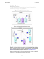
1
MSS User Guide Part Number 900-328 Rev. A 1/04 Copyright & Trademark © 2004, Lantronix. All rights reserved. No part of the contents of this book may be transmitted or reproduced in any form or by any means without the written permission of Lantronix. Printed in the United States of America. Ethernet is a trademark of XEROX Corporation. UNIX is a registered trademark of The Open Group. Windows 95, Windows 98, Windows NT, Windows ME, Windows 2000, and Windows XP are trademarks of Microsoft Corp. Netscape is a trademark of Netscape Communications Corporation. Lantronix Corporate Headquarters 15353 Barranca Parkway Irvine, CA 92618, USA Phone: 949-453-3990 Fax: 949-453-3995 Technical Support Phone: 800-422-7044 or 949-453-7198 Fax: 949-450-7226 Online: www.lantronix.com/support E-mail [email protected] Sales Offices For a current list of our domestic and international sales offices, go to the Lantronix web site at http://www.lantronix.com/about/contact/index.html Contacts Lantronix Corporate Headquarters 15353 Barranca Parkway Irvine, CA 92618, USA Phone:949-453-3990 Fax: 949-453-3995 Technical Support Phone: 800-422-7044 or 949-453-7198 Fax: 949-450-7226 Online: www.lantronix.com/support Email mailto:[email protected] Sales Offices For a current list of our domestic and international sales offices, go to the Lantronix web site at http://www.lantronix.com/about/contact/index.html i Disclaimer & Revisions Operation of this equipment in a residential area is likely to cause interference in which case the user, at his or her own expense, will be required to take whatever measures may be required to correct the interference. Attention: This product has been designed to comply with the limits for a Class A digital device pursuant to Part 15 of FCC Rules. These limits are designed to provide reasonable protection against such interference when operating in a commercial environment. This equipment generates, uses, and can radiate radio frequency energy, and if not installed and used in accordance with this guide, may cause harmful interference to radio communications. Changes or modifications to this device not explicitly approved by Lantronix will void the user's authority to operate this device. The information in this guide may change without notice. The manufacturer assumes no responsibility for any errors that may appear in this guide. ii Contents Copyright & Trademark ________________________________________________ i Disclaimer & Revisions _______________________________________________ ii Contents __________________________________________________________ iii 1: Introduction to the MSS Family ________________________________ 1-1 MSS Family Features _______________________________________________1-1 Protocols _________________________________________________________1-2 Terms ___________________________________________________________1-3 About The Documentation____________________________________________1-3 2: Installation _________________________________________________ 2-1 MSS-VIA Installation ________________________________________________2-1 Components ___________________________________________________2-1 Installation Procedure ____________________________________________2-3 MSS-VIA Specifications __________________________________________2-6 MSS4 Installation___________________________________________________2-7 MSS4 Components ______________________________________________2-7 Installation Procedure ____________________________________________2-8 MSS4 Specifications ____________________________________________2-10 MSS100 Installation________________________________________________2-11 Components __________________________________________________2-11 Installation Procedure ___________________________________________2-12 MSS100 Specifications __________________________________________2-14 3: Getting Started _____________________________________________ 3-15 Privileged User Status ______________________________________________3-15 IP Address Configuration____________________________________________3-16 Using EZWebCon ______________________________________________3-16 Using a Web Browser ___________________________________________3-16 Using ARP and Ping ____________________________________________3-17 Using a DHCP, BOOTP, or RARP Reply ____________________________3-18 Using the Serial Console_________________________________________3-18 Incoming Logins __________________________________________________3-19 Login Password _______________________________________________3-19 Incoming TCP/IP Logins _________________________________________3-19 Serial Port Logins ______________________________________________3-20 iii Remote Console Logins _________________________________________3-21 Incoming LAT Logins ___________________________________________3-21 Changing the Login Password________________________________________3-21 Outbound Connections _____________________________________________3-22 Logout __________________________________________________________3-22 4: Configuration _______________________________________________ 4-1 Overview _________________________________________________________4-1 Rebooting the MSS _________________________________________________4-1 Normal Reboot _________________________________________________4-1 Factory Defaults ________________________________________________4-2 Protocol Configuration _______________________________________________4-2 TCP/IP Configuration ____________________________________________4-2 SNMP ________________________________________________________4-4 IPX (NetWare) Configuration ______________________________________4-5 LAT Configuration _______________________________________________4-7 RS-485 Configuration _______________________________________________4-8 Two-Wire Mode_________________________________________________4-8 Four-Wire Mode ________________________________________________4-9 TXDrive ______________________________________________________4-10 Termination ___________________________________________________4-10 A Note About RS-422 Networking__________________________________4-10 Serial Port Configuration ____________________________________________4-11 Access Mode _________________________________________________4-11 Autostart _____________________________________________________4-11 Serial Data ___________________________________________________4-12 Baud Rate ____________________________________________________4-13 Character Size, Parity, and Stop Bits _______________________________4-13 Flow Control __________________________________________________4-14 Modems and Modem Signaling____________________________________4-14 Logouts ______________________________________________________4-16 Preferred Host_________________________________________________4-17 Dedicated Host ________________________________________________4-17 802.11 Configuration _______________________________________________4-17 Enabling 802.11 Networking ______________________________________4-18 802.11 Region_________________________________________________4-18 MAC Address _________________________________________________4-18 iv Extended Service Set ID (ESSID)__________________________________4-18 Network Mode _________________________________________________4-18 Channel______________________________________________________4-18 WEP ________________________________________________________4-18 Formatting an ATA Flash Card ____________________________________4-18 Modem Cards _________________________________________________4-18 5: Using the MSS _____________________________________________ 5-18 Incoming Connections ______________________________________________5-18 Socket Connections ____________________________________________5-18 Interactive Connections _____________________________________________5-18 Outbound Connections __________________________________________5-18 Session Control________________________________________________5-18 Status Displays ________________________________________________5-18 Serial Tunnel _____________________________________________________5-18 TCP Configuration______________________________________________5-18 UDP Configuration _____________________________________________5-18 Multihost Mode ___________________________________________________5-18 Enabling Multihost Mode_________________________________________5-18 Adding Hosts__________________________________________________5-18 Removing Hosts _______________________________________________5-18 Modem Emulation Mode ____________________________________________5-18 Modem Mode Commands________________________________________5-18 Wiring Requirements____________________________________________5-18 Sequential Hostlist Mode____________________________________________5-18 COM Port Redirector _______________________________________________5-18 6: Troubleshooting ____________________________________________ 6-18 Power-up Troubleshooting __________________________________________6-18 DHCP Troubleshooting _____________________________________________6-18 BOOTP Troubleshooting ____________________________________________6-18 RARP Troubleshooting _____________________________________________6-18 TFTP Troubleshooting______________________________________________6-18 Modem Configuration Checklist_______________________________________6-18 Entering Commands at the Boot Prompt________________________________6-18 Technical Support _________________________________________________6-18 7: Pinouts ___________________________________________________ 7-18 Ethernet Connector ________________________________________________7-18 v MSS VIA Connectors_______________________________________________7-18 PC Card Slot __________________________________________________7-18 Serial Connectors ______________________________________________7-18 MSS4 Connectors _________________________________________________7-18 Serial Connectors ______________________________________________7-18 MSS100 Connectors _______________________________________________7-18 DB25 Connector _______________________________________________7-18 Modem Wiring _________________________________________________7-18 8: Updating Software __________________________________________ 8-18 Obtaining Software ________________________________________________8-18 Via the Web __________________________________________________8-18 Via FTP ______________________________________________________8-18 Reloading Software ________________________________________________8-18 Reloading Sequence____________________________________________8-18 Troubleshooting Flash ROM Updates __________________________________8-18 A: Compliance and Warranty Information _________________________ 8-18 Compliance Information_____________________________________________8-18 Warranty ________________________________________________________8-18 vi 1: Introduction to the MSS Family The Lantronix MSS family of Device Servers allows you to network-enable a variety of serial devices that were not originally designed to be networked: medical devices, retail point of sale terminals, modems, industrial machinery, and more. Typically, an MSS achieves this by providing a serial port on one end and a 10BASE-T or a 10/100BASE-T Ethernet I/O port on the other end. The MSS-VIA provides all the functionality of other MSS products plus a PC card interface, allowing the MSS-VIA to use a variety of technologies such as 802.11b wireless technology, modems, and storage cards. When an 802.11 PC card is installed in the MSS-VIA PC card slot, the MSS-VIA can link its attached serial device to your wireless LAN. This manual assumes knowledge of the IEEE 802.11 Standard governing wireless networking. If you are not familiar with wireless networking concepts and implementation, please refer to the Standard or the documentation that came with your wireless PC card. Note: For a current list of supported PC card technologies, please check the MSS-VIA product page on the Lantronix website: http://www.lantronix.com/. Throughout this manual, the MSS may be referred to as the MSS or as the device server. MSS Family Features TCP/IP and UNIX Compatibility The MSS supports a variety of TCP/IP features, including Telnet, Rlogin, UDP, DNS, SNMP, WINS, FTP, DHCP, BOOTP, RARP, and HTTP. Connectivity The MSS connects serial devices directly to a wired 10/100 BASE-T or wireless 802.11 Ethernet network (for MSS-VIA). Ease of Use The MSS family of products has a simple but powerful command interface for both users and system managers. The MSS Local mode supports command line editing, command line recall, and command completion. An extensive Help facility is included. The EZWebCon utility (provided on the CD-ROM) allows you to configure the MSS from any host machine. It also allows remote host logins into the MSS-VIA, which are similar to Telnet logins. The Lantronix Web Manager allows you to configure the device server using a standard browser. For more information, see Web Browser Login and Configuration. 1-1 MSS User Guide 1: Introduction to the MSS Family Remote Configuration The MSS can be logged into and remotely configured via a network login, a Telnet login to the remote console port, EZWebCon, or a web browser connection to the MSS’ internal HTTP server. Context-Sensitive Help Context-sensitive online help is available from the CLI at any time. You may type HELP by itself for overall help, HELP <command> for help on a specific command, or a partial command line followed by a question mark for help on what is appropriate at that particular point. Note: See the MSS Reference Manual for more information. Reloadable Operating Software The MSS stores its operating code in Flash ROM, which means that it does not have to download code at boot time. If necessary, you can upgrade the MSS operating code to support additional features as newer code becomes available. Also, you can configure the MSS to request a downloaded configuration file at boot time. Security The MSS includes several configurable security features: − Automatic session logouts when a port is disconnected or a device is turned off. − Password protection for privileges, ports, maintenance commands, and the remote console. − An IP security table, which allows the system administrator manager to restrict incoming and outgoing TCP/IP connections to certain ports and hosts. This allows managers to restrict MSS access to a particular local network segment or host. Diagnostics Power-up and interactive diagnostics help system managers troubleshoot network and serial line problems. SDK Support The MSS supports the Lantronix Software Developer Kit (SDK), which allows users to customize the MSS and add functionality. Note: The SDK does not allow users to configure custom PC card support. Protocols A network protocol is a method of communicating over Ethernet (wired or wireless). Each protocol specifies a certain arrangement of data in the Ethernet packets and provides different services for its users. The MSS supports TCP/IP protocols, including Telnet, Rlogin, UDP, DNS, and WINS. The Telnet terminal protocol, supported on most UNIX systems, is an easy-touse interface that creates terminal connections to any network host supporting Telnet. Rlogin is a protocol that allows users to initiate a TCP/IP login session. UDP (User Datagram Protocol) is a connectionless protocol that results in smaller packet headers, no session overhead, and the ability to send to multiple hosts. 1-2 MSS User Guide 1: Introduction to the MSS Family Domain Name Service (DNS) is a protocol that allows a network nameserver to translate text node names into numeric IP addresses. For WINS support, the MSS can be configured to announce itself as a WINS node. Note: MSS products support B-node functionality only The MSS also implements basic Simple Network Management Protocol (SNMP) functionality. SNMP commands enable users, usually system administrators, to get information from and control other nodes on a Local Area Network (LAN), and respond to queries from other network hosts. The MSS allows configuration of one community name with read/write access. Terms The following terms are used throughout this manual. Host A computer attached to the network. The term host is generally used to denote interactive computers, or computers that people can log into. Local Mode The MSS user interface. It is used to issue configuration and session management commands and to establish connections. When in Local mode, users see a Local> prompt. Node Any intelligent device directly connected to the Ethernet network such as a host, a printer, or a terminal server. All nodes have their own Ethernet addresses. The MSS is a node. Devices connected to the MSS are not nodes. Server/server Server, when capitalized, refers to your Lantronix MSS device server product. When not capitalized, it refers to a generic network server machine. Session A logical connection to a service. A typical session is a terminal connected to a host through the device server. About The Documentation The rest of this User Guide is divided into chapters as follows: 2:Installation explains the MSS connectors and the installation process. 3:Getting Started contains configuration information to get the unit up and running. Read this chapter in its entirety, and be sure to configure the required items. 4:Configuration contains additional configuration information. 5:Using the MSS, contains information about how the MSS can be used in different applications. Read this chapter to get the most out of using the MSS in your situation. 1-3 MSS User Guide 1: Introduction to the MSS Family The remaining chapters include 6:Troubleshooting, 7:Pinouts, and 8:Updating Software. Read them as necessary. The MSS Reference Manual, located on the CD-ROM in PDF format, provides the full MSS family command set as well as additional configuration information. Note: All IP addresses, subnet masks, and hardware addresses in this User Guide are examples only. 1-4 2: Installation This chapter covers the installation of the MSS-VIA, MSS4, and MSS100 in a network. Basic knowledge of networking installation is assumed. Read this chapter completely before continuing. MSS-VIA Installation Components The MSS-VIA front panel has a male DB9 RS-232 serial connector, a reset button, and a male DB25 serial connector supporting RS-232, RS-422, or RS-485. Figure 2-1: MSS-VIA Front Panel Note: When the reset button is pressed and held during the power up and boot procedure for at least 3 seconds, the MSS-VIA returns to its factory default configuration. The MSS-VIA rear panel has an RJ45 Ethernet connector, a PC card slot, and a power connector. 2-1 MSS User Guide 2: Installation Figure 2-2. MSS-VIA Rear Panel Five LEDs are located on the top of the unit. The table below explains their functions. Table 2-1: MSS-VIA LEDs LED Function Serial Blinks green to indicate serial activity. OK Blinks green or orange/yellow to indicate network activity. Green: Fast blink (1/2 second) -- the unit is booting; slow blink (2 seconds) -- the unit is running normally Orange/Yellow: Packets sent or received PC Card Blinks yellow, green, or red to indicate PC card status. Off: No PC card inserted Red blinking: PC card not read or not supported Red solid: PC card hardware failure Yellow blinking: Scanning for Access Point (AP) or Ad-Hoc peer Yellow solid: PC card identified, initialization in progress Green blinking: Negotiating settings with AP or Ad-Hoc peer Green solid: 802.11 link established, PC card ready for use 100 Glows green to indicate a 100 Mb Ethernet connection. Link Glows green while the device server is connected properly to a wired 10BASE-T or 100BASE-T Ethernet network. Note: Although a red LED during boot mode usually signals an error, red LED patterns are part of the normal operation of the MSS and are not necessarily indicative of errors or dangerous operation. 2-2 MSS User Guide 2: Installation Installation Procedure The MSS-VIA can be used to network-enable serial devices in either a wired or a wireless network, as shown in the following figures. Figure 2-3: Example Wired Network Layout Figure 2-4: Example Wireless Network Layout The MSS should be positioned close to the device it will be servicing. Since powering down the unit will terminate any active sessions, it may be desirable to place the device server in a location secure from user access. Also be aware of the unit's environmental operating limits and cabling requirements. See Chapter7:Pinouts and MSS-VIA Specifications at the end of this chapter for details. When using a wireless LAN PC card for the network connection, be sure to read the PC card manual for specific placement and distance requirements. 2-3 MSS User Guide 2: Installation The following diagram shows a properly installed MSS-VIA. The numbers in the diagram refer to the installation steps in this section. Figure 2-5: MSS-VIA Connected to Serial Device and Network 1. Connect the MSS to a serial device. a) Connect one end of a serial cable to the MSS DB25 or DB9 connector. See Chapter 7:Pinouts for MSS connector pinout information. You may want to connect a serial terminal to the MSS DB9 console port for the first connection, both to ensure that your device server is working and to configure the necessary network settings. The default settings for the console port are 9600 baud, 8 data bits, one stop bit, no parity, and no flow control. b) Connect the other end of the cable to your serial device's serial port. 2. Connect the MSS to the network via one of the following methods: a) Connect one end of a Category 5 Ethernet cable to the Ethernet network. Connect the other end of the cable to the RJ45 Ethernet port on the back of the MSS. Note: You must use a 10/100BASE-T wired connection if you wish to perform initial configuration via the network. b) Insert an 802.11 wireless PC card into the MSS PC card slot. To see which wireless PC cards the MSS supports, visit the Lantronix Web site at http://www.lantronix.com. Note: Any time you insert a PC card into the MSS PC card slot, you must reboot the MSS so it can identify and initialize the card. Reboot the MSS by removing and replacing the power cord. Do not remove the PC card while the MSS is powered on. 3. Supply power to the MSS. a) Connect the barrel jack end of the power cable to the MSS power jack. b) Connect the power cube end of the power cable to a standard wall outlet. c) When the MSS receives power, it will begin a three-step boot process. 2-4 MSS User Guide 2: Installation d) The MSS runs through a set of power-up diagnostics for approximately five seconds. The OK and Serial LEDs should show varying patterns corresponding to the test being run. Note: The Link LED should remain solid green once the unit has completed booting, assuming there is a valid connection to an Ethernet network. e) The MSS tries to obtain TCP/IP configuration information via DHCP, BOOTP, and/or RARP. This procedure takes approximately 40 seconds if no hosts answer the request. Boot messages will be sent to the console port during the boot process. The OK LED will blink green approximately three times per second, and occasionally yellow, as packets are sent and received. Note: For more information on BOOTP, RARP, or DHCP, refer to your operating system's documentation. f) The MSS determines if the code in the Flash ROMs is valid. If so, it loads the code and begins normal execution. This step takes approximately five seconds. Once the MSS is running normally, the Link LED should be solidly lit to indicate a functioning Ethernet connection, and the OK LED should blink once every two seconds. The PC Card LED should remain lit as long as there is a PC card inserted into the PC card slot. 4. Supply power to the serial device, if necessary. 5. Ensure the MSS is working. There are a few ways to check: Wait for approximately 30 seconds after powering the unit up. If the Link LED is solidly lit and the OK LED blinks green once every two seconds, the MSS is probably operating normally. If you have connected a serial terminal to the MSS DB25 or DB9 port, press the Return or Enter key. You should see several lines of start-up messages followed by a Local> prompt. Ping the MSS from a TCP/IP host. For more instructions, see IP Address Configuration. Figure 2-6: Pinging the MSS % ping nnn.nnn.nnn.nnn 2-5 MSS User Guide 2: Installation MSS-VIA Specifications Power (power cube adaptor) Adapter: Input: 100-240 VAC Universal Power Supply with International Adapters Output: 12 VDC Max Current: 1A @ 12 V MSS-VIA power input range: 7-24 VDC Temperature Note: Rapid temperature changes may affect operation. Do not operate near heating or cooling devices or areas that open to the outdoors. Operating range: 5° to 50° C (41° to 122° F) Storage range: 40° to 66° C (-40° to 151° F) Max. temp change: 20° C (36° F) per hour Humidity Operating range: Storage range: 10% to 90% non-condensing 40% to 60% recommended 10% to 90% non-condensing Altitude Note: For operations above 2.4 km (8,000 ft), decrease the operating temperature rating by 1.8°C for each 1,000 m (1°F for each 1,000 ft). Operating 2.4 km (8,000 ft) Storage 9.1 km (30,000 ft) 2-6 MSS User Guide 2: Installation MSS4 Installation MSS4 Components The following section discusses the specific components for the MSS4-D model. The MSS4-D front panels have four DB9 serial port connectors and an RJ45 Ethernet connector. Figure 2-7: MSS4 Front Panel All models include a reset button and two power connectors. The following figure shows an MSS side panel. Figure 2-8: MSS4 Side Panel LEDs are located on the front panel of the unit. MSS4 units have four LEDs that indicate serial activity for each serial port and two status LEDs. The following tables explains the function of the LEDs. 2-7 MSS User Guide 2: Installation Table 2-2: MSS4 LEDs LED Function Serial (1-4) Blinks green to indicate MSS serial activity. OK Blinks yellow, green, or red to indicate MSS activity. Link Glows green or yellow to indicate a wired Ethernet connection. Off: Not connected to a wired Ethernet network Green: Connected to a 10BASE-T network Yellow: Connected to either a 100BASE-T or 100BASE-FX network Installation Procedure The MSS should be positioned close to the device it will be servicing. Since powering down the unit will terminate any active sessions, it may be desirable to place the device server in a location secure from user access. Also be aware of the unit’s environmental operating limits and cabling requirements. The following diagram shows a properly-installed MSS in an Ethernet network. The numbers in the diagram refer to the installation steps in this section. Figure 2-9: MSS Connected to a Serial Device and Network 1. Connect the MSS to a serial device. Note that all serial ports are initially configured for RS-232 networking. a) Connect one end of a serial cable to one of the MSS DB9 connectors. See Chapter 7:Pinouts for MSS connector pinout information. Note: For the first connection, you may want to connect a serial terminal to the console port, designated as the first serial port. This will allow you to verify that your device server is working and to configure the necessary network settings. The console port is initially set for 9600 baud, 8 data bits, one stop bit, no parity, and no flow control. b) Connect the other end of the cable to your serial device’s serial port. 2-8 MSS User Guide 2: Installation 2. Connect the MSS to the network. Connect one end of a Category 5 Ethernet cable to the Ethernet network. Connect the other end of the cable to the RJ45 Ethernet port on the front of the MSS. 3. Supply power to the MSS. This can be done through either the MSS power jack or the screw terminal power connector. Do not supply power to both the power jack and the screw terminal at the same time. a) Connect one end of a power connector to the MSS via one of the following: Connect the barrel jack end of the power cable to the MSS power jack. Connect power to the 9-30V screw terminal power connector and to ground and chassis ground. Note: The auxiliary input terminal block may be connected only to a SELV circuit. The maximum rating is 30Vdc peak b) Supply power to the MSS by connecting the power cube end of the power cable to a standard wall outlet. When the MSS receives power, it begins the boot process. The MSS runs through a set of power-up diagnostics for approximately five seconds. The OK and Serial LEDs should show varying patterns corresponding to the test being run. Note: If there is a valid connection to a wired Ethernet network, the Link LED should remain solid green or yellow once the unit has completed booting. Once the MSS is running normally, the Link LED should be solidly lit to indicate a functioning wired Ethernet connection and the OK LED should blink once every two seconds. 4. Supply power to the attached serial device(s), if necessary. 5. Ensure the MSS is working: Wait approximately 30 seconds after powering the unit up. If the Link LED is solidly lit and the OK LED blinks green once every two seconds, the MSS is operating normally. If you connected a serial terminal to the console port, press the Return key. You should see several lines of start-up messages followed by a Local> prompt. 2-9 MSS User Guide 2: Installation MSS4 Specifications Power (power cube adaptor) Adapter: Input: 100-240 VAC US Output: 12 VDC Current: 1.5A @ 12VDC MSS4 power input range: 9-30VDC Temperature Note: Rapid temperature changes may affect operation. Do not operate near heating or cooling devices or areas that open to the outdoors. Operating range: 5° to 50° C (41° to 122° F) Storage range: 40° to 66° C (-40° to 151° F) Max. temp change: 20° C (36° F) per hour Humidity Operating range: Storage range: 10% to 90% non-condensing 40% to 60% recommended 10% to 90% non-condensing Altitude Note: For operations above 2.4 km (8,000 ft), decrease the operating temperature rating by 1.8°C for each 1,000 m (1°F for each 1,000 ft). Operating 2.4 km (8,000 ft) Storage 9.1 km (30,000 ft) 2-10 MSS User Guide 2: Installation MSS100 Installation Components The MSS100 front panel has a male DB25 serial connector. The following figure shows an MSS100 front panel. Figure 2-10: MSS100 Front Panel The MSS rear panel has an RJ45 Ethernet connector, a reset button, and a power connector. The following figure shows an MSS100 rear panel. Figure 2-11: MSS100 Rear Panel Note: When the reset button is pressed and held during the power up and boot procedures for at least 3 seconds, the MSS100 returns to its factory default configuration. Five LEDs are located on the top of the unit. The following table explains their functions. 2-11 MSS User Guide 2: Installation Table 2-3: MSS100 LEDs LED Function Power Glows green when power is supplied to the MSS. Link Glows green while the MSS is connected properly to a 10BASE-T or 100BASE-T Ethernet network. 100 Glows green to indicate a 100 Mb Ethernet connection. OK Blinks yellow, green, or red to indicate MSS activity. Serial Blinks yellow, green, or red to indicate MSS activity. Note: Although a red LED during boot mode usually signals an error, red LED patterns are part of the normal operation of the MSS and are not necessarily indicative of errors or dangerous operation. Installation Procedure The MSS can be used to network-enable serial devices as shown in the figure below. Any device with a serial port can be connected to the network via an MSS. Figure 2-12: MSS Network Layout MSS The following diagram shows a properly installed MSS. The numbers in the diagram refer to the installation steps in this section. 2-12 MSS User Guide 2: Installation Figure 2-13: MSS Connected to Serial Device and Ethernet 1. Select a location. The MSS should be positioned close to the device it will be servicing. Since powering down the unit will terminate any active sessions, it may be desirable to place the device server in a location secure from user access. Also be aware of the unit’s environmental operating limits and cabling requirements. 2. Connect the MSS to an RS232-based serial device. a) Connect one end of a serial cable to the DB25 connector on the front of the MSS. You may want to use a serial terminal for the first connection both to ensure that your device server is working and to configure the necessary network settings. Note: The serial port is initially set for 9600 baud, 8 data bits, one stop bit, and no parity. b) Connect the other end of the cable to your serial device’s serial port. 3. Connect the MSS to the Ethernet. a) Connect one end of a Category 5 Ethernet cable to the Ethernet network via a switch or hub, depending on network topology. b) Connect the other end of the cable to the RJ45 Ethernet port on the back of the MSS. The MSS autosenses whether the attached Ethernet connection is 10BASE-T or 100BASE-T. 4. Supply power to the MSS. a) Connect one end of the power cable to the MSS power jack. b) Connect the power cube end of the power cable to a standard wall outlet. When the MSS receives power, it begins the boot process. The MSS runs through a set of power-up diagnostics for approximately five seconds. The Power and Link LEDs should remain solid green. The Link LED should remain solid green. The OK and Serial LEDs should show varying patterns corresponding to the test being run. 2-13 MSS User Guide 2: Installation Once the unit is running normally, the Power LED should be solidly lit to indicate the unit is ON, the Link LED should be solidly lit to indicate a functioning Ethernet connection, and the OK LED should blink green once every two seconds. 5. Supply power to the serial device. 6. Verify that the MSS is working. There are a few ways to check: a) Wait for approximately 30 seconds after powering the unit up. If the Power and Link LEDs are solidly lit and the OK LED blinks green once every two seconds, the MSS is operating normally. b) If you have connected a serial terminal to the MSS DB25 port, press the Return key. You should see several lines of start-up messages followed by a Local> prompt. c) If an IP address is configured for the MSS, ping the MSS from a TCP/IP host. For more instructions, see the IP Address Configuration section in Getting Started. Figure 2-14: Pinging the MSS % ping XXX.XXX.XXX.XXX MSS100 Specifications Power (power cube adaptor) Adapter: Input: 110 VAC US; 100-240 VAC International Output: 5 VDC Current: .74 amps MSS100 power input requirement: 5 VDC regulated Temperature Note: Rapid temperature changes may affect operation. Do not operate near heating or cooling devices or areas that open to the outdoors. Operating range: 5° to 50° C (41° to 122° F) Storage range: 40° to 66° C (-40° to 151° F) Max. temp change: 20° C (36° F) per hour Humidity Operating range: Storage range: 10% to 90% non-condensing 40% to 60% recommended 10% to 90% non-condensing Altitude Note: For operations above 2.4 km (8,000 ft), decrease the operating temperature rating by 1.8°C for each 1,000 m (1°F for each 1,000 ft). Operating 2.4 km (8,000 ft) Storage 9.1 km (30,000 ft) 2-14 3: Getting Started This chapter covers all of the steps needed to get the MSS online and working. There are three basic methods used to log into the MSS and begin configuration. Incoming (Remote) Logins: EZWebCon is the preferred configuration method. Users can also log into the MSS' internal HTTP server via a standard web browser. After the initial configuration, the MSS can be accessed remotely across TCP/IP networks through Telnet connections. Incoming connections also include network socket port connections (ports 2001-2004 and 3001-3004). Serial Port Logins: Users can connect a terminal directly to a serial port, log in, and use the command line interface to configure the unit. Remote Console Logins: TCP/IP users can make a Telnet connection to the remote console port (port 7000). Consider the following points before logging into and configuring the MSS: The MSS IP address must be configured before any TCP/IP functionality is available (see IP Address Configuration). Connecting a terminal to a serial port or logging into the remote console port does not automatically create privileged user status. You must use the Set Privileged command to configure the unit (see Privileged User Status). Only one person at a time may be logged into the remote console port (port 7000). This reduces the possibility of several people simultaneously attempting to configure the MSS. Remote console logins cannot be disabled. The system manager will always be able to access the unit. Privileged User Status Many MSS commands require privileged user (superuser) status. For example, only the privileged user can change server-wide or port-specific settings. To become the privileged user, enter the following command. The default privileged password is system. Figure 3-1: Set Privileged Command Local> SET PRIVILEGED Note: Default passwords pose a security risk and should be changed as soon as possible. This is especially true of the privileged password. If another user is currently the privileged user for the MSS, use the Set Privileged Override command to forcibly become the privileged user. To relinquish privileged status, enter the Set Noprivilege command. 3-15 MSS User Guide 3: Getting Started The privileged password can be changed with the Change Server Privpass command. Specify a new password of up to six alphanumeric characters. Figure 3-2: Changing Privileged Password for MSS-VIA and MSS4 Local> SET PRIVILEGED Password> system (not echoed) Local>> CHANGE SERVER PRIVPASS "walrus" Figure 3-3: Changing Privileged Password for MSS100 Local> SET PRIVILEGED Password> system (not echoed) Local>> CHANGE PRIVPASS "walrus" IP Address Configuration The configuration process includes assigning an IP address. This value is unique and required on the network. Note: When you set an IP address, you may also need to change the subnet mask from the default natural subnet configuration (e.g., 255.255.255.0 for a Class C IP address). See Subnet Mask for more information. Using EZWebCon Use the following steps to assign an IP address using the EZWebCon Expert Shell. 1. Click the Start button on the Windows taskbar, point to Programs, and click EZWebCon to launch EZWebCon. 2. From the Action menu, select Assign IP Address. 3. Enter or change the IP-related settings: a) For Ethernet Address, enter the number that appears on the bottom label of your MSS. b) For IP Address, enter the desired IP address to use for this MSS. c) For Subnet Mask, change the values provided only if you wish to use a mask other than the default. The default value should be correct in most cases. d) For Loadhost, enter the IP address of the network host where you intend to store your operating code and SDK files (if used). 4. Click OK. Note: If you have an older version of EZWebCon, refer to the Readme that was included with it. Using a Web Browser The Web Manager web browser interface can be used to change the IP address once an initial IP address has been configured. The IP address can be changed from the Server Properties subpage or the TCP/IP subpage. See Web Browser Login and Configuration for more information about the Web Manager. 3-16 MSS User Guide 3: Getting Started Using ARP and Ping The ARP/ping method is available under UNIX, Windows 95/98/ME, Windows NT, Windows 2000, and Windows XP. If the MSS is connected to the LAN but has no IP address, it sets its address from the first directed IP packet it receives. Note: The ARP/ping method only works during the first two minutes of MSS operation. After two minutes, an alternate method must be used or the MSS must be rebooted. On a UNIX host, create an entry in the host's ARP table and substitute the intended IP address and the Ethernet address of the device server, and then ping the device server (see the figure below). This process typically requires superuser privileges. Figure 3-4: Entering ARP and Ping (UNIX) # arp -s 192.168.0.10 % ping 192.168.0.10 00:80:a3:xx:xx:xx For the ARP command to work in Windows 95, the ARP table on the PC must have at least one IP address defined other than its own. Type ARP -A at the DOS command prompt to verify that there is at least one entry in the ARP table. If there is no other entry beside the local machine, ping another IP machine on your network to build the ARP table. This has to be a host other than the machine on which you're working. This is not necessary in Windows 98 or above. Use the following commands to ARP the IP address to the MSS and make the MSS acknowledge the IP assignment. Figure 3-5: Entering ARP and Ping (Windows) C:\ ARP -S 192.168.0.10 C:\ PING 192.168.0.10 00-80-A3-XX-XX-XX Note: There should be replies from the IP address if the ARP command worked. When the MSS receives the ping packet, it notices that its IP address is not set and sends out broadcasts to see if another node is using the specified address. If no duplicate is found, the device server uses the IP address and responds to the ping packet. The MSS does not save the learned IP address permanently. This procedure is intended as a temporary measure to enable EZWebCon to communicate with the device server, or allow an administrator to Telnet into the MSS. Once logged in, the administrator can enter the Change Server IPaddress command to make the address permanent. Figure 3-6: Changing the IP Address for MSS-VIA and MSS4 % telnet 192.168.0.10 Trying192.168.0.10 Lantronix Version n.n/n (yymmdd) Type Help at the `Local_>' prompt for assistance. Enter Username> gopher Local> SET PRIVILEGED Password> system (not echoed) Local>> CHANGE SERVER IPADDRESS 192.168.0.10 3-17 MSS User Guide 3: Getting Started Figure 3-7: Changing the IP Address for MSS100 % telnet 192.168.0.10 Trying 192.168.0.10 Lantronix Version n.n/n (yymmdd) Type Help at the `Local_>' prompt for assistance. Enter Username> gopher Local> SET PRIVILEGED Password> system (not echoed) Local>> CHANGE IPADDRESS 192.168.0.10 Using a DHCP, BOOTP, or RARP Reply A host-based DHCP, BOOTP, or RARP server can provide information for the MSS to use to configure an IP address when the unit boots. See the host-based man pages for configuration information. Keep in mind that many BOOTP daemons will not reply to a BOOTP request if the download file name in the configuration file does not exist. If this is the case, create a file in the download path to get the BOOTP daemon to respond. BOOTP and RARP are enabled by default on the MSS. If you wish to disable them, use the Change Server BOOTP Disabled and Change Server RARP Disabled commands. To enable DHCP, use the Change Server DHCP Enabled command. Using the Serial Console If the MSS encounters a problem with the Ethernet network during boot up, it sends an alert message to the console and wait ten seconds to detect serial port activity before attempting to finish booting. If you press a key during that time period, the MSS displays the Boot> prompt at which you can enter the Change IPaddress command to set the unit's IP address. It is recommended to let the MSS complete its normal boot process. Note: For more information on Boot Configuration Program (BCP) commands, see 6:Troubleshooting. Once the MSS completes its boot process, connect a terminal to the serial console and press the Return key. You will see the Local> prompt. Become the privileged user and enter the Change Server IPaddress command. Figure 3-8: Entering the IP Address at the Local Prompt for MSS-VIA and MSS4 Local> SET PRIVILEGED Password> system (not echoed) Local>> CHANGE SERVER IPADDRESS 192.168.0.10 Figure 3-9: Entering the IP Address at the Local Prompt for MSS100 Local> SET PRIVILEGED Password> system (not echoed) Local>> CHANGE IPADDRESS 192.168.0.10 3-18 MSS User Guide 3: Getting Started Incoming Logins Incoming Telnet logins are enabled by default. This behavior can be changed with the Change Server Incoming command and one of the following parameters: Telnet Enables Telnet logins None Disables Telnet logins For security reasons, you may wish to disable incoming logins. If it is undesirable to disable incoming logins, the MSS can be configured to require a login password for incoming connections with the Change Server Incoming Password command. The incoming password feature can be disabled with the Change Server Incoming Nopass command. Login Password The login password is required for remote console logins and when the MSS password protection feature is enabled. The default login password is access. To specify a new login password, use the Change Server Loginpass command and specify a new password of up to six alphabetic characters. Figure 3-10: Changing the Login Password for MSS-VIA and MSS4 Local> SET PRIVILEGED Password> system (not echoed) Local>> CHANGE SERVER LOGINPASS "badger" Figure 3-11: Changing the Login Password for MSS100 Local> SET PRIVILEGED Password> system (not echoed) Local>> CHANGE LOGINPASS "badger" Note: Default passwords may pose a security risk and should be changed as soon as possible. The login password affects both serial ports. Incoming TCP/IP Logins Web Browser Login and Configuration If your MSS has an IP address, you can log into it using a standard web browser with Javascript enabled. Simply type the MSS IP address or resolvable Hostname into the browser's URL/Location field. Figure 3-12: Sample Web Browser Login 3-19 MSS User Guide 3: Getting Started Once you have connected to the MSS, you will see the Lantronix Web Manager interface. Use the left-hand menu to navigate to subpages where you can configure important settings as well as view statistics and other device server information. Figure 3-13. Web Manager Interface EZWebCon Login and Configuration EZWebCon enables users on TCP/IP networks to log into and configure the MSS. The program offers a simple interface that prompts the user for the information necessary to configure the device server. Instructions for installing, running, and using EZWebCon are included on the CD-ROM. Telnet To log into the MSS, type Telnet followed by the MSS IP address. The MSS must have an IP address assigned in order for this command to work. Figure 3-14. A Telnet Connection % telnet 192.168.0.10 Rlogin Rlogin is similar to Telnet. It allows users to connect to a remote device. Rlogin is enabled by default. Figure 3-15: An Rlogin Connection % rlogin 192.168.0.10 Serial Port Logins Attach a terminal to the serial port and press the Return key. The Local> prompt should be displayed. Proceed to 4:Configuration to configure the unit using the command line interface. If there is a problem during the boot process, pressing any key will display the Boot prompt. This prompt enables you to enter a special set of commands, called Boot Configuration Program (BCP) commands, which are discussed in 6:Troubleshooting. 3-20 MSS User Guide 3: Getting Started Remote Console Logins The MSS enables users to configure the device server via a single Telnet connection to the remote console port, designated as port 7000. Connections to the console port cannot be disabled. This ensures that administrators will always be able to log into the port. To connect to the remote console port, use the Telnet command followed by the MSS IP address and the remote console port number. You will have to enter the login password. The default login password is access. Figure 3-16: Connecting to the Console Port % telnet 192.168.0.16 Trying 192.168.0.16 Connected to 192.168.0.16 Escape character is `^]' # access (not echoed) Lantronix MSS Version n.n/n (yymmdd) Type Help at the `Local>' prompt for assistance. Enter Username> jerry Incoming LAT Logins Note: This section refers to MSS100 models only. To get an MSS login prompt when connecting from a LAT host, use the command below. Substitute the last six digits of the MSS hardware address for xxxxxx. Figure 3-17: LAT Login $ SET HOST/LAT MSS_xxxxxx Changing the Login Password The login password is required for remote console logins and when the MSS password protection feature is enabled. The default login password is access. To specify a new login password, use the Change Loginpass command and specify a new password of up to six alphabetic characters. Figure 3-18: Changing the Login Password Local> SET PRIVILEGED Password> system (not echoed) Local>> CHANGE LOGINPASS “badger” Note: Default passwords may pose a security risk and should be changed as soon as possible. This is especially true of the privileged password. 3-21 MSS User Guide 3: Getting Started Outbound Connections When logged into the MSS, users can make basic outgoing connections using the methods described in this section. See the MSS Reference Manual on the CD-ROM for more information about incoming and outgoing connections. Note: Outgoing connections cannot be made via the same method as the incoming connection was made. Thus, if Telnet was used to enter the MSS, it cannot be used to back out. To start an outgoing Telnet session, type Telnet at the Local> prompt, followed by either the host’s name or its numeric IP address. Figure 3-19: Telnet Connection Local> TELNET 192.0.1.66 Logout To manually log out of the MSS, type Logout at the Local> prompt or press Ctrl-D. Figure 3-20: Logging out of the MSS Local> LOGOUT 3-22 4: Configuration Overview Certain parameters must be configured before the MSS can function on the network. Although many users will prefer to use the EZWebCon graphical user interface, this chapter explains how to configure the MSS via the command line interface. Note: Instructions for using EZWebCon are included on the distribution CD-ROM. EZWebCon also has online help to assist you with configuration. The command line interface allows users to enter commands at the Local> prompt to configure, monitor, and use the MSS. This chapter covers the more important MSS commands, such as: Rebooting the MSS Protocol Configuration SNMP IPX (NetWare) Configuration LAT Configuration RS-485 Configuration Rebooting the MSS There are two types of reboots for the MSS. A normal reboot restarts the MSS. A factory reboot restores default configurations for the MSS, removing any custom settings. Normal Reboot You should use a normal reboot if you have configured custom settings that will not take effect until after the MSS has rebooted. Reboot the MSS-VIA if you add or swap PC cards, as PC cards are only scanned at boot time. To reboot the MSS, perform one of the following: At the Local> prompt, enter the Initialize Delay 0 command. At the Boot> prompt, enter the Initialize 451 command. See Entering Commands at the Boot Prompt on page 6-18 for more details. Remove the power cord from the MSS, then plug it back in. 4-1 MSS User Guide 4: Configuration Factory Defaults You should only restore factory default settings if you want to remove all custom configuration from the MSS, including password settings. To restore factory settings to the MSS: From the Local> prompt, enter the Initialize Factory command. From the Boot> prompt, enter the Flush NVR command. Press and hold the reset button down while cycling power to the unit. You must hold the reset button for at least 3 seconds after power is restored. Protocol Configuration TCP/IP Configuration Note: Instructions for initially assigning the MSS IP address are located in IP Address Configuration. IP Address The IP address can be changed with the Change Server IPAddress command. Figure 4-1: Changing the IP Address for MSS-VIA and MSS4 Local>> CHANGE SERVER IPADDRESS 192.168.0.10 Figure 4-2: Changing the IP Address for MSS100 Local>> CHANGE IPADDRESS 192.168.0.10 Subnet Mask IP networks can be divided into several smaller networks by subnetting. When a network is subnetted, some of the host part of each address is given to the network part of the address. The subnet mask denotes how much is given, and allows the device server to decide at connection time whether a given TCP/IP host is part of the local network segment. All hosts must agree on the subnet mask for a given network. When you configure the IP address, a default subnet mask will be configured automatically. This should work for most networks. If your network is divided into subnetworks, you will need to create a custom subnet mask. Use the Change Server Subnet Mask command. Figure 4-3: Setting the Subnet Mask for MSS-VIA and MSS4 Local>> CHANGE SERVER SUBNET MASK 255.255.255.0 Figure 4-4: Setting the Subnet Mask for MSS100 Local>> CHANGE SUBNET MASK 255.255.255.0 Gateway Usually, a TCP/IP internet is broken down into networks and subnetworks, and a host is only able to see the hosts on its own network. TCP/IP networks rely on routers, or gateways, to transfer network traffic to hosts on other networks. Gateways are typically connected to two or more networks and will pass or route TCP/IP packets across network boundaries. 4-2 MSS User Guide 4: Configuration The MSS can be told which hosts are the gateways for the local network. If no gateway is specified, the MSS will listen to network broadcasts from gateways to decide which hosts are acting as gateways. The command below tells the MSS which host is the preferred gateway. Figure 4-5: Specifying a Gateway for MSS-VIA and MSS4 Local>> CHANGE SERVER GATEWAY 192.168.0.10 Figure 4-6: Specifying a Gateway Local>> CHANGE GATEWAY 192.168.0.10 Note: A secondary gateway can also be configured in case the primary gateway is unavailable. If you do not wish to configure a gateway, specify 0.0.0.0 as the IP address in the above command. See Change Server Gateway in the MSS Reference Manual for more information. Name Server A TCP/IP host generally has an alphanumeric host name, such as Phred, in addition to its IP address. For this reason, the MSS supports DNS (Domain Name Service). A DNS Server is a host that can translate text host names into the numeric addresses needed to make a connection. To specify a DNS Server, use the following command: Figure 4-7: Configuring a Nameserver for MSS-VIA and MSS4 Local>> CHANGE SERVER NAMESERVER 192.168.0.22 Figure 4-8: Configuring a Nameserver for MSS100 Local>> CHANGE NAMESERVER 192.168.0.22 A secondary nameserver can also be specified for use when the primary nameserver is unavailable. See Change Server Nameserver in the MSS Reference Manual for more information. Note: If the MSS cannot resolve a text host name, use the numeric IP address. The MSS also allows you to set a default domain name to be appended to any host name for the purpose of name resolution. When a user types a host name, the MSS will add this domain name and attempt the connection. Name checking applies to any MSS commands that require text name resolution, such as Telnet, Rlogin, and Ping. To set the default domain, enter the Change Server Domain command followed by the desired domain name in quotes Figure 4-9: Configuring the Default Domain for MSS-VIA and MSS4 Local>> CHANGE SERVER DOMAIN "xyzcorp.com" Figure 4-10: Configuring the Default Domain for MSS100 Local>> CHANGE DOMAIN "xyzcorp.com" Note: Some nameservers will not resolve host names that do not have a domain at the end. 4-3 MSS User Guide 4: Configuration IP Security IP security allows the system administrator to restrict incoming and outgoing TCP/IP sessions and access to the serial port. Connections are allowed or denied based upon the source IP address (for incoming connections) or the destination IP address (for outgoing connections). IP security information can be added to the IP local host table. To add an entry, specify an IP address and whether to allow (Enabled) or deny (Disabled) connections. For example, the command below disables outgoing connections for all addresses between 192.168.0.1 and 192.168.0.254. Figure 4-11: IP Security Command Local>> CHANGE IPSECURITY 192.168.0.255 DISABLED Single addresses can also be specified. See Change IPSecurity in the MSS Reference Manual for more information. To view the host table entries, enter the Show IPsecurity command. To remove an entry, use the Delete IPSecurity command followed by the IP address that you want to remove. WINS If WINS is enabled, the MSS will broadcast a WINS name announcement at boot time, and answer broadcast WINS name queries. Other hosts can locate the MSS this way. The MSS will rebroadcast whenever its IP address or name changes. Figure 4-12: Enabling WINS for MSS-VIA and MSS4 Local>> CHANGE SERVER WINS ENABLED Figure 4-13: Enabling WINS for MSS100 Local>> CHANGE WINS ENABLED SNMP The MSS supports the SNMP network protocol, which allows hosts on the network to query nodes for counters and network statistics and to change some parameters on those nodes. The form of these requests is documented by RFC 1098. The list of items that can be queried and/or set and the type of data used, such as integer and string, are both documented in various Management Information Bases (MIBs). MIBs cover a variety of things, such as counters and IP address resolution tables. The MSS supports the following MIBs: Table 4-1: Supported MIBS MIB-II (RFC 1213) System, Interface, Address Translation, IP, ICMP, TCP, and UDP, but not the EGP group. Character MIB (RFC 1318) All character-oriented devices. RS232 MIB (RFC 1317) All objects (RS-232-style objects). 4-4 MSS User Guide 4: Configuration The MSS will respond to queries for unknown MIBs with a not in MIB error to the requesting host. SNMP Trap Support The MSS will generate limited forms of three of the SNMP traps. Traps are sent to a host when certain events occur on the MSS. The MSS will generate a Coldstart trap when it first boots, and will send a Linkup trap when the startupfile (if any) has been read from a host and normal operation commences. If a startupfile has been configured but the download fails, the MSS will send an Authentication trap. In all three cases, the trap will be directed to the IP address of the loadhost for the MSS. If a loadhost has not been specified, the traps will not be sent. Configuring SNMP The MSS has a single community (“public”) with read-only access. You can optionally add a single community with read-write access using the Change Server SNMPSetComm command with the MSS-VIA and MSS4 or the Change SNMPSetComm command with the MSS100. See the MSS Reference Manual for more details. Once you enable an SNMP write community, you can configure the following things on the MSS. Items marked with an asterisk (*) are saved to NVR. RS232 MIB: PortInSpeed* (also changes PortOutSpeed) PortOutSpeed* (also changes PortInSpeed) PortInFlowType* (also changes PortOutFlowType) PortOutFlowType * (also changes PortInFlowType) AsyncPortBits* AsyncPortStopBits* AsyncPortParity * AsyncPortAutobaud Character MIB: PortName PortReset PortInFlowType PortOutFlowType PortSessionMaximum SessionKill IPX (NetWare) Configuration Note: The following section on Netware applies to the MSS100 only. Four NetWare settings can be configured: routing and encapsulation parameters, the internal network number to use for internal routing, and the NetWare loadhost to use at boot time. Routing and Encapsulation The first layer of an IPX Ethernet packet is the frame type. It includes routing information. By default, the MSS is configured to handle packets of all four NetWare frame types. If more than one frame type is in use on the LAN, the MSS will advertise itself as a router to the network using its internal network number. This behavior allows nodes and fileservers to access the MSS regardless of the frame type being used. 4-5 MSS User Guide 4: Configuration The MSS can be restricted to a single frame format, in which case it will not do internal routing. Two commands control this behavior: Change NetWare Routing and Change NetWare Encapsulation. Change NetWare Routing enables or disables the use of the internal network number. By default, internal routing is enabled. Note: If two or more frame types are enabled, internal routing must be enabled. To see which frame types are enabled, enter the Show NetWare command. Change NetWare Encapsulation controls which of the frame types are used. The choices are Ether_II, Native, 802_2, and SNAP, which provide for Ethernet v2, 802.3 Native mode, 802.2, and 802.2 SNAP encapsulation types. Figure 4-14 displays an example routing and encapsulation configuration. The 802.3 Native mode and 802.2 SNAP frame types are enabled, while Ethernet v2 and 802.2 are disabled. Because more than one frame type is enabled, internal routing must also be enabled. Figure 4-14: Enabling Selected Frame Types Local>> CHANGE NETWARE ENCAPSULATION NATIVE ENABLED Local>> CHANGE NETWARE ENCAPSULATION SNAP ENABLED Local>> CHANGE NETWARE ENCAPSULATION ETHER_2 DISABLED Local>> CHANGE NETWARE ENCAPSULATION 802_2 DISABLED Local>> CHANGE NETWARE ROUTING ENABLED Internal Network Number When internal routing is enabled, the MSS needs an internal network number that is unique on the network. When addressing IPX packets to a fileserver, devices use the fileserver’s internal network number as the destination address. The internal network number for the MSS is a four-byte number that defaults to the last four bytes of the unit’s Ethernet address (for example, a3001234). It is unlikely that this number will need to be changed. Note: If you do change the internal network number, reboot the MSS. Loadhost A loadhost is a NetWare fileserver from which the MSS will try to load code when the Initialize Reload command is entered. If the software loadfile or loadhost address changes, you will have to change the configured parameters for the next reboot. For the following example, the loadhost is “phred” and the name of the loadfile is “MSS100.SYS”. Figure 4-15: Changing the NetWare Loadhost Local_2>> CHANGE NETWARE LOADHOST phred Local_2>> CHANGE SOFTWARE sys:login/MSS100.SYS 4-6 MSS User Guide 4: Configuration LAT Configuration Note: The following section on LAT configuration applies to the MSS100 only. Three LAT parameters can be configured for the MSS: the device server’s identification string, its service group list, and its internal circuit timer. Server Identification The MSS has a default name that it uses when announcing itself to the LAT network (mss_xxxxxx where xxxxxx represents the last six characters of its hardware address). Users can change the name. Users can also configure a more descriptive identification string. Figure 4-16: LAT Name and Identification Local> CHANGE NAME “Bio5” Local> CHANGE LAT IDENTIFICATION “Biolab 2” Service Groups A service is any resource on the network that can be accessed locally or via a network connection, such as a modem. The MSS serial port and the services on the network each belong to one or more service groups. When a user or device requests a connection to a service, the LAT host will check the service groups to which both the requester and the service belong. If any group number is common to both, the connection attempt will continue. If not, access will be denied. The Change LAT Groups command establishes group numbers for the MSS and its serial port. Figure 4-17: Changing Service Groups Local>> CHANGE LAT GROUPS 1,7,13,105,210-216 Note: Each time the Change LAT Groups command is entered, the previous group list is replaced. Circuit Timer Message transmission on LAT networks is controlled by timers. The MSS circuit timer specifies when messages will be sent from the device server to other network nodes. This timer value is set to a standard default at the factory and should not need to be changed. If you need to change the length of the circuit timer, use the Change LAT CircTimer command followed by a timer value integer. The timer value can range from 30 to 200 milliseconds. Figure 4-18: Changing Timer Delay Local>> CHANGE LAT CIRCTIMER 50 4-7 MSS User Guide 4: Configuration RS-485 Configuration Note: This section applies to MSS models MSS-VIA and MSS4 only. The RS-485 standard allows a serial connection to be shared like a "party line." As many as 32 devices can share the multidrop network. Typically, one device is the master and the other devices are slaves. There are a few important things to note about RS-485 networking with the MSS. MSS-VIA allows for a serial connection on one port. MSS4 allows for a serial connection on all four ports; specify the port when entering RS-485 commands. The MSS can be used in either two-wire or four-wire mode. Refer to the following sections to determine which mode to use. The maximum RS-485 network cabling length (without repeaters) is 4,000 feet. Lantronix recommends the use of shielded twisted-pair cabling. Note: A large number and variety of protocols run over RS-485. However, the MSS does not convert or interpret serial data. It only moves data between serial and Ethernet. Any RS-485 protocol will have to be implemented by host software either on the end device or running internally using the Software Development Kit (SDK) . See 7:Pinouts for information about the RS-485 DB25 connector. To enable RS-485 mode on the MSS, enter the Change RS485 Enabled command. RS232 mode is enabled by default. Figure 4-19: Enabling RS-485 Mode for MSS4 Local> CHANGE RS485 PORT 2 ENABLED Figure 4-20. Enabling RS-485 Mode for MSS-VIA Local> CHANGE RS485 ENABLED Two-Wire Mode In two-wire mode, the MSS operates in half duplex: one pair of wires shares transmit and receive signals, and an optional third wire can be used for shield/ground. The main advantage of using two-wire mode is reduced cabling costs. Figure 4-21: Example Two-Wire Mode Network On a two-wire RS-485 network, the MSS must turn its transmitter on when it is ready to send data and then off a certain period of time after the data has been sent so that the 4-8 MSS User Guide 4: Configuration line is available to receive again. At most baud rate settings, the timing delay is typically one character length with a maximum of 1.5 character lengths. Note: For 600 baud and 4800 baud operation, the timing delay is doubled. Figure 4-22: Enabling Two-Wire RS-485 Mode for MSS4 Local> CHANGE RS485 PORT 2 MODE 2WIRE Figure 4-23: Enabling Two-Wire RS-485 Mode for MSS-VIA Local> CHANGE RS485 MODE 2WIRE Note: For two-wire mode, the TXDrive setting must be set to Automatic (see TXDrive on page 4-10). If you enable two-wire mode and TXDrive is set for Always, the MSS returns an error. Four-Wire Mode In four-wire mode, the MSS operates in full duplex: one pair of wires functions as the transmit pair, another pair of wires functions as the receive pair, and there is a shield/ground wire for each pair. In a four-wire RS-485 network, one device acts as master while the other devices are slaves. Figure 4-24. Example Four-Wire Mode Network It is important to connect the transmitter of the master device to the wire that is connected to the receive terminals on the slave devices, and connect the receiver of the master device to the wire that is connected to the transmit terminals on the slave devices. In essence, the master device will be connected to the slave devices with a swapped cable. In four-wire mode, the MSS is able to send and receive data simultaneously. The advantages of four-wire mode are double the throughput of two-wire mode and a guaranteed open path to each slave device's receiver. Figure 4-25: Enabling Four-Wire RS-485 Mode for MSS4 Local> CHANGE RS485 PORT 2 MODE 4WIRE Figure 4-26: Enabling Four-Wire RS-485 Mode for MSS-VIA Local> CHANGE RS485 MODE 4WIRE 4-9 MSS User Guide 4: Configuration TXDrive The MSS-VIA can be configured to always drive the TX (transmit) signal, or tri-state (transmit, receive, or ignore) when not actively transmitting. The Change RS485 TXDrive command takes one of two parameters. The Always parameter sets the MSS for continuous TXDrive, both high and low. The Automatic parameter sets the MSS for TXDrive only when transmitting. Figure 4-27: Changing TXDrive for MSS4 Local>> CHANGE RS485 PORT 2 TXDRIVE AUTOMATIC Figure 4-28: Changing TXDrive for MSS-VIA Local>> CHANGE RS485 TXDRIVE AUTOMATIC Note: You can only set TXDrive for Always when using four-wire mode. It must be set to Automatic for two-wire mode. Termination RS-485 connections must be terminated properly in order to work. Termination is necessary when using long cable runs, although only end nodes should be terminated. Figure 4-29: Enabling RS-485 Termination for MSS4 Local> CHANGE RS485 PORT 2 TERMINATION ENABLED Figure 4-30: Enabling RS-485 Termination for MSS-VIA Local> CHANGE RS485 TERMINATION ENABLED Slave devices should be set for automatic termination using the Change 485 Termination TX Auto command. A Note About RS-422 Networking The MSS is compatible with RS-422 networks in four-wire RS-485 mode. Connect the MSS to a single slave device using a swapped cable, as shown below, and configure the MSS as if you were going to use it for four-wire RS-485 networking. 4-10 MSS User Guide 4: Configuration Figure 4-31: RS-422 Connection The MSS drives handshaking signals (CTS, RTS, DTR, DSR, and CD) at RS-232 level, and listens for those signals at RS-232 level. Serial Port Configuration The serial ports are set at the factory for 9600 baud, 8 data bits, one stop bit, and no parity. To make port settings take effect, type LOGOUT PORT n (where n is the port number). Some port settings take effect immediately upon entering the command. Note: The DB25 is Port 1, and the DB9 is Port 2. Port 1 is used in the example commands. Access Mode The serial port access mode governs which connections the port can accept. Local access permits local logins on the serial port. Remote access allows network hosts to connect to the MSS serial port. Dynamic access (the default) allows both local and remote access. To change the serial port's access mode, enter the Change Port Access command. Figure 4-32: Changing Serial Port Access Mode for MSS-VIA and MSS4 Local>> CHANGE PORT 1 ACCESS LOCAL Figure 4-33: Changing Serial Port Access Mode for MSS100 Local>> CHANGE ACCESS LOCAL Autostart Normally, the serial port will wait for a carriage return before starting a connection. When the Autostart option is enabled, the MSS will establish a connection as soon as it boots (or if modem control is enabled, as soon as the DSR signal is asserted). To control this feature, enter the Change Port Autostart command. Figure 4-34: Enabling Autostart for MSS-VIA and MSS4 Local>> CHANGE PORT 1 AUTOSTART ENABLED Figure 4-35: Enabling Autostart for MSS100 Local>> CHANGE AUTOSTART ENABLED A port set for Autostart will never be idle, and therefore will not be available for network connections. If incoming network connections are desired, Autostart should remain disabled (the default). 4-11 MSS User Guide 4: Configuration Autostart can also be triggered by a specific input character. There is no default Autostart character; you will have to configure one. For example, when using Modem Emulation Mode you may want to use A so that Autostart will happen as soon as an AT modem command is entered. Keep in mind that when you configure an Autostart character, you can no longer use <CR> to get to the Local> prompt. Figure 4-36: Configuring an Autostart Character for MSS-VIA and MSS4 Local>> CHANGE PORT 1 AUTOSTART CHARACTER "A" Figure 4-37: Configuring an Autostart Character for MSS100 Local>> CHANGE AUTOSTART CHARACTER "A" Serial Data Once a connection has been started, several different triggers can be used to transmit all accumulated serial data to the host. These options are controlled with the Change Port Datasend command. The datasend process used by the MSS balances network traffic with latency concerns. One kind of trigger can be set by specifying a “timeout” condition of either the time since the last character was received (with the Timeout Idle parameter) or the time since the current character burst was started (with the Timeout Frame parameter). For example, to trigger data transmission 150 milliseconds after the current character burst began, enter the following command: Figure 4-38: Transmitting Serial Data with Trigger Delay for MSS-VIA and MSS4 Local>> CHANGE PORT 1 DATASEND TIMEOUT FRAME 150 Figure 4-39: Transmitting Serial Data with Trigger Delay for MSS100 Local>> CHANGE DATASEND TIMEOUT FRAME 150 The examples in Figure 4-38 and Figure 4-39 can be visualized as: x x x xxx xx (data) x x xx xxxxxxxx xx xxxx xx xxxx |-------------------------------------------------------| 150 milliseconds transmit packet Another option is to set a one- or two-character trigger that will cause the MSS to transmit the data. You can also specify whether the trigger characters will be sent to the host as part of the serial data or whether they should be discarded (the default). For example, the following commands will cause the accumulated serial data to transmit as soon as the “Z” character is detected in the data stream and to send the matched character (“Z”) to the host as part of that data. Figure 4-40: Transmitting Serial Data with a Character Trigger for MSS-VIA and MSS4 Local>> CHANGE PORT 1 DATASEND CHARACTER Z Local>> CHANGE PORT 1 DATASEND SAVE 1 Figure 4-41: Transmitting Serial Data with a Character Trigger for MSS100 Local>> CHANGE DATASEND CHARACTER Z Local>> CHANGE DATASEND SAVE 1 4-12 MSS User Guide 4: Configuration The examples in Figure 4-40and Figure 4-41 can be visualized as: x x x xxx xx (data) x x xx xxxxxxxx xx xxx Z xx xxxx |-------------------------------------------------------| transmit packet The complete syntax of the Change Port [Portlist] Datasend command is described in the MSS Reference Manual. Baud Rate The MSS and attached serial device, such as a modem, must agree on a speed or baud rate to use for the serial connection. Valid baud rates for the MSS-VIA are 300, 600, 1200, 2400, 4800, 9600 (the default), 19200, 38400, 57600, 115200, and 230400 baud. The baud rate can be changed with the CHANGE PORT SPEED command (for the MSSVIA and MSS4) or the CHANGE SPEED command (for the MSS100) followed by a baud rate number. Figure 4-42: Changing the Baud Rate for MSS-VIA and MSS4 Local>> CHANGE PORT 1 SPEED 19200 Figure 4-43: Changing the Baud Rate for MSS100 Local>> CHANGE SPEED 19200 The MSS supports Autobaud, which allows the serial port to match its speed to the attached serial device upon connection (see Change Port Autobaud in the MSS Reference Manual for an explanation of the baud rate negotiation process). Autobaud is disabled by default, but can be enabled with the following command. Figure 4-44: Enabling Autobaud for MSS-VIA and MSS4 Local>> CHANGE PORT 1 AUTOBAUD ENABLED Figure 4-45: Enabling Autobaud for MSS100 Local>> CHANGE AUTOBAUD ENABLED Character Size, Parity, and Stop Bits The default character size of 8 data bits can be changed to 7 data bits. Similarly, the default stop bit count of 1 bit can be changed to 2 bits. Parity is normally None, but can also be Even, Mark, Odd, or Space. To change these parameters, use the following commands: Figure 4-46: Configuring Serial Port Parameters for MSS-VIA and MSS4 Local>> CHANGE PORT 1 CHARSIZE 7 Local>> CHANGE PORT 1 STOPBITS 2 Local>> CHANGE PORT 1 PARITY EVEN Figure 4-47: Configuring Serial Port Parameters for MSS100 Local>> CHANGE CHARSIZE 7 Local>> CHANGE STOPBITS 2 Local>> CHANGE PARITY EVEN 4-13 MSS User Guide 4: Configuration Flow Control Note: RTS/CTS Flow Control is not available in RS-485 mode. Both RTS/CTS (hardware) and XON/XOFF (software) flow control methods can be used on the MSS. RTS/CTS controls data flow by sending serial port signals between two connected devices. XON/XOFF controls data flow by sending particular characters through the data stream: Ctrl-Q to accept data (XON) and Ctrl-S when data cannot be accepted (XOFF). Note: Applications that use Ctrl-Q and Ctrl-S will conflict with XON/XOFF flow control, in which case RTS/CTS is recommended. To switch between flow control methods, use the Change Port Flow Control command followed by the preferred method. If you do not wish to use flow control at all, specify None. Figure 4-48: Enabling Recommended Flow Control for MSS-VIA and MSS4 Local>> CHANGE PORT 1 FLOW CONTROL CTSRTS Figure 4-49: Enabling Recommended Flow Control for MSS100 Local>> CHANGE FLOW CONTROL CTSRTS or Local>> CHANGE FLOW CONTROL XON If you're using XON/XOFF flow control, the XON/XOFF characters will be removed from the data stream by default. To prevent this removal, the Passflow option can be enabled. However, passflow is unnecessary in most situations. See the Commands chapter in the MSS Reference Manual for more information. Figure 4-50: Enabling Passflow for MSS-VIA and MSS4 Local>> CHANGE PORT 1 PASSFLOW ENABLE Figure 4-51: Enabling Passflow for MSS100 Local>> CHANGE PASSFLOW ENABLE Modems and Modem Signaling The following sections explain some of the MSS options that are typically considered to be modem-related. They do not apply exclusively to modems, but to communications devices in general. Most options are mutually exclusive when enabled. Note: Modem Emulation Mode, in which the MSS acts like a modem and only accepts AT modem commands, is discussed in 5:Using the MSS. After configuring modem-related settings, refer to the Modem Configuration Checklist in 5:Using the MSS. 4-14 MSS User Guide 4: Configuration Modem Control If a connection has ended, the MSS should be able to log out the port and prepare to accept a new connection. Similarly, if no connection is open, the MSS should know to ignore spurious characters from the port and only accept valid connection attempts. The MSS can do both of these when modem control is enabled. Modem control implies three things: DSRLogout enabled, meaning the MSS will log out the port when DSR is dropped. DTR wiggle on logout, meaning the MSS will hold DTR low for approximately 3 seconds after the port is logged out. No Autostart until the attached device asserts DSR. To enable modem control, enter the Change Port Modem Control command. Figure 4-52: Enabling Modem Control for MSS-VIA and MSS4 Local>> CHANGE PORT 1 MODEM CONTROL ENABLED Figure 4-53: Enabling Modem Control for MSS-VIA and MSS4 Local>> CHANGE MODEM CONTROL ENABLED Signal Checking The MSS uses the Data Signal Ready (DSR) input signal to decide whether there is a valid device connection. When MSS signal checking is enabled, the MSS will check for the presence of a DSR signal before allowing incoming network connections. Connections to the serial port will not be permitted unless the DSR signal is asserted. To enable DSR signal checking, use the Change Port Signal Check command. Figure 4-54: Enabling Signal Checking for MSS-VIA and MSS4 Local>> CHANGE PORT 1 SIGNAL CHECK ENABLED Figure 4-55: Enabling Signal Checking for MSS100 Local>> CHANGE SIGNAL CHECK ENABLED Note: Signal checking is not available in RS-485 mode. DSRLogout Note: DSRLogout is not available in RS-485 mode. When a connection is lost, the MSS should log out the port and close any sessions. If it does not do so, security problems may result when the next user logs in. When a device connected to the MSS is disconnected or powered off, the DSR signal is de-asserted. The MSS can be configured to automatically log out the port when this occurs using the Change Port DSRLogout Enabled command. This also prevents users from accessing other sessions by switching terminal lines. Figure 4-56: Enabling DSRLogout for MSS-VIA and MSS4 Local>> CHANGE PORT 1 DSRLOGOUT ENABLED 4-15 MSS User Guide 4: Configuration Figure 4-57: Enabling DSRLogout for MSS100 Local>> CHANGE DSRLOGOUT ENABLED DTRWait Note: DTRWait is not available in RS-485 mode. Spurious characters from the modem may be interpreted as a user login, which could cause the port to be unavailable for connections. To avoid this behavior, the MSS uses the Data Transmit Ready (DTR) output line to signal the serial device that a connection is possible or acceptable. Normally DTR will be asserted when the port is idle, which allows devices to answer an incoming connection; many devices will not do so unless DTR is asserted. The DTRWait feature keeps the MSS from asserting DTR until the port is actually in use (whether due to a login or a network connection). To control DTRWait, use the Change Port DTRWait command. Figure 4-58: Enabling DTRWait for MSS-VIA and MSS4 Local>> CHANGE PORT 1 DTRWAIT ENABLED Figure 4-59: Enabling DTRWait for MSS100 Local>> CHANGE DTRWAIT ENABLED The MSS will generally assert DTR when a connection begins and de-assert DTR when the connection ends. Logouts In addition to DSRLogouts, the port can be manually logged out, or it can be configured to automatically log out when it has been inactive for a pre-determined length of time. To manually log out of the MSS, type Logout at the Local> prompt, or press Ctrl-D. Figure 4-60: Logging out of the MSS Local>> LOGOUT To log out the port after a specified period of inactivity, use the Change Port Inactive Logout command. This command works in conjunction with Change Server Inactive Timer, which defines how long a port must remain idle before it is automatically logged out. For example, to make the MSS log out the port after two minutes of inactivity, use the following commands. The inactivity logout timer period can be specified in seconds (s) or minutes (m). For example, changing 1m in the example to 60s produces the same results. Figure 4-61: Enabling Timed Inactivity Logout for MSS-VIA and MSS4 Local>> CHANGE PORT 1 INACTIVE LOGOUT ENABLED Local>> CHANGE SERVER INACTIVE TIMER 1m Figure 4-62: Enabling Timed Inactivity Logout for MSS100 Local>> CHANGE INACTIVE LOGOUT ENABLED Local>> CHANGE INACTIVE TIMER 1m 4-16 MSS User Guide 4: Configuration Preferred Host A default host for a port can be defined using the Change Port Preferred command. The MSS attempts to use the preferred host for connections when no service name is specified in a connection command. Figure 4-63: Defining a Preferred Service for MSS-VIA and MSS4 Local>> CHANGE PORT 1 PREFERRED TCP 192.168.0.10 Figure 4-64: Defining a Preferred Service for MSS100 Local>> CHANGE PREFERRED TCP 192.168.0.10 Dedicated Host A dedicated host can also be defined for a port using the Change Port Dedicated command. A dedicated port automatically connects the user to the specified host; the user cannot return to local mode on the MSS. When the connection is closed, the user is automatically logged out of the MSS. Figure 4-65: Defining a Dedicated Service for MSS-VIA and MSS4 Local>> CHANGE PORT 1 DEDICATED TCP 192.168.0.10 Figure 4-66: Defining a Dedicated Service for MSS100 Local>> CHANGE DEDICATED TCP 192.168.0.10 Environment strings can be added to the command to change connection characteristics. See the Change Port Dedicated command in the MSS Reference Manual for more information. Note: Because dedicated connections leave no easy way to log into the MSS, configuring both MSS serial ports for dedicated service is not recommended unless incoming logins are enabled. Otherwise, only a Telnet console port connection is possible. 802.11 Configuration Note: The following section on wireless configuration applies only to the MSS-VIA. The following parameters should be configured only if you are using the MSS-VIA for 802.11 wireless Ethernet networking and have installed a wireless LAN PC card into the MSS PC card slot. In the United States, the MSS functions without further configuration out of the box with its default 802.11 settings, and settings can be changed as needed. For other countries, users must set the Region before 802.11 functionality will be available. See 802.11 Region for more information. This section assumes that you understand IEEE 802.11 concepts and architectures. If you do not, please refer to the IEEE 802.11 Standard or the documentation that came with your PC card or Access Point (AP). Note: The MSS-VIA does not support PC card hot-swapping. After inserting a PC card into the PC card slot, reboot the MSS. The following acronyms are used in this section: 4-17 MSS User Guide 4: Configuration AP Access Point, a device that relays communications between one or more wireless devices and possibly other devices on a network. APs are usually connected to a physical network. Note: If using an AP and WEP is not enabled, set the AP to accept Open System Authentication. If WEP is enabled, set the AP to Shared Key Authentication. BSS Basic Service Set (or Cell), a group comprising one or more APs and their associated wireless devices. Figure 4-67: Simple Wireless Network BSS ESS Extended Service Set, a network consisting of two or more BSSs. An ESS can contain multiple APs. IBSS Independent Basic Service Set, a BSS with no APs. Devices work in an Ad-Hoc networking mode. Enabling 802.11 Networking To use the MSS in an 802.11 network, you must enable wireless networking. This will allow the MSS to check for a compatible wireless networking PC card at startup. If a compatible card is present, the MSS enables wireless networking and ignores the 10/100BASE-T Ethernet interface. If no compatible PC card is present, the MSS will use the 10/100BASE-T Ethernet interface. Figure 4-68: Enabling 802.11 Local>> CHANGE 80211 ENABLED Note: You must reboot after enabling 802.11, and you must enter the Change 80211 Reset command after changing any of the other settings listed in this section. 802.11 Region When using 802.11 networking, you must configure the regulatory region under which you will operate the MSS. Configuring this option incorrectly may cause the MSS to broadcast on frequencies that are illegal in your area. The factory default setting is 4-18 MSS User Guide 4: Configuration correct for the United States; users in other countries should change it to a value appropriate for their area before attempting 802.11 operation. Figure 4-69: Setting the 802.11 Region Local>> CHANGE 80211 REGION IC Recognized values are: FCC United States (the default) IC Canada ETSI Europe (most countries - check with your local regulatory body to make sure that the entire ETSI frequency range is allowed in your area) SPAIN Spain FRANCE France MKK Japan MAC Address A MAC address is a unique identifier that distinguishes different devices on the 802.11 network. It is the same as the unit's hardware address. For networking purposes, the MSS can be configured to use either the PC card's MAC address or its own internal MAC address (the default) with the Change 80211 MACADDRESS command. Using the MSS MAC address allows for more seamless operation when switching between wired and wireless networking. Figure 4-70: Configuring the MAC Address Local>> CHANGE 80211 MACADDRESS CARD or Local>> CHANGE 80211 MACADDRESS MSS Extended Service Set ID (ESSID) Whenever there is more than one ESS in a wireless LAN architecture, devices need to be told which ESS they belong to. The ESSID ensures that devices communicate with the right AP. To tell the MSS what ESS it belongs to, enter the Change 80211 ESSID command. The exact string you enter will be determined by the settings of the AP with which you want the MSS to communicate. Figure 4-71: Configuring the ESS ID Local>> CHANGE 80211 ESSID "floor3" You can enter an empty string ("") to associate the MSS with the AP that gives the strongest signal, or when there is only one AP available. 4-19 MSS User Guide 4: Configuration Network Mode There are two types of 802.11 networks: Ad-Hoc and infrastructure. In an Ad-Hoc network, devices communicate directly with one another on a peer-to-peer basis. In an infrastructure network (the default), several devices communicate with one or more APs, and the APs may or may not be connected to a physical Ethernet network. You must tell your MSS which type of network is present with the Change 80211 NETWORKMODE command. Figure 4-72: Configuring the Network Mode Local>> CHANGE 80211 NETWORKMODE ADHOC or Local>> CHANGE 80211 NETWORKMODE INFRASTRUCTURE The network mode setting relates to the channel setting, explained next. Channel The frequency band allocated to 802.11 wireless communications is subdivided into different channels to allow subnetworking. Generally speaking, your MSS needs to know which channel it should use for communications—it will be the same as the one being used by the local AP. You can also set the channel to Any, the default, which causes the MSS to use the same channel used by the strongest AP with the same ESSID. Note: Because some of the channels overlap slightly, avoid using adjacent channels within a workgroup area, or crosstalk and lower throughput may result. Channel overlap depends on the Region setting—see your PC card documentation for specific information about which channels are available in your area. Figure 4-73: Configuring the 802.11 Channel Local>> CHANGE 80211 CHANNEL 7 The channel setting relates to the network mode setting. For infrastructure network mode, you should set the channel to Any so the MSS can sync with an AP. For Ad-Hoc network mode, you should set a specific channel number so that the MSS can start a new IBSS if needed. When the channel is set to Any, the MSS can only join an existing IBSS. WEP Some 802.11 cards can be set with a WEP key, which will encrypt any data you transmit through wireless communication. To enable WEP, enter the following command: Figure 4-74: Enabling WEP Local>> CHANGE 80211 WEP ENABLED Local>> CHANGE 80211 RESET Setting the WEP Key and Index Number When WEP is enabled and a WEP key is set, the MSS will only connect to an AP (in infrastructure mode) or communicate with other Ad-Hoc peers (in Ad-Hoc mode) that have been programmed with the same WEP key as the MSS. For a key to match, both the key data and the index number must be identical. 4-20 MSS User Guide 4: Configuration Once WEP is enabled, you must enter a WEP key if you have not previously done so. The key can be either 40-bits or 128-bits. To enter a WEP key, use the Change 80211 WEP Key command. Each key is also assigned an index number, which is an integer between 1 and 4. To enter the index number, use the Change 80211 WEP Index command. Figure 4-75: Setting the WEP Key and Index Number Local>> CHANGE 80211 WEP KEY 26-e4-97-db-1f Local>> CHANGE 80211 WEP INDEX 3 Local>> CHANGE 80211 RESET Encrypted Traffic Once WEP is enabled, the MSS will allow reception of both encrypted and unencrypted traffic. You can disable the reception of unencrypted traffic by entering the following command: Figure 4-76: Disabling WEP Unencrypted Traffic Reception Local>> CHANGE 80211 WEP RECEIVE ENCRYPTED Local>> CHANGE 80211 RESET This command will cause the MSS to discard and ignore any unencrypted wireless frames that it receives and accept only frames encrypted with its WEP key. Formatting an ATA Flash Card Certain kinds of ATA flash memory and disk storage cards can also be used in the PC card slots. Before you insert any kind of card into the MSS, please check the Lantronix web site to make sure that your card is supported and read this section carefully. Note: The MSS does not support PC card hot-swapping. Any time you insert a PC card into an MSS PC card slot, you must reboot the MSS. ATA cards must be formatted before you can use them with your MSS. To format an installed ATA card, issue the Disk Format command for either /pccard1 (if the card is in the top PC card slot) or for /pccard2 (for the bottom slot). This command erases all the existing data on the card and formats the card for use with the MSS. Figure 4-77: Formatting a PC Card Local>> DISK FORMAT /PCCARD1 Once a card has been formatted for use with the MSS, it will be available for immediate use anytime the MSS is started up. The formatted card can be used the same as the onboard MSS Flash disk (see Disk Management on page 5-6 for more information). If the card is ever reformatted for use with another system, such as a laptop, you will need to reformat it before using it again with the MSS. Modem Cards Certain kinds of modem PC cards can be used with the MSS. Check the Lantronix web site for a list of currently supported cards. Note: The MSS does not support PC card hot-swapping. Any time you insert a PC card into an MSS PC card slot, you must reboot the MSS. 4-21 MSS User Guide 4: Configuration A properly installed modem card will be treated like an additional MSS serial port. If only one card is installed, it will always appear as Port 5. The Show Port and Logout Port commands will respond appropriately to the modem card ports. The modem ports will always have modem control enabled and should respond to a standard Hayes-style AT command set. However, you should not configure the modem— its default configuration will work properly with the MSS. If you change the reply codes and status strings, the MSS may not be able to respond correctly. This is in contrast to most other types of PC cards, which the MSS cannot use until properly configured. SDK users can access the ports by using device “tt4” for Port 5 or “tt5” for Port 6. See your SDK documentation for more information on the SDK environment. Incoming Calls The MSS will attempt to answer any incoming call that it detects. You will get a Local> prompt after the modems are fully connected. Outgoing Calls To make a call from the MSS modem port, you must connect to the modem card via Telnet. To connect to the modem from the network, Telnet to the modem port (port 2005). Figure 4-78: Connecting to the Modem % telnet 192.168.0.10 2005 4-22 5: Using the MSS This chapter explains how to use the MSS once it is running. Incoming Connections (host-initiated connections) includes socket connections, using host applications, and using the code examples included on the MSS distribution CD-ROM. Interactive Connections includes manipulating sessions, making outgoing connections, and viewing device server and network information with the help of the Show commands. In addition, this chapter explains: Setting up two MSS units to emulate a direct serial connection over the LAN (see Serial Tunnel). Using the MSS as a data pipe between a serial device and multiple hosts on the network (see Multihost Mode). Making the MSS look like a modem so that it can be used with existing communications software (see Modem Emulation Mode). Using the Lantronix COM Port Redirector software to redirect PC COM ports (see COM Port Redirector). Incoming Connections Socket Connections Each node on a network has a node address, and each node address can allow connections on one or more sockets. Sometimes these sockets are referred to as ports. TCP/IP connections can be made directly to the MSS serial port using sockets. There are two categories of sockets. Well-known sockets are those that have been defined in RFCs (Requests for Comments); for example, port 23 is used for Telnet connections. There are also custom sockets that users and developers define for their specific needs. Note: If the serial port is in use, the socket connection will be refused. There are some important points to remember when making a socket connection. Port access must be set to either Dynamic or Remote to allow network connection requests. Local access does not allow a port to receive connection requests from the network. To change the port's access type, use the Change Port Access command followed by either Dynamic or Remote. The port must be idle. Use the Show Ports command to verify that the port is not in use. To ensure that the port will be idle, Telnet to the remote console port rather than attach a terminal to the serial port. Only one serial port connection is allowed at a time, except in the case of Multihost Mode. Timing between serial signals (such as DSR, RTS, and CD) is not preserved, and the state of such signals is not readable. 5-1 MSS User Guide 5: Using the MSS TCP/IP Socket Connections Note: TCP/IP socket connections applies to MSS-VIA only. The MSS supports TCP/IP socket connections to ports 2001 and 3001. Note: Starting with firmware v3.6/8, the MSS-VIA supports socket connections to port 2002 and 3002 also (to reach the DB9 serial port). Opening a TCP session to a 300n port will form a raw TCP/IP connection to the serial port. Use a 200n port when you need Telnet IAC interpretation. To specify a connection to a socket, use the Telnet command followed by the MSS IP address (or resolvable name), a space, and the desired socket number. Figure 5-1: TCP/IP Socket Connection for MSS-VIA % Telnet 192.168.0.10 2001 Interactive Connections Interactive mode refers to entering commands at the Local> prompt. Commands can be used to configure the MSS, connect to remote services, manipulate a connection, or receive feedback. Interactive use requires an input device, such as a terminal. Outbound Connections When logged into the MSS, users can make basic outgoing connections using the method described in this section. See the MSS Reference Manual on the CD-ROM for more information about incoming and outgoing connections. Telnet To start an outgoing Telnet session, type Telnet at the Local> prompt, followed by either the host's name or its numeric IP address. Note: If a preferred service has been configured, a host name is not required. Figure 5-2: Telnet Connection Local> TELNET 192.168.0.10 Note: Initiate outgoing Telnet sessions from the serial ports. Incoming Telnet sessions cannot initiate an outgoing Telnet session. You can also make a Telnet connection to a specific port number, as described in Serial Tunnel. Rlogin Rlogin allows a user to log into a remote host as if he or she were a local user. In the example below, shark is the remote host and lola is the username. Unless the username is password protected, the user will be logged in normally. Figure 5-3: Connecting with Rlogin Local> RLOGIN shark "lola" 5-2 MSS User Guide 5: Using the MSS Note: Because Rlogin can bypass the normal password/login sequence and is therefore a potential security problem, it may be disabled on some hosts. It is disabled by default on the MSS. Session Control When a user makes a connection to a service on the network (via Telnet or Rlogin), a session is created. A user can have several connections to various services at once, although only one is displayed on the screen at a time. Each separate connection is a session. The following section explains commands used to manipulate these sessions. Break Key and Local Switch The Break key allows users to leave an active session and return to the MSS Local> prompt without disconnecting sessions. By default, the MSS handles the Break key locally. Users can change whether the Break key is processed by the MSS (Local), processed by the remote host (Remote), or ignored (None) using the Change Port Break command. Figure 5-4: Changing the Break Key for MSS-VIA and MSS4 Local>> CHANGE PORT 1 BREAK REMOTE Figure 5-5: Changing the Break Key for MSS100 Local>> CHANGE BREAK REMOTE If your terminal does not have a Break key, you can configure a local switch key. Figure 5-6: Defining a Local Switch for MSS-VIA and MSS4 Local>> CHANGE PORT 1 LOCAL SWITCH ^L Figure 5-7: Defining a Local Switch for MSS100 Local>> CHANGE LOCAL SWITCH ^L Backward, Forward, and Switches The Backward and Forward commands, when entered at the Local> prompt, allow users to navigate through current sessions. A user's open sessions can be thought of as a list from the earliest to the most recently created. Forward refers to a more recent connection, while Backward refers to a session started earlier. The list is also circular; going forward from the most recently created session takes you to the earliest session, and going backward from the earliest session resumes the most recent session. For example, user Bob connects to host Thor. He then breaks to local mode and connects to host Duff. After working, he breaks and connects to host Conan. His session list, shown with the Show Session command, would be: Thor Duff Conan Conan is the current session, meaning the session to which the user is currently connected or the last session the user was in before entering local mode. If Bob presses the backward key while working in Conan, he will resume his session on Duff. If he presses the forward key while working in Conan, he will move to his session on Thor. 5-3 MSS User Guide 5: Using the MSS The Change Port Backward Switch and Change Port Forward Switch commands define keys used to switch sessions without returning to local mode. Backward and forward switch keys must be explicitly defined. Figure 5-8: Defining Switches for MSS-VIA and MSS4 Local>> CHANGE PORT 1 BACKWARD SWITCH ^B Local>> CHANGE PORT 1 FORWARD SWITCH ^F Figure 5-9: Defining Switches for MSS100 Local>> CHANGE BACKWARD SWITCH ^B Local>> CHANGE FORWARD SWITCH ^F Notes: To specify a control character, precede it with a carat (^) or enter as a hex digit, such as “\02”. The MSS intercepts and processes switch keys; it does not pass them to the remote host. Disconnect and Resume Users need a method of controlling and disconnecting sessions from local mode. For example, if a session on a remote host freezes or suspends while executing code, the user can exit the session using the Break key, then terminate the connection by entering the Disconnect command at the Local> prompt. A user may resume a session after returning to local mode by entering the Resume command. Both commands can affect any active sessions, not just the current session. Session Limits The number of active session a user can have on the MSS is limited by three factors: available device server memory resources, a server-wide limit, and a port-specific limit. The absolute maximum number of sessions for the MSS is eight. To reduce the limit further, enter the Change Server Session Limit command followed by a number from one to seven if using the MSS4 or the Change Session Limit command followed by a number from one to seven if using the MSS100. Status Displays The commands listed in this section display information about the current configuration and operating status of the MSS. The following sections describe what a user will see when typing the Show commands in interactive (local) mode. Show 80211 Note: Wireless commands apply to MSS-VIA only. This command shows the current 802.11 (wireless Ethernet) networking settings, including MAC address, ESSID, network mode, and channel number. These settings are effective whenever there is a compatible wireless LAN PC card in the MSS PC card slot. Show Hostlist This command shows the current contents of the host table used for multihost mode connections. Host entries are numbered from 1 to 16. 5-4 MSS User Guide 5: Using the MSS Show IPsecurity This command shows the current TCP/IP security table, if one exists. Addresses or ranges of addresses are listed according to the kind of restrictions placed upon them. Show Ports This command displays the configuration and connection status of the serial port. Settings such as flow control, baud rate, parity, and default hosts are shown. In addition, users can view the status of DSR and DTR serial signals, port access type, and login status. Errors are summarized, although in less detail than in the Show Server Counters display. Show RS485 Note: This command is only valid on the MSS-VIA and MSS4. This command shows the current settings for RS-485 serial connections, including wire mode (two-wire or four-wire), termination, and driving of the TX (transmit) signal. Show Server Bootparams This command displays MSS identification and boot procedure information. The first lines display the MSS version, hardware address, network name and node number, identification string, and how long the MSS has been running. Software and ROM versions, configured loadhosts, and startup files are also displayed. Show Server Characteristics This command displays network-related server identification information including the MSS hardware address, node address, IP address, domain, any configured gateways and nameservers, and the subnet mask. In addition, inactivity and retransmission limits, password restrictions, and the types of incoming logins permitted are shown. Show Server Counters This command enables the system administrator to view quantitative information about send and receive errors. It also displays error information for the Ethernet and TCP/IP protocols that can be used to diagnose network transmission problems. Show Sessions This command displays information about current sessions including each active port, user, and type of session. Show Users This command displays the name, port number, and connection status of all current users, or a specified user. Serial Tunnel Two MSS device servers can be connected to emulate a direct serial connection across a LAN or WAN. Device servers connected in this way can pass data only—they will not be able to pass status signals (DSR/DTR, CTS/RTS, etc.) or preserve timing between characters. The basic network configuration for this virtual serial line is shown in the figure below. Note: Wireless connections apply to the MSS-VIA only. 5-5 MSS User Guide 5: Using the MSS Figure 5-10: Back-to-Back MSS Connections TCP Configuration Assuming the MSS serial port parameters have been configured properly, the device servers are configured as follows for MSS-VIA and MSS4: MSS_A Local>> CHANGE PORT 1 DEDICATED TCP 192.168.0.10:3001T Local>> CHANGE PORT 1 AUTOSTART ENABLED MSS_B Local>> CHANGE PORT 1 ACCESS REMOTE Local>> CHANGE PORT 1 DEDICATED NONE Local>> CHANGE PORT 1 AUTOSTART DISABLED Configuration for MSS100 is as follows: MSS_A Local>> CHANGE DEDICATED TCP 192.168.0.10:3001T Local>> AUTOSTART ENABLED MSS_B Local>> CHANGE ACCESS REMOTE Local>> CHANGE DEDICATED NONE Local>> CHANGE AUTOSTART DISABLED Note: If the device servers are on different IP subnets, the default gateway on each unit will have to be configured with the Change Server Gateway command. The above commands create a raw (8-bit clean) TCP connection between the serial ports of the two servers once the units have been power-cycled. The commands for MSS_A ensure that it will automatically connect to MSS_B each time it is booted. The commands for MSS_B ensure that it is always available to accept connections from MSS_A. UDP Configuration When the UDP protocol is used, there is no connection; each MSS must be told explicitly which hosts it is allowed to accept packets from. Each MSS would have to be configured to both send packets to and accept packets from the other MSS. Configuration for MSS-VIA and MSS4 is as follows: MSS_A Local>> CHANGE PORT 1 DEDICATED TCP 192.168.0.10:4096U Local>> CHANGE PORT 1 AUTOSTART ENABLED Local>> CHANGE PORT 1 ACCESS DYNAMIC Local>> CHANGE PORT 1 DEDICATED TCP 192.168.0.13:4096U Local>> CHANGE PORT 1 AUTOSTART ENABLED Local>> CHANGE PORT 1 ACCESS DYNAMIC Configuration for MSS100 is as follows: MSS_B MSS_A Local>> CHANGE DEDICATED TCP 192.168.0.10:4096U Local>> CHANGE AUTOSTART ENABLED Local>> CHANGE ACCESS DYNAMIC MSS_B Local>> CHANGE DEDICATED TCP 192.168.0.13:4096U Local>> CHANGE AUTOSTART ENABLED Local>> CHANGE ACCESS DYNAMIC 5-6 MSS User Guide 5: Using the MSS Setting up dedicated hosts ensures that the units will always talk to each other. Enabling Autostart for both units enables one MSS to send data to the other MSS without having to wait for a serial carriage return to start the session.. The second MSS knows exactly which other MSS to accept connections from. Finally, when Autostart is enabled, the access mode must be either Local or Dynamic (Dynamic is more flexible). Multihost Mode Multihost mode is used to set up a data pipe between a serial device attached to the MSS and multiple hosts on the network. Data from any network host goes out of the MSS serial port, and data from the serial port is sent to all connected network hosts. The MSS does not alter the data in any way; it only forwards it between the serial port and the hosts. There are a few important things to note about multihost connections: The MSS attempts to send data in the order it is received. That is, it reads in and sends data from one host before reading in data from another host. The MSS will ping TCP and UDP hosts before sending packets to make sure the remote hosts are active. If they are active, the MSS makes the real connection and passes the data. If not, the MSS will retry later. Similarly, if one of the host connections is terminated prematurely, the MSS will attempt to reconnect at preset intervals. If a host's flow control or other settings block the MSS from sending, the MSS will skip it and send the data to the other hosts. However, the MSS does not keep a list of which hosts were skipped in the past—it consults all hosts each time it has data to send. When the MSS serial port is logged out, all host sessions are disconnected, leaving the port idle. Enabling Multihost Mode To configure the MSS for a dedicated multihost connection, use the Change Port Dedicated command. Figure 5-11: Enabling Multihost Mode for MSS-VIA and MSS4 Local>> CHANGE PORT 1 DEDICATED HOSTLIST Figure 5-12: Enabling Multihost Mode for MSS100 Local>> CHANGE DEDICATED HOSTLIST When a dedicated connection is enabled, local mode hotkeys for session manipulation are disabled. 5-7 MSS User Guide 5: Using the MSS Adding Hosts The host list can include up to 16 host entries in any combination of TCP (raw, Telnet, and Rlogin) and UDP addresses. Figure 5-13: Adding Entries to the Host Table for MSS-VIA and MSS4 Local>> Local>> Local>> Local>> CHANGE PORT 1 DEDICATED HOSTLIST HOST ADD TCP 192.168.0.10:T HOST ADD UDP 192.168.0.14 LOGOUT PORT 1 Figure 5-14: Adding Entries to the Host Table for MSS100 Local>> CHANGE DEDICATED HOSTLIST Local>> HOST ADD TCP 192.168.0.10:T Local>> HOST ADD UDP 192.168.0.14 In the example, the UDP host entry is actually a broadcast IP address. Data is sent to all hosts on that particular subnet. Removing Hosts To remove an entry from the host table, use the Show Hostlist command to find out its entry number, and then use the Host Delete command to delete it. Figure 5-15: Removing Entries from the Host Table Local>> SHOW HOSTLIST 1 192.168.0.10 2 192.168.0.12 3 192.168.0.14 Local>> HOST DELETE 2 Modem Emulation Mode In modem emulation mode, the MSS presents a modem interface to the attached serial device: it accepts AT-style modem commands and handles the modem signals correctly. Normally there is a modem connected to a PC and a modem connected to some other remote machine. A user must dial from his PC to the remote machine and accumulate phone charges for each connection. With the MSS in modem mode, you can replace your modems with MSS device servers and use an Ethernet connection instead of a phone call, all without having to change communications applications. You can then connect to any remote machine that has an MSS without making potentially-expensive phone calls. Note: If the MSS is in modem emulation mode and the serial port is idle, the MSS can still accept network TCP connections to the serial port. To use modem mode, enable modem emulation and set your MSS for Autostart using A as the autostart character. This triggers the MSS to enter modem mode when it encounters a modem-style AT command. Figure 5-16: Enabling Modem Mode for MSS-VIA and MSS4 Local>> CHANGE PORT 1 MODEM EMULATION ENABLED Local>> CHANGE PORT 1 AUTOSTART CHARACTER "A" Local>> LOGOUT PORT 1 5-8 MSS User Guide 5: Using the MSS Figure 5-17. Enabling Modem Mode for MSS100 Local>> CHANGE MODEM EMULATION ENABLED Local>> CHANGE AUTOSTART CHARACTER "A" As soon as someone types an AT command, the MSS will enter modem mode and begin processing the AT commands. Modem Mode Commands The following commands are available only in modem mode—they will have no effect when typed at the Local> prompt. Command Figure 5-18: Modem Mode Commands Function AT? Help; gives list of valid AT commands. ATC <command> Pass-through to normal command line interface. Ex: ATC CH SERVER NAMESERV 192.168.0.10 ATDT <ipaddress> Forms a TCP connection to the specified host. Two IP address formats are allowed. The first uses periods, while the second omits periods and adds zeroes to segments less than 3 characters long: Ex: ATDT 192.168.0.10:3001T Ex: ATDT 192.168.00.010:3001T Users can specify sockets as well; in the examples, :3001T tells the MSS to form a raw TCP connection to socket 3001. Note: If the host software does not accept a colon (:), use a comma (,) instead. ATE Echo mode off (ATE0) or on (ATE1, the default). ATH Disconnects the network session. ATI Displays modem version information. ATQ Result codes on (ATQ0, the default) or off (ATQ1). ATS Allows serially-attached devices to control how the MSS accepts a network call. ATS0=0 will cause the MSS to send the RING string to the serial device when it receives a network connection request. The serial device must reply with the ATA string. ATS0=1 allows the MSS to automatically accept network connections (the default). ATV Displays result codes. There are four options: ATV0 = numeric codes, bad commands return an error. ATV1 = text codes, bad commands return an error. ATV2 = numeric codes, bad commands discarded. ATV3 = text codes, bad commands discarded. ATZ Accepted but ignored. AT&F Resets modem NVR to factory default settings. AT&W Writes modem settings to NVR. AT&Z Restores modem settings from NVR. +++ Returns the user to the command prompt when entered from the serial port during a remote host connection. Multiple commands can be entered on the same line (for example, ATE0Q1V0 will work). However, if the MSS encounters a command that it doesn't recognize, it will ignore the whole command line. For this reason, you should enter only one command per line. 5-9 MSS User Guide 5: Using the MSS Wiring Requirements Serial signals work differently when the MSS is in modem mode. First, the MSS will enable DTRWait and will not drive DTR until a valid connection is made with the ATDT command (see Modem Mode Commands). Second, the MSS will drop DTR whenever the TCP session is disconnected. DSRLogout is enabled implicitly. The intent is that the MSS DTR signal will be used as a simulated CD signal to the attached serial device. If you are using an MSS with a DB25 connector, you will need to change the way you wire the DB25 adapters. The serial device's DTR goes out to BOTH its own DSR in and the MSS DSR in. When the device asserts its DTR, it will see its DSR asserted. That way the device thinks that the "modem" (the MSS) is ready to accept commands all the time, and the MSS can log out the serial port when the device disconnects. The MSS DTR out goes to the serial device's CD in. That way the MSS can signal the serial device that there is a valid connection, and the serial device will know it can send data to the remote device. Sequential Hostlist Mode Although Multihost Mode allows up to 16 simultaneous connections, Sequential Hostlist Mode uses the host table for failover connections. Figure 5-19: Enabling Sequential Hostlist Mode Local>> CHANGE PORT 1 DEDICATED SEQLIST When Sequential Hostlist Mode is enabled, the MSS attempts to make a connection to the first address in the hostlist. If it succeeds it communicates with that host only and does not attempt to connect to any further addresses on the list. If it fails to connect to the first address, it will attempt to connect to the next address on the list. Again, once it successfully connects to an address on the list, it will not attempt further connections. COM Port Redirector The Lantronix COM Port Redirector application allows PCs to share modems and other serial devices connected to an MSS using Microsoft Windows or DOS communication applications. Using their existing communications software, PC users dial out to a remote host through a modem connected to the MSS. The Redirector intercepts communications to specified COM ports and sends them over an IP (wired or wireless) network connection to the MSS serial port. This enables the PC to use the MSS serial port as if it were one of the PC COM ports. The COM Port Redirector software and installation instructions are included on the distribution CD-ROM. 5-10 6: Troubleshooting This chapter discusses how you can diagnose and fix errors quickly without having to contact a dealer or Lantronix. It helps to connect a terminal to the console port while diagnosing an error to view summary messages that may be displayed. When troubleshooting, always ensure that the physical connections (power cable, network cable, and serial cable) are secure. If you have trouble with wireless networking, it may help to connect the MSS to a wired Ethernet network to verify that it is working properly and to check the wireless settings. Note: Some unexplained errors might be caused by duplicate IP addresses on the network. Make sure the MSS IP address is unique. Power-up Troubleshooting Problem situations and error messages are listed in the table below. If you cannot find an explanation for your problem, try to match it to one of the other errors. If you cannot remedy the problem, contact your dealer or Lantronix Technical Support. Problem/Message Table 6-1. Power-up Problems and Error Messages Remedy Error The MSS is connected to The unit or its power supply is a power source, but there damaged. is no LED activity. The MSS is unable to complete power-up diagnostics. The MSS completes its power-up and boot procedures, but there's no noticeable serial activity. Contact your dealer or Lantronix Technical Support for a replacement. This generally indicates a hardware fault. One of the LEDs will be solid red for three seconds, followed by one second of another color. Note the blinking LED and its color, then contact your dealer or Lantronix Technical Support. The MSS will not be operational until the fault is fixed. There is a problem with the serial connection or the set-up of the serial device. Check the terminal setup and the physical connections, including the cable pinouts (see Pinouts). Try another serial device or cable, or cycle power on the MSS. A rapidly-blinking OK LED may signal boot failure. Reboot the unit. When the MSS is running normally, the OK LED blinks every two seconds. Ensure that the MSS is firmly connected to The MSS is not connected properly a functional and properly-terminated to the Ethernet. network node. The terminal shows a Boot> prompt rather than The MSS Ethernet address is a Local> prompt. invalid. Init Noboot command was entered. 6-1 The MSS Ethernet address is located on the bottom of the unit. Use the Change Hardware command to set the correct address, then reboot. See Entering Commands at the Boot Prompt. MSS User Guide 6: Troubleshooting Problem/Message Error The MSS passes powerup diagnostics, but attempts to download new Flash ROM code from a network host. If the OK LED blinks rapidly, the Flash ROM code may be corrupt. Remedy Reboot the unit. If you get the same If you did not request a TFTP boot, message, you will need to reload Flash the flash ROM code is corrupt. The ROM. See Reloading Software. unit will remain in boot mode. DHCP Troubleshooting Area to Check Table 6-2. DHCP Troubleshooting Explanation DHCP is enabled on the MSS4 and MSS-VIA. Use the Change Server DHCP Enabled command. If you manually enter an IP address, DHCP is automatically disabled. DHCP is enabled on the MSS100. Use the Change DHCP Enabled command. If you manually enter an IP address, DHCP is automatically disabled. Make sure the DHCP server Check to see that the DHCP server is on and is functioning correctly. is operational. The MSS gets its IP address from the DHCP server. Refer to the DHCP Manager on your DHCP server for information about addresses in use. If the DHCP server doesn't list your MSS IP address, there may be a problem. BOOTP Troubleshooting If the BOOTP request is failing and you have configured your host to respond to the request, check these areas: Area to Check Table 6-3. BOOTP Troubleshooting Explanation BOOTP is in your system's /etc/services file. BOOTP must be an uncommented line in /etc/services. The MSS is in the loadhost's /etc/hosts file. The MSS must be in this file for the host to answer a BOOTP or TFTP request. The download file is in the The download file must be in the correct directory and world-readable. correct directory and is world- Specify the complete pathname for the download file in the BOOTP readable. configuration file, or add a default pathname to the download filename. The MSS and host are in the same IP network. Some hosts will not allow BOOTP replies across IP networks. Either use a host running a different operating system or put the MSS in the same IP network as the host. 6-2 MSS User Guide 6: Troubleshooting RARP Troubleshooting Table 6-4. RARP Troubleshooting Explanation Area to Check The MSS name and hardware The MSS name and hardware address must be in this file for the host to address in the host's answer a RARP request. /etc/ethers file The MSS name and IP address in the /etc/hosts file The MSS name and IP address must be in this file for the host to answer a RARP request. The operating system Many operating systems do not start a RARP server at boot time. Check the host's RARPD documentation for details, or use the ps command to see if there is a RARPD process running. TFTP Troubleshooting If the TFTP request fails even though you have configured your host to respond to the request, check the areas discussed in the following table. Table 6-5. TFTP Troubleshooting Area to Check Explanation Is TFTP enabled on the loadhost? Ensure that the /etc/inetd.conf file has an uncommented line enabling the TFTP daemon. Machines may have the TFTP daemon line commented out. If the /etc/inetd.conf file has to be modified, the TCP/IP server process (daemon) has to be told of this via a signal. Find the process ID (PID) of the inet daemon, and then signal the process. Normally, the process is signalled by sending it a HUP signal (kill -HUP nnnnn). The /etc/inetd.conf or /etc/netd.conf file is re-read whenever the UNIX host boots. See the man pages (man inetd) for more information. Is the filename The name and case of the software download file must be correct. The software file names correct? are uppercase, but can be renamed. The server will look for uppercase names by default. Modem Configuration Checklist Note: Modem functions do not apply to RS-485. Most modem problems are caused by cabling mistakes or incorrect modem configuration. However, the following items should be verified after any modem configuration, and rechecked when there is modem trouble. The modem must disconnect immediately when DTR is de-asserted. The modem must assert CD (or DSR, if connected) when connected to another modem. It must not assert CD when disconnected. The modem may optionally assert CD during outbound dialing. The modem and MSS must agree on the flow control method and baud rate scheme. The modem must not send result codes or messages to the MSS except optionally during outgoing calls. The modem should be set to restore its configuration from non-volatile memory when DTR is dropped. 6-3 MSS User Guide 6: Troubleshooting The modem should be configured to answer the phone if incoming connections are to be supported. Generally this is done with the ats0=1 command. The modem should not be configured to answer the phone unless the MSS asserts DTR. MSS Modem control must be enabled. Using modems on ports without modem control enabled will lead to security problems. The MSS Autobaud feature should be enabled only when required. Entering Commands at the Boot Prompt If the Boot> prompt appears on the serial console instead of the Local> prompt, one of two things may be wrong. Either the MSS does not have enough information to boot, or the network or flash boot has failed. If pressing the Return key does not display a prompt, press any other key. The Boot> prompt should appear. If the MSS does not have enough information to boot, or the network or flash boot has failed, it will print a message to the console and wait ten seconds for serial port activity. If it does not detect serial port activity, it will continue booting provided the flash is good. However, if the user presses a key during that ten second time period, the MSS will display the Boot> prompt. Note: If you see the message "Will attempt another download in x minutes," press any key for the Boot> prompt. A series of commands called Boot Configuration Program (BCP) commands can be entered at the Boot> prompt to configure the MSS. These commands are a subset of the entire MSS command set. For example, a typical TCP/IP configuration might use the following commands: Figure 6-1: Command Examples Boot> CHANGE IPADDRESS 192.168.0.10 Boot> CHANGE SOFTWARE /tftpboot/MSSVIAx.SYS Boot> CHANGE LOADHOST 192.168.0.16 Boot> CHANGE SECONDARY 192.168.0.10 Boot> FLASH % Initialization begins in 5 seconds..... These commands set the device server's address, the software loadfile, and the loadhost's IP address (as well as that of a backup loadhost). The device server then reboots using the Flash command and will attempt to load the file MSSVIAx.SYS, MSS4.SYS, or MSS100.SYS from the host at 192.168.0.16. HELP Displays a one-page summary of available commands and what they do. INIT 451 Reboots the MSS after it has been configured. If the MSS can find and load the specified software loadfile, it will restart itself with full functionality. If the loadfile is not found, the device server tries to reload continuously. If there is an error, or if the console's Return key is pressed, the MSS will re-enter the Boot Configuration Program. CHANGE BOOTP {Enabled, Disabled} Enables or disables the sending of BOOTP queries during the boot sequence. It is enabled by default. 6-4 MSS User Guide 6: Troubleshooting CHANGE DHCP {Enabled, Disabled} Enables or disables the sending of DHCP queries during the boot sequence. It is enabled by default. CHANGE HARDWARE xx-xx-xx Specifies the last three numbers of the device server's Ethernet address. The first three numbers will be supplied automatically. The Ethernet address should have been set at the factory. Setting an incorrect address could cause serious network problems. CHANGE IPADDRESS ip_address Specifies this device server's IP address. Uses the standard numeric format. CHANGE LOADHOST ip_address Specifies the host attempting to load the firmware. The IP address should be in standard numeric format (no text names are allowed). CHANGE RARP {ENABLED, DISABLED} Enables or disables the sending of RARP queries during the boot sequence. It is enabled by default. CHANGE SECONDARY ip_address Specifies a backup loadhost. The IP address should be in standard numeric format (no text names are allowed). The backup loadhost will be queried if the primary host cannot load the device server. CHANGE SOFTWARE filename Specifies the name of the file to load. The MSS will automatically add .SYS to the filename you specify. Note that all protocols must have a filename specified (either the default or set by the user). For more information, see 8: Updating Software. TCP/IP users must use the Software option to specify the loadhost, the loadfile, and their own network address. TFTP users can specify a complete path name (up to 31 characters) if the file is located in a directory other than the default. The case of the filename must match that of the filename loaded onto the host computer. SHOW SERVER Use this command before and/or after issuing other commands to view the current MSS setup. FLUSH NVR This command is used to restore the MSS non-volatile RAM to its factory default settings. It will reset everything that is configurable on the device server, including the unit's IP address. FLASH This command will force the MSS to download new operational code and reload it into Flash ROM. This is necessary when a new version of software is released and you wish to upgrade your unit. If the device server cannot download the file, the code in Flash ROM will still be usable. 6-5 MSS User Guide 6: Troubleshooting Technical Support If you are experiencing an error that is not described in this chapter, or if you are unable to fix the error, you may: Check our online knowledge base at www.lantronix.com/support.com E-mail us at [email protected] Call us at: (800) 422-7044 Domestic (949) 453-7198 International (949) 450-7226 Fax Our phone lines are open from 6:00AM - 5:30 PM Pacific Time Monday through Friday excluding holidays. Firmware downloads, FAQs, and the most up-to-date documentation are available at: www.lantronix.com/support Technical Support Europe, Middle East, and Africa Phone: +49 (0) 89 31787-817 E-mail: [email protected] When you report a problem, please provide the following information: Your name, and your company name, address, and phone number Lantronix MSS model number Lantronix MSS serial number Software version (use the Show Server command to display) Network configuration, including the information from a Netstat command Description of the problem Debug report (stack dump), if applicable Status of the unit when the problem occurred (please try to include information on user and network activity at the time of the problem). 6-6 7: Pinouts Ethernet Connector Figure 7-1: RJ45 Ethernet Connector Pinout MSS VIA Connectors PC Card Slot The MSS-VIA PC card slot accepts Type I/II PC cards. The MSS-VIA supports 802.11 wireless cards, analog modems (16550 UART types), and flash memory (PCMCIA or compact flash with PCMCIA adaptor). For the most current information on which PC card technologies are supported and which cards are compatible with the MSS-VIA, please refer to the Lantronix web site: http://www.lantronix.com/products/pc_cards/index.html Note: Changes in firmware revision may affect compatibility. Serial Connectors RS-232/RS-485 DB25 Connector The MSS DB25 connector provides a dual RS-232/RS-485 DTE serial port. The default serial port settings are 9600 baud, 8 bits, no parity, and 1 stop bit. 7-1 MSS User Guide 7: Pinouts Figure 7-2: DB25 Serial Connector The dual DB25 port can be used for either an RS-232 connection or an RS-485 connection. Do not attempt to connect both interfaces at the same time. The MSS-VIA drives TX on both interfaces simultaneously, but only enables RX on the selected interface. For more information, see RS-485 Configuration. RS-232 DB9 Connector The MSS DB9 connector provides an RS-232 DTE serial port. The default serial port settings are 9600 baud, 8 bits, no parity, and 1 stop bit. Starting with firmware version 3.6/8, you can change these settings. Figure 7-3: DB9 Serial Connector MSS4 Connectors Serial Connectors The MSS4 has four serial ports. The MSS4 models have DB9 connectors. The following sections show the pin connections of the MSS4 DB9 connectors, which provide dual RS-232/RS-485 serial ports. RS-485 DB9 Connectors The MSS4 DB9 connector provides an RS-485 serial port. 7-2 MSS User Guide 7: Pinouts Figure 7-4: DB9 RS-485 Serial Connector RS-232 DB9 Connectors The MSS4 DB9 connector also provides an RS-232 serial port. Figure 7-5: DB9 RS-232 Serial Connector MSS100 Connectors DB25 Connector The figure below shows the pin connections of the MSS DB25 connector. Figure 7-6: DB25 Serial Connector 7-3 MSS User Guide 7: Pinouts Modem Wiring DSR (Data Signal Ready) versus CD (Carrier Detect) By default, most modems assert CD only during a valid connection. In this case the modem’s CD pin may be wired to the Server’s DSR pin. Alternately, many modems can be configured such that DSR acts like CD. In this case, the modem’s DSR pin may be wired to the Server’s DSR pin. DTR (Data Terminal Ready) The MSS normally asserts DTR. When modem control is enabled on the MSS, the server will de-assert DTR for three seconds each time the port is logged out and each time a user disconnects from a modem service. The modem must be configured to hang up and recycle when DTR is de-asserted. If the modem is not configured in this way, sessions may not be properly disconnected. In this case, the modem’s DSR pin may be wired to the Server’s DSR pin. 7-4 8: Updating Software Obtaining Software Software updates and release notes for the MSS can be downloaded directly from the Lantronix World Wide Web site (www.lantronix.com) or by FTP (ftp.lantronix.com/pub). Via the Web The latest version of MSSVIAx.SYS, MSS4.SYS, and MSS100.SYS can be downloaded from the Lantronix Web site. On the home page, http://www.lantronix.com, click on Downloads. Via FTP The MSS software resides on the Lantronix FTP server (ftp.lantronix.com/pub). Select the directory for the Lantronix product and subdirectory for the latest firmware. Always download and read the RELEASE.TXT file for detailed information on this firmware. Reloading Software The MSS stores software in Flash ROM to control the initialization process, operation, and command processing. The contents of Flash ROM can be updated by downloading a new version of the operational software via NetWare, TCP/IP, or MOP. Note: EZWebCon can also be used to reload software. Regardless of which protocol is used to update Flash ROM, the following points are important: The Flash ROM software file name, MSSxxx.SYS, should not be changed. The download file should be world-readable on the host. There is a sixteen character length limit for the path name. There is a twelve character limit for the filename. Use the List Server Boot command to check settings before rebooting. Note: It is very important to check MSS settings before using the Initialize Reload command to ensure that you are reloading the correct software file. Reloading Sequence If DHCP, BOOTP, or RARP is enabled on the MSS, the MSS will request assistance from a DHCP, BOOTP, or RARP server before starting the download 8-1 MSS User Guide 8: Updating Software attempts. The MSS will then try TFTP, NetWare, and MOP booting (in that order) provided that it has enough information to try each download method. Downloading and rewriting the Flash ROM will take approximately two minutes from the time the Initialize command is issued. If the download file cannot be found or accessed, the MSS can be rebooted with the code still in Flash ROM. The OK/ACT LED will blink quickly while the MSS is booting (and reloading code) and then slowly when it returns to normal operation. Note: If you experience problems reloading Flash ROM, refer to Troubleshooting Flash ROM Updates. FTP 1. Use an FTP client to open an FTP session to the IP address of the MSS. 2. Log in with the username of root. 3. Enter the privileged user password (the default is system). 4. Make sure your FTP client is set to do a binary transfer. 5. Stay in the same directory; the default login directory is the correct directory. 6. Do an FTP Put of the MSS***.sys file (for example, MSSVIA.x.sys for the MSS VIA). Once the file is downloaded, the MSS writes the file to Flash (this takes a few moments) and then automatically reboots. After rebooting, the unit runs the new firmware. TCP/IP Before the MSS downloads the new software, it will send DHCP, BOOTP, and/or RARP queries (all are enabled by default). Next, the MSS will attempt to download the MSSxxx.SYS file using TFTP (Trivial File Transfer Protocol). If a host provides DHCP, BOOTP, or RARP support, it can be used to set the MSS IP address (all methods) and loadhost information (BOOTP and RARP only). Some BOOTP and TFTP implementations require a specific directory for the MSSVxxx.SYS file. See your host's documentation for instructions. To manually configure the MSS IP parameters for software reload, use the following commands. Figure 8-1: Configuring TCP/IP Reload Local> SET PRIVILEGED Password> SYSTEM (not echoed) Local>> CHANGE SERVER IPADDRESS nnn.nnn.nnn.nnn Local>> CHANGE SERVER SOFTWARE "/tftpboot/MSSxxx.SYS" Local>> CHANGE SERVER LOADHOST nnn.nnn.nnn.nnn Local>> LIST SERVER BOOT Local>> INITIALIZE RELOAD Note: For instructions on how to log into the MSS to enter these commands, see Incoming Logins. 8-2 MSS User Guide 8: Updating Software The path and filename are case-sensitive and must be enclosed in quotation marks. When attempting to boot across an IP router, you must configure the router to proxy-ARP for the MSS, or use the bootgateway feature. For more information, see Change Bootgateway in the Commands chapter of the MSS Reference Manual located on the CD-ROM. NetWare The MSSVIAx.SYS file should be placed in the login directory on the NetWare file server. The MSS cannot actually log into the file server (since it knows no username/password); it can only access files in the login directory itself. On the MSS, specify the file server name, filename, and path. Figure 8-2: Configuring NetWare Reload Local> SET PRIVILEGED Password> SYSTEM (not echoed) Local>> CHANGE SERVER NETWARE LOADHOST fileserver Local>> CHANGE SERVER SOFTWARE SYS:\LOGIN\MSSVIAx.SYS Local>> INITIALIZE RELOAD MOP The MSSVIAx.SYS filename is the only parameter that the MSS needs to reload via MOP. Make sure the service characteristic is enabled on the host's Ethernet circuit, copy the MSSVIAx.SYS file to the MOM$LOAD directory, and reload the MSS using the Initialize Reload command. Note: If an error message is displayed indicating an invalid record size on the VAX console, the MSSVIAx.SYS file was not transferred in binary mode. Troubleshooting Flash ROM Updates Many of the problems that occur when updating the Flash ROM can be solved by completing the following steps: Protocol NetWare Table 8-1. Flash ROM Troubleshooting Area to Check Ensure the file is in the login directory. Since the MSS cannot actually log into the file server, it has very limited access to the server directories. Check the file and directory permissions. TFTP Ensure the loadhost name and address are specified correctly and that their case matches that of the filenames on the host system. Ensure the file and pathnames are enclosed in quotes to preserve case. Ensure that TFTP is enabled on the host; several major UNIX vendors ship their systems with TFTP disabled by default. The Ethernet circuit must have the service characteristic enabled. MOP Ensure that the MOM$LOAD search path includes the directory containing the MSSVIAx.SYS, MSS4.SYS, or MSS100.SYS file. Ensure that the files were transferred in binary mode FTP Ensure that your FTP client is set to do a binary transfer. 8-3 MSS User Guide 8: Updating Software 8-4 A: Compliance and Warranty Information Compliance Information (According to ISO/IEC Guide 22 and EN 45014) Manufacturer’s Name & Address: Lantronix 15353 Barranca Parkway, Irvine, CA 92618 USA Declares that the following product: Product Name & Model: Device Server MSS-VIA, MSS4, and MSS100 Conforms to the following standards or other normative documents: Safety: EN60950: 1992+A1, A2, A3, A4, A11 Electromagnetic Emissions: EN55022: 1998 (IEC/CSPIR22: 1993) FCC Part 15, Subpart B, Class A IEC 1000-3-2/A14: 2000 IEC 1000-3-3: 1994 Electromagnetic Immunity: EN55024: 1998 Information Technology Equipment-Immunity Characteristics IEC61000-4-2: 1995 Electro-Static Discharge Test IEC61000-4-3: 1996 Radiated Immunity Field Test IEC61000-4-4: 1995 Electrical Fast Transient Test IEC61000-4-5: 1995 Power Supply Surge Test IEC61000-4-6: 1996 Conducted Immunity Test IEC61000-4-8: 1993 Magnetic Field Test IEC61000-4-11: 1994 Voltage Dips & Interrupts Test Supplementary Information: This Class A digital apparatus complies with Canadian ICES-003 (CSA) and has been verified as being compliant within the Class A limits of the FCC Radio Frequency Device Rules (FCC Title 47, Part 15, Subpart B CLASS A), measured to CISPR 22: 1993 limits and methods of measurement of Radio Disturbance Characteristics of Information Technology Equipment. This product also complies with the requirements of the Low Voltage Directive 72/23/EEC and the EMC Directive 89/336/EEC. Manufacturer’s Contact: Director of Quality Assurance, Lantronix 15353 Barranca Parkway, Irvine, CA 92618 USA Tel: 949-453-3990 Fax: 949-453-3995 8-1 MSS User Guide A: Compliance and Warranty Information Warranty Lantronix warrants each Lantronix product to be free from defects in material and workmanship for a period of ONE YEAR. During this period, if a customer is unable to resolve a product problem with Lantronix Technical Support, a Return Material Authorization (RMA) will be issued. Following receipt of a RMA number, the customer shall return the product to Lantronix, freight prepaid. Upon verification of warranty, Lantronix will -- at its option -- repair or replace the product and return it to the customer freight prepaid. If the product is not under warranty, the customer may have Lantronix repair the unit on a fee basis or return it. No services are handled at the customer's site under this warranty. This warranty is voided if the customer uses the product in an unauthorized or improper way, or in an environment for which it was not designed. Lantronix warrants the media containing its software product to be free from defects and warrants that the software will operate substantially according to Lantronix specifications for a period of 60 DAYS after the date of shipment. The customer will ship defective media to Lantronix. Lantronix will ship the replacement media to the customer. In no event will Lantronix be responsible to the user in contract, in tort (including negligence), strict liability or otherwise for any special, indirect, incidental or consequential damage or loss of equipment, plant or power system, cost of capital, loss of profits or revenues, cost of replacement power, additional expenses in the use of existing software, hardware, equipment or facilities, or claims against the user by its employees or customers resulting from the use of the information, recommendations, descriptions and safety notations supplied by Lantronix. Lantronix liability is limited (at its election) to: Refund of buyer's purchase price for such affected products (without interest). Repair or replacement of such products, provided that the buyer follows the above procedures. There are no understandings, agreements, representations or warranties, expressed or implied, including warranties of merchantability or fitness for a particular purpose, other than those specifically set out above or by any existing contract between the parties. Any such contract states the entire obligation of Lantronix. The contents of this document shall not become part of or modify any prior or existing agreement, commitment or relationship. For details on the Lantronix warranty replacement policy, go to our web site at http://www.lantronix.com/support/warranty/index.html 8-2