1
LINDY CPU Switch Multiscreen Range
Installation and Use
Part
32346
Model
LINDY CPU Switch Multiscreen
2 ports, 2 screens
Part
32347
Model
LINDY CPU Switch Multiscreen
4 ports, 2 screens
Part
32348
Model
LINDY CPU Switch Multiscreen
2 ports, 4 screens
Part
32349
Model
LINDY CPU Switch Multiscreen
4 ports, 4 screens
CPU Switch Multiscreen - Installation and Use
First Edition (August 2001)
Part Numbers 32346, 32347, 32348 and 32349
© 2001 LINDY Electronics Ltd.
© LINDY ELECTRONICS LIMITED
GB USA
A PDF version of this manual may be
downloaded from:
www.lindy.com
Quick Installation and Operation Guide
QUICK INSTALLATION
Power off all your computers and connect them to the computer ports (labelled 1
to 4) on the rear of the LINDY CPU Switch Multiscreen. LINDY 3-in-1
keyboard/video/mouse combination cables are recommended for the keyboard,
mouse and first video connection. LINDY video cables are recommended for the
additional video connections.
Connect your keyboard, mouse and monitors to the WHITE ports on the rear of
the LINDY CPU Switch Multiscreen.
OPERATION GUIDE SUMMARY
The LINDY CPU Switch Multiscreen’s default configuration is suitable for most
systems.
A computer may be selected using the front panel key, a three button mouse or a
keyboard hotkey combination. To select a computer using the mouse press and
release the left or right hand buttons whilst holding down the central mouse
button. To select a computer using the keyboard hotkeys hold down the CTRL
and ALT keys, press and release the required port key (e.g. 1) and then release
the CTRL and ALT keys.
Safety information
For use in dry, oil free indoor environments only.
Do not attempt to service the LINDY CPU Switch Multiscreen yourself.
Follow all warnings and instructions marked on the LINDY CPU Switch Multiscreen, its
optional power adapter and its accessories.
Warning - live parts contained within optional power adapter.
No user serviceable parts within optional power adapter - do not dismantle.
Replace the optional power adapter with a manufacturer approved type only.
If you use a power extension cord with the LINDY CPU Switch Multiscreen, make sure
the total ampere rating of the devices plugged into the extension cord does not exceed
the cord’s ampere rating. Also, make sure that the total ampere rating of all the devices
plugged into the wall outlet does not exceed the wall outlet’s ampere rating.
LINDY CPU Switch Multiscreen
ENGLISH
D
Komplette Handbuchversion ist herunterladbar von:
www.lindy.com
Kurzhandbuch, Einführung
FEATURES
Der LINDY CPU Switch Multiscreen unterstützt Monitorauflösungen bis
1900x1440 bis 75Hz sowie DDC Monitorerkennung.
Der LINDY CPU Switch benötigt bei Kabellängen unter 5m kein Netzteil.
Werden größere Kabellängen benötigt, so sollte ein optional erhältliches Netzteil
verwendet werden; hiermit können in den meisten Fällen auch noch Kabellängen
bis 20m realisiert werden.
Der LINDY CPU Switch Multiscreen unterstützt Standard-Tastaturen und PS/2
Mäuse mit und ohne Rädchen wie z. B. die LINDY Dual Wheel Mause, LINDY
Dual Wheel Maus Wireless, Microsoft IntelliMouse u.a. . Über einen separat
erhältlichen RS-232 Mausadapter (LINDY Artikelnummer 70058) unterstützt er
auch serielle Mausanschlüsse am PC (Sub-D 25Pol Anschluss).
Der LINDY CPU Switch kann mit einer optional erhältlichen KabelFernbedienung umgeschaltet werden.
Der LINDY CPU Switch emuliert für alle angeschlossenen Rechner permanent
Monitor, Maus und Tastatur. Dies sorgt dafür, dass zwischen den
angeschlossenen Rechnern beliebig oft hin und her geschaltet werden kann,
ohne dass die Rechner das Maus- bzw. Tastatursignal verlieren und neu
gebootet werden müssen.
Der LINDY CPU Switch Multiscreen verfügt über einen Passwortschutz gegen
ungewollten Zugriff sowie über einen Bildschirmschoner – siehe ggf.
ausführliches Handbuch.
Zwischen den angeschlossenen Computern kann entweder per Tastatur-Hotkey,
durch Drücken der Umschalttaste auf der Frontblende oder mit einer 3-TastenMaus umgeschaltet werden.
Um einen Computer per Tastatur-Hotkey auszuwählen werden die <Strg> und
<ALT> Tasten zusammen gedrückt und dann zusätzlich die erforderliche PortTaste gedrückt (z.B. 1 oder 2 beim 2 Port Switch bzw. 1, 2, 3 oder 4 beim 4 Port
Switch). Diese Hotkeys können bei Bedarf auch auf andere Tastenkombinationen
umgestellt werden.
Zur Auswahl eines Computers mit der 3-Tasten-Maus werden gleichzeitig erst die
mittlere und dann zusätzlich die linke oder rechte Maustaste kurz gedrückt.
LINDY CPU Switch Multiscreen
GERMAN
SPEZIELLE EIGENSCHAFTEN
Der LINDY CPU Switch Multiscreen ist Flash-uprgradable. Die Firmware ist damit
an zukünftige neue Hardware prinzipiell anpassbar.
Der LINDY CPU Switch kann kaskadiert werden.
Der LINDY CPU Switch Multiscreen hat ein robustes Metallgehäuse für hohe
Stabilität und optimale EMV Abschirmung.
Der LINDY CPU Switch Multiscreen unterstützt sowohl Desktop, Tower als auch
Notebook PCs, RS6000, DEC Alpha und Silicon Graphics Workstations.
INSTALLATION
Schalten Sie alle Ihre Computer aus und schließen Sie sie an die HELLGRÜN
markierten Ports auf der Rückseite des LINDY CPU Switch Multiscreen an. Wir
empfehlen der Übersichtlichkeit halber die Verwendung der LINDY 3-in-1Tastatur/Monitor/Mauskabel. Es können jedoch auch geeignete einzelne LINDY
Standardkabel verwendet werden.
Schließen Sie Ihre Tastatur, Ihren Monitor und Ihre PS/2-Maus an die
DUNKELGRÜN markierten Ports auf der Rückseite des LINDY CPU Switch
Multiscreen an.
Die Vorgabeeinstellungen (Lieferzustand) des LINDY CPU Switch Multiscreen
sind für die meisten Installationen geeignet (Änderungen siehe Ausführliches
englisches Manual).
SICHERHEITSHINWEISE
Nur für den Gebrauch innerhalb von trockenen, ölfreien Räumen vorgesehen.
Die Wartung des LINDY CPU Switch Multiscreen darf nur ausschließlich von
dazu qualifiziertem Fachpersonal vorgenommen werden.
Sämtliche Warnhinweise und Anweisungen auf dem LINDY CPU Switch
Multiscreen, seinem optionalen Netzteil und Zubehörteilen sind zu beachten und
zu befolgen.
Warnung – im Netzteil sind unter Spannung stehende Teile enthalten. Das
Netzteil darf nicht geöffnet werden und soll bei Defekt nur durch einen vom
Hersteller zugelassenen Typ ersetzt werden.
LINDY CPU Switch Multiscreen
GERMAN
E
Guía rápida de instalación y funcionamiento
INSTALACIÓN RÁPIDA
Desconecte todos los ordenadores y conéctelos a los puertos VERDE CLARO en la
parte posterior del LINDY CPU Switch Multiscreen. Para mayor comodidad se
recomiendan cables combinados 3-en-1 teclado/vídeo/ratón. También están
ampliamente disponibles cables individuales normales adecuados para el teclado, el
vídeo y el ratón.
Conecte el teclado, el monitor y el ratón al puerto VERDE OSCURO en la parte
posterior del LINDY CPU Switch Multiscreen.
RESUMEN DE LA GUÍA DE FUNCIONAMIENTO
La configuración por defecto del LINDY CPU Switch Multiscreen es adecuada para la
mayoría de los sistemas.
Puede seleccionarse un ordenador utilizando la tecla del panel frontal, un ratón de tres
botones o una combinación de teclas rápidas en el teclado. Para seleccionar un
ordenador utilizando el ratón, pulse y suelte los botones izquierdo o derecho mientras
mantiene pulsado el botón del medio. Para seleccionar un ordenador utilizando las
teclas rápidas del teclado, mantenga pulsadas las teclas CTRL y ALT, pulse y suelte la
tecla del puerto requerida (p.e. 1) y a continuación suelte las teclas CTRL y ALT.
Información sobre seguridad
Solamente debe usarse en interiores, en entornos secos y sin grasa.
No intente realizar ningún tipo de mantenimiento al LINDY CPU Switch Multiscreen
usted mismo.
Siga todos los avisos e instrucciones marcadas en el LINDY CPU Switch Multiscreen, el
adaptador de potencia opcional y todos sus accesorios.
Aviso – el adaptador de potencia opcional tiene piezas con tensión.
El adaptador de potencia opcional no contiene piezas que pueda mantener el usuario –
no desmontarlo.
Cambie el adaptador de potencia opcional solamente con un tipo aprobado por el
fabricante.
Si utiliza una cable de extensión con el LINDY CPU Switch Multiscreen, compruebe que
el amperaje nominal total de los equipos enchufados en el cable de extensión no
superen el amperaje nominal del cable de extensión. Asimismo, compruebe que el
amperaje nominal total de todos los equipos conectados a la toma de red no superen el
amperaje nominal de la toma.
LINDY CPU Switch Multiscreen
SPANISH
F
Téléchargez cette version de ce manuel :
www.lindy.com
Guide d’installation rapide et mode d’emploi
INSTALLATION RAPIDE
Mettez tous vos ordinateurs hors tension et raccordez-les aux ports VERT CLAIR
à l'arrière du LINDY CPU Switch Multiscreen. Les câbles clavier/vidéo/souris
LINDY 3-in-1 sont recommandés pour des raisons pratiques. Des câbles clavier,
vidéo et souris standard se trouvent également facilement sur le marché.
Raccordez votre clavier, moniteur et souris au port VERT FONCE à l'arrière du
LINDY CPU Switch Multiscreen.
MODE D’EMPLOI SOMMAIRE
La configuration par défaut du LINDY CPU Switch Multiscreen convient à la
plupart des systèmes.
Pour sélectionner un ordinateur, utilisez la touche du panneau avant, une souris
à trois boutons ou une combinaison de touches de raccourci clavier. Pour
sélectionner un ordinateur à l'aide de la souris, maintenez la pression sur le
bouton central et appuyez sur le bouton gauche ou droite avant de relâcher. Pour
sélectionner un ordinateur avec les touches de raccourci clavier, maintenez les
touches CTRL et ALT enfoncées, appuyez sur la touche du port souhaité (ex. 1)
et relâchez, puis relâchez les touches CTRL et ALT.
Consignes de sécurité
A n'utiliser qu'à l'intérieur, dans un environnement sec et exempt d'huile.
Ne pas assurer soi-même l'entretien du LINDY CPU Switch Multiscreen.
Observer tous les avertissements et instructions marqués sur le LINDY CPU Switch
Multiscreen, son adaptateur de courant optionnel et ses accessoires.
Avertissement – l'adaptateur de courant optionnel renferme des pièces sous tension.
L'adaptateur de courant optionnel ne contient aucune pièce devant être révisée par
l'utilisateur – ne pas le démonter.
Ne remplacer l'adaptateur de courant optionnel que par un adaptateur approuvé par le
fabricant.
Lorsqu'une rallonge est utilisée pour le LINDY CPU Switch Multiscreen, vérifier que
l'intensité nominale totale des périphériques branchés sur la rallonge ne dépasse pas
l'intensité nominale du câble. Par ailleurs, vérifier que l'intensité nominale totale de tous
les périphériques branchés sur la prise murale ne dépasse pas l'intensité nominale de la
prise murale elle-même.
LINDY CPU Switch Multiscreen
FRENCH
I
Guida di installazione rapida e funzionamento
INSTALLAZIONE RAPIDA
Spegnere tutti i computer e collegarli alle porte VERDE CHIARO sul retro del
LINDY CPU Switch Multiscreen. Per facilità consigliamo i cavi LINDY combinati 3in-1 tastiera/video/mouse. Sono pure disponibili cavi mouse, video e tastiera
standard individuali adatti.
Collegare la tastiera, monitor e mouse alla porta VERDE SCURO sul retro del
LINDY CPU Switch Multiscreen.
SOMMARIO GUIDA OPERATIVA
La configurazione di default del LINDY CPU Switch Multiscreen è adatta alla
maggior parte dei sistemi.
Si può selezionare un computer usando il tasto sul pannello frontale, un mouse a
tre bottoni o una tastiera con tasti attivi. Per selezionare un computer con il
mouse, premere e rilasciare i bottoni sinistro o destro trattenendo
contemporaneamente quello centrale. Per selezionare un computer con tasti attivi
tastiera, tener premuti i tasti CTRL e ALT, premere e rilasciare il tasto porta
richiesta (es. 1) e quindi rilasciare i tasti CTRL e ALT.
Informazionoi riguardanti la sicurezza
Da usare esclusivamente in interni asciutti e privi di olio.
Non cercare di effettuare manutenzione sul LINDY CPU Switch Multiscreen.
Seguire tutti gli avvertimenti ed istruzioni presenti sul LINDY CPU Switch Multiscreen,
sull’adattatore opzionale di potenza e sugli accessori.
Attenzione – l’adattatore opzionale di potenza contiene parti sotto tensione.
L’adattatore opzionale di potenza non contiene parti soggette a manutenzione da parte
dell’utente – non smontarlo.
Sostituire l’adattatore opzionale di potenza solo con uno di tipo approvato dal
produttore.
Se si usa una prolunga con il LINDY CPU Switch Multiscreen, controllare che la potenza
nominale totale in ampère dei dispositivi collegati alla prolunga non superi la potenza
nominale in ampère della prolunga stessa. Controllare inoltre che la potenza nominale
totale in ampère dei dispositivi collegati non superi la potenza nominale in ampère della
presa a muro.
LINDY CPU Switch Multiscreen
ITALIAN
About this manual
LINDY CPU Switch Multiscreen - Installation and Use
First edition (August 2001)
(c) 2001 LINDY Electronics Ltd.
www.lindy.com
Part No. LY0041/1
Part No. 32346
Part No. 32347
Part No. 32348
Part No. 32349
LINDY CPU Switch Multiscreen 2 Port 2 Screen
LINDY CPU Switch Multiscreen 4 Port 2 Screen
LINDY CPU Switch Multiscreen 2 Port 4 Screen
LINDY CPU Switch Multiscreen 4 Port 4 Screen
All rights reserved. Whilst every precaution has been taken in the preparation of this
manual, LINDY Electronics Ltd assumes no responsibility for errors or omissions.
Neither is any liability assumed for damages resulting from the use of the
information contained herein. We reserve the right to change the specifications,
functions and circuitry of the product without notice. All trademarks acknowledged.
Safety information
For use in dry, oil free indoor environments only.
Do not attempt to service the LINDY CPU Switch Multiscreen yourself.
Follow all warnings and instructions marked on the LINDY CPU Switch
Multiscreen, its optional power adapter and its accessories.
Warning - live parts contained within optional power adapter.
No user serviceable parts within optional power adapter - do not dismantle.
Replace the optional power adapter with a manufacturer approved type only.
If you use a power extension cord with the LINDY CPU Switch Multiscreen, make
sure the total ampere rating of the devices plugged into the extension cord does
not exceed the cord’s ampere rating. Also, make sure that the total ampere rating
of all the devices plugged into the wall outlet does not exceed the wall outlet’s
ampere rating.
LINDY CPU Switch Multiscreen Installation and Use
Page 1
Warranty
LINDY Electronics Ltd warrants that this product shall be free from defects in
workmanship and materials for a period of one year from the date of original
purchase. If the product should fail to operate correctly in normal use during the
warranty period, LINDY will replace or repair it free of charge. No liability can be
accepted for damage due to misuse or circumstances outside LINDY’s control. Also
LINDY will not be responsible for any loss, damage or injury arising directly or
indirectly from the use of this product. LINDY’s total liability under the terms of this
warranty shall in all circumstances be limited to the replacement value of this
product.
If any difficulty is experienced in the installation or use of this product that you are
unable to resolve, please contact your supplier.
Trademarks
All trademarks mentioned in this manual are acknowledged to be the property of the
respective trademark owners.
LINDY is a registered trademark of LINDY Electronics Limited.
Compaq is a registered trademark of Compaq Computer Corporation.
Hewlett-Packard is a registered trademark of Hewlett-Packard.
IBM, PC/AT, PS/2, RS/6000 and ThinkPad are registered trademarks of
International Business Machines Corporation.
Logitech, MouseMan+ and Pilot Mouse+ are trademarks of Logitech Inc.
Microsoft and Windows are registered trademarks, and IntelliMouse is a trademark
of Microsoft Corporation.
Velcro is a trademark of Velcro USA Inc.
LINDY CPU Switch Multiscreen Installation and Use
Page 2
Radio Frequency Energy
Shielded cables must be used with this equipment to maintain compliance with radio
frequency energy emission regulations and ensure a suitably high level of immunity
to electromagnetic disturbances.
European EMC directive 89/336/EEC
This equipment has been tested and found to
comply with the limits for a class B computing
device in accordance with the specifications in
the European standard EN55022. These limits
are designed to provide reasonable protection
against harmful interference. This equipment
generates, uses and can radiate radio frequency
energy and if not installed and used in
accordance with the instructions may cause
harmful interference to radio or television
reception. However, there is no guarantee that
harmful interference will not occur in a particular
installation. If this equipment does cause
interference to radio or television reception,
which can be determined by turning the
equipment on and off, the user is encouraged to
correct the interference with one or more of the
following measures: (a) Reorient or relocate the
receiving antenna. (b) Increase the separation
between the equipment and the receiver. (c)
Connect the equipment to an outlet on a circuit
different from that to which the receiver is
connected. (d) Consult the supplier or an
experienced radio / TV technician for help.
FCC Compliance Statement (United States)
This equipment generates, uses and can radiate
radio frequency energy and if not installed and
used properly, that is, in strict accordance with
the manufacturer’s instructions, may cause
interference to radio communication. It has been
tested and found to comply with the limits for a
class A computing device in accordance with
the specifications in Subpart J of part 15 of FCC
rules, which are designed to provide reasonable
protection against such interference when the
equipment is operated in a commercial
environment. Operation of this equipment in a
residential area may cause interference, in
which case the user at his own expense will be
required to take whatever measures may be
necessary to correct the interference. Changes
or modifications not expressly approved by the
manufacturer could void the user’s authority to
operate the equipment.
Canadian Department of Communications
RFI statement
This equipment does not exceed the class A
limits for radio noise emissions from digital
apparatus set out in the radio interference
regulations of the Canadian Department of
Communications.
Le présent appareil numérique n’émet pas de
bruits radioélectriques dépassant les limites
applicables aux appareils numériques de la
classe A prescrites dans le règlement sur le
brouillage radioélectriques publié par le
ministère des Communications du Canada.
LINDY CPU Switch Multiscreen Installation and Use
Page 3
Contents
1. Introduction .................................................................................... 6
1.1 Key features........................................................................................... 6
1.2 Package contents .................................................................................. 8
1.3 Remote controller contents.................................................................... 8
1.4 Product information ............................................................................... 9
2. Installation ...................................................................................... 12
2.1 What you will need ............................................................................... 12
2.2 Mounting the LINDY CPU Switch Multiscreen ...................................... 13
2.3 Connecting your devices ...................................................................... 13
2.4 ‘Interface powered' operation without the optional power adapter ........ 14
2.5 Configuring your PCs ............................................................................ 14
2.6 Configuring the LINDY CPU Switch Multiscreen .................................. 14
2.7 Summary of LINDY CPU Switch Multiscreen configuration options ...... 15
2.8 Resetting the LINDY CPU Switch Multiscreen without disconnecting
your devices .......................................................................................... 17
2.9 Other useful installation information ..................................................... 18
2.10 Re-enabling a disconnected PS/2 mouse ........................................... 19
2.11 Hot plugging the LINDY CPU Switch Multiscreen into running systems
and re-enabling disconnected PS/2 CPU mouse connections ........... 19
2.12 Upgrading the LINDY flash memory ................................................... 20
LINDY CPU Switch Multiscreen Installation and Use
Page 4
3. Using the LINDY CPU Switch Multiscreen .................................. 24
3.1 Power on status ..................................................................................... 24
3.2 Front panel keys and remote controller ................................................. 24
3.3 Status display ........................................................................................ 25
3.4 Switching operation ............................................................................... 26
3.5 Keyboard hotkey control ........................................................................ 26
3.6 Mouse control ........................................................................................ 27
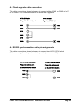
3.7 RS232 control ........................................................................................ 28
3.8 Cascading LINDY CPU Switch Multiscreens ........................................ 28
3.9 Synchronising LINDY CPU Switch Multiscreens for multiple video
head applications .................................................................................. 31
4. LINDY CPU Switch Multiscreen configuration options .............. 33
4.1 Screen saver time delay ....................................................................... 33
4.2 Autoscan lock on mode and delay time ................................................ 33
4.3 Mouse mode and mouse switching of channels .................................... 34
4.4 Keyboard hotkey combination ............................................................... 35
4.5 Cycling between all channels or just the active channels ..................... 36
4.6 Firmware functions (version query, mouse restore and reset) .............. 36
4.7 Setting a security password .................................................................. 37
4.8 Cascade query code ............................................................................. 38
4.9 Resolving slow mouse problems .......................................................... 38
4.10 Exit configure mode ............................................................................ 39
Appendices
A - Cable and connector specifications................................................................ 40
B - Problem solving .............................................................................................. 45
LINDY CPU Switch Multiscreen Installation and Use
Page 5
1. Introduction
Thank you for purchasing the LINDY CPU Switch Multiscreen. Your LINDY CPU
Switch Multiscreen is a high performance Keyboard, Video monitor and Mouse
(KVM) sharing device which supports a wide range of PC hardware and software
platforms. The Multiscreen is a new concept in KVM switches and enables you to
benefit from all the convenience of the proven LINDY CPU Switches whilst taking
advantage of the multiple monitor facilities available on many modern computers.
Computers fitted with multiple video cards are becoming more common as operating
systems have developed to make use of the extended video "real estate" offered by
multiple monitors. The increased display area enables more information to be
presented to the user without reducing the resolution. The Multiscreen enables
several computers equipped with these multiple video facilities to be controlled from
a keyboard, mouse and an array of monitors. All the monitors and the keyboard and
mouse are switched together from one computer to the next giving you full control of
the wider picture.
1.1 Key features
Control several multi-video enabled PCs with from a single keyboard, mouse and
a bank of monitors.
Dual and quad video head models available with two or four computer ports.
Two or more Multiscreens may be synchronously switched by linking their options
ports.
Switch 4,8,12 or 16 monitors together by synchronising Multiscreens.
Excellent for banking, security and engineering applications.
Supports high bandwidth monitors at resolutions up to 1920 x 1440 with an
excellent video transfer characteristic - high bandwidth and low distortion.
Continuous keyboard and mouse emulation on all ports ensures problem free
computer bootup.
Interface powered operation – LINDY CPU Switch Multiscreen draws its power
from the connected computers for maximum convenience.
LINDY CPU Switch Multiscreen Installation and Use
Page 6
Intelligent switching feature enables users to switch between all ports or just the
active ports.
Mixed AT/PS2 keyboards and PS2/RS232 mice supported as standard.
Flash upgradeable - LINDY CPU Switch Multiscreen’s firmware may be upgraded
by connecting a computer’s serial port and running a download program.
Can be cascaded to provide a video switching network.
Video channels support Display Data Channel (DDC/DDC1/DDC2) signalling.
Password security prevents unauthorised use.
User options stored in EEPROM memory.
Optional remote control module for convenient operation.
Channel switching by front panel key, keyboard hotkey, or 3 button mouse.
Automatically restores keyboard and mouse states when channel changed.
Supports keyboard modes 1,2 and 3 and mouse prompt and stream modes for
maximum compatibility.
Can be controlled remotely via an RS232 serial port.
Includes screen saver, auto-scan and variable hotkey options.
Supports Microsoft IntelliMouse, IntelliMouse Explorer and other common wheel
mice.
Mouse restoration functions to enable ‘hot plugging’ of certain systems.
Keyboard, mouse and LINDY CPU Switch Multiscreen resets may be performed
without disconnecting devices.
Supports IBM ThinkPad ‘Y’ cables.
Power and activity indication confirm correct operation.
Standard cable connections make installation easy and inexpensive.
All ports are active simultaneously – all PCs may all be booted at the same time.
Robust metal case ensures good shielding and video quality.
Supports desktop and laptop PCs, RS6000s, DEC Alphas, and Silicon Graphics
computers .
LINDY CPU Switch Multiscreen Installation and Use
Page 7
Supports very wide range of software including Windows 3.X, WFWG, 95, 98,
2000, NT,ME, XP, DOS, Unix, Linux, NetWare, OS/2, BSD etc.
Supports the additional shortcut, web access and media control keys found on
extended keyboards.
May be connected to LINDY CPU Switch Smart products for synchronised
switching applications.
Optional power adapter can be used for ‘video only’ or cascade applications.
1.2 Package contents
LINDY CPU Switch Multiscreen.
This installation guide.
(Please note that a power adapter is NOT required for most applications and so is
not included. This may be purchased separately if required).
1.3 Remote controller contents (part code: 32255)
Remote control module.
Velcro strip for mounting remote controller.
LINDY CPU Switch Multiscreen Installation and Use
Page 8
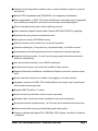
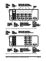
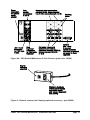
1.4 Product information
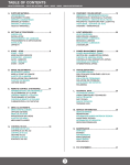
Figure 1 - LINDY CPU Switch Multiscreen front view
Figure 2a - CPU Switch Multiscreen 4 Port 4 Screen (part code: 32349)
LINDY CPU Switch Multiscreen Installation and Use
Page 9
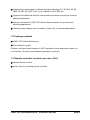
Figure 2b - CPU Switch Multiscreen 4 Port 2 Screen (part code: 32347)
Figure 2c - CPU Switch Multiscreen 2 Port 4 Screen (part code: 32348)
LINDY CPU Switch Multiscreen Installation and Use
Page 10
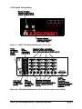
Figure 2d - CPU Switch Multiscreen 2 Port 2 Screen (part code: 32346)
Figure 3 - Remote control pad / display (optional accessory - part 32255)
LINDY CPU Switch Multiscreen Installation and Use
Page 11
2. Installation
2.1 What you will need
Cables to connect the LINDY CPU Switch Multiscreen to each of your PC
keyboard, video and mouse ports. Cable specifications are given in appendix A. For
convenience we suggest that you connect your keyboard, mouse and first video port
using a LINDY 3-in-1 combination cable. Additional video ports may then be
connected using video-only cables.
Monitors with standard VGA/SVGA (15 pin) connector that will work when
connected directly to each of your PCs. LINDY CPU Switch Multiscreen supports
low and high resolution monitors.
A standard AT or PS/2 style keyboard. If you are using an AT keyboard with a 5
pin connector you may connect this to the LINDY CPU Switch Multiscreen using a
standard AT to PS/2 keyboard adapter.
A PS/2 style two or three button Microsoft or Logitech compatible mouse or a
Microsoft IntelliMouse / IntelliMouse Explorer compatible mouse. If you wish to use
the mouse to switch the LINDY CPU Switch Multiscreen’s channel then you will
need a three button mouse or an IntelliMouse.
(The LINDY CPU Switch Multiscreen supports ‘Internet Mice’ that are compatible
with the Microsoft IntelliMouse. These are fitted with a wheel or other scroll control
and sometimes have additional buttons. Examples are: Microsoft IntelliMouse,
Logitech Pilot Mouse+, Logitech MouseMan+, Genius NetMouse and Genius
NetMouse Pro.)
A suitable mouse driver for your PCs. Supported types are:
- PS/2 or RS232 two button mouse driver (any manufacturer).
- Microsoft mouse driver (including IntelliMouse).
- Logitech mouse driver (including two button, three button and wheel mouse).
Use of PS/2 and RS232 style mice with the LINDY CPU Switch Multiscreen - All
of the mouse connections from LINDY CPU Switch Multiscreen to PCs support
either a PS/2 or an RS232 mouse. LINDY CPU Switch Multiscreen automatically
converts from the PS/2 mouse commands to RS232 serial mouse commands. Serial
mice types are selected by using an adapter as described in Appendix A. The
LINDY CPU Switch Multiscreen Installation and Use
Page 12
LINDY CPU Switch Multiscreen will operate without a mouse connected if you do
not wish to use one.
2.2 Mounting the LINDY CPU Switch Multiscreen
The LINDY CPU Switch Multiscreen has been designed for use on a desktop or
shelf in close proximity to the user’s monitor and peripherals. The optional remote
controller may be used if you wish to locate the LINDY CPU Switch Multiscreen on a
desk or shelf that is some distance from the monitor and peripherals.
2.3 Connecting your devices
Ensure that the optional power adapter is disconnected from the LINDY CPU Switch
Multiscreen and that all the devices which are to be attached are switched off.
Connect the shared keyboard, PS/2 mouse and monitors to the connectors at the
rear of the LINDY CPU Switch Multiscreen (see figs 1, 2 and 3). Next, connect each
computer system unit in turn with the keyboard cable, mouse cable and video
cables. For the keyboard, mouse and first video port, LINDY 3-in-1
keyboard/video/mouse cables are recommended for maximum convenience. Any
unused computer connections can be left unconnected. To connect computers with
serial mouse connections and AT style keyboard connections use the adapters
specified in appendix A. If you have an existing 6-pin mini-DIN to 9-pin serial
adapter that came with a mouse it may not be suitable for use with the LINDY as
there are several different standard wiring configurations for these adapters.
The LINDY CPU Switch Multiscreen is now ready for use and will start to operate as
soon as one of the attached PCs is powered on. If you are connecting to PCs using
cables that are longer than 5 metres or are cascading the LINDY CPU Switch
Multiscreen to another LINDY CPU Switch Multiscreen you will need to use the
LINDY CPU Switch Multiscreen Installation and Use
Page 13
optional power adapter. When using the optional power adapter, ensure that it is
connected to the mains and powering the LINDY CPU Switch Multiscreen before
you switch on the connected computers. Failure to switch the LINDY CPU Switch
Multiscreen and computers on in the correct order can lead to the mouse and/or
keyboard not being recognised by the computers when they are switched on.
2.4 ‘Interface powered’ operation without the optional power
adapter
The LINDY CPU Switch Multiscreen draws its power from the connected computers
via the keyboard cables. A single keyboard connection is normally sufficient to
power the LINDY CPU Switch Multiscreen provided that the cable is no longer than
5 metres. If more than one computer is connected then the power will be intelligently
drawn from all computers. Cables longer than 5 metres may be used provided that
the LINDY CPU Switch Multiscreen is already powered by another connected
computer or the optional power adapter. If you are cascading the LINDY CPU
Switch Multiscreen to another LINDY CPU Switch Multiscreen then a power adapter
must be connected to all LINDY CPU Switch Multiscreens.
2.5 Configuring your PCs
Configure your PC in the same way that you would if your keyboard, mouse and
monitor were all connected directly to your PC. LINDY CPU Switch Multiscreen
emulates Microsoft compatible serial, IntelliMouse, IntelliMouse Explorer and PS/2
mice, so ensure that your PC software is configured for a Microsoft mouse of the
correct type. Refer to the list of supported drivers in section 2.1.
2.6 Configuring the LINDY CPU Switch Multiscreen
The LINDY CPU Switch Multiscreen is supplied pre-configured with factory defaults
which are suitable for most applications. There are a number of more advanced
options which can be set by the user. These are stored in the LINDY CPU Switch
Multiscreen’s EEPROM memory and are retained when the power is disconnected.
The options may be changed whilst the LINDY CPU Switch Multiscreen is in
configure mode. You may enter configure mode at initial power on or whilst the
LINDY CPU Switch Multiscreen is running:
LINDY CPU Switch Multiscreen Installation and Use
Page 14
To enter configure mode at power on:
Switch off all the attached PCs and the LINDY CPU Switch Multiscreen. Hold down
the front panel key whilst powering on the LINDY CPU Switch Multiscreen.
Remember that the LINDY CPU Switch Multiscreen draws its power from any
attached PC via the keyboard cable and so will power itself on when the attached
PC is switched on or when the optional power adapter is connected. Do not release
the key until the LINDY CPU Switch Multiscreen displays ’C’ to show that it has
entered configure mode.
To enter configure mode whilst the LINDY CPU Switch Multiscreen is running:
Hold down the front panel key for 5 seconds until the front panel display shows ‘C’.
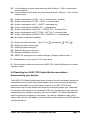
In configure mode, options are entered by typing a letter followed by a number
followed by (return). Use ESC to abort the entry of an option. The LINDY CPU
Switch Multiscreen will remain in configure mode until you type 'E' (return).
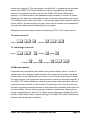
For example: to set hotkey option 2 type the following at the 'C' prompt
(at LINDY CPU Switch Multiscreen 'C' prompt)
To exit configure mode type:
+
I
(
I
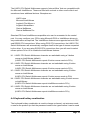
2.7 Summary of LINDY CPU Switch Multiscreen configuration
options
Full details of each of the configuration options and their uses are given in section 4.
B1 - screen saver disabled (default)
B2 - Blank screen after 1 minute of inactivity
B3 - Blank screen after 2 minutes of inactivity
B4 - Blank screen after 4 minutes of inactivity
B5 - Blank screen after 8 minutes of inactivity
B6 - Blank screen after 12 minutes of inactivity
B7 - Blank screen after 16 minutes of inactivity
B8 - Blank screen after 20 minutes of inactivity
LINDY CPU Switch Multiscreen Installation and Use
Page 15
L1 - CPU Switch Multiscreen locks on to active ports only during autoscanning
(default)
L2 - CPU Switch Multiscreen locks on to every port during autoscanning
L3 - CPU Switch powers on in autoscan mode and locks on to active ports only
L4 - CPU Switch Multiscreen powers on in autoscan mode and locks on to all ports
L5 – Allow the mouse to run at any speed (default)
L6 – Don't allow the mouse to run at very slow speeds
L7 - Cascade query code = AD (default)
L8 - Cascade query code = EF
T1 - 2 seconds autoscan delay time before switching to next port (default)
T2 - 5 seconds autoscan delay time before switching to next port
T3 - 7 seconds autoscan delay time before switching to next port
T4 - 10 seconds autoscan delay time before switching to next port
T5 - 15 seconds autoscan delay time before switching to next port
T6 - 20 seconds autoscan delay time before switching to next port
T7 - 30 seconds autoscan delay time before switching to next port
T8 - 60 seconds autoscan delay time before switching to next port
U1 - LINDY CPU Switch Multiscreen channels are switchable using a 3 button
mouse or IntelliMouse (default)
(LINDY CPU Switch Multiscreen reports 2 button mouse mode to PCs)
U2 - LINDY CPU Switch Multiscreen channels are not switchable using 3 button
mouse or IntelliMouse
(LINDY CPU Switch Multiscreen reports 2 button mouse mode to PCs)
U3 - LINDY CPU Switch Multiscreen channels are not switchable using 3 button
mouse or IntelliMouse
(LINDY CPU Switch Multiscreen reports 3 button mouse mode to PCs)
U4 - LINDY CPU Switch Multiscreen channels are switchable using 3 button mouse
or IntelliMouse
(LINDY CPU Switch Multiscreen reports IntelliMouse mode to PCs)
U5 - LINDY CPU Switch Multiscreen channels are not switchable using 3 button
mouse or IntelliMouse
(LINDY CPU Switch Multiscreen reports IntelliMouse mode to PCs)
LINDY CPU Switch Multiscreen Installation and Use
Page 16
U7 – Cycle between all ports when switching with ‘Hotkeys + Tab’ or three button
mouse (default)
U8 – Cycle between active ports only when switching with ‘Hotkeys + Tab’ or three
button mouse
H1 - Hotkey combination is CTRL + ALT + command key (default)
H2 - Hotkey combination is CTRL + SHIFT + command key
H3 - Hotkey combination is ALT + SHIFT + command key
H4 - Hotkey combination is RIGHT ALT + command key
H5 - Hotkey combination is LEFT ALT + RIGHT ALT + command key
H6 - Hotkey combination is LEFT CTRL + LEFT ALT + command key
H7 - Hotkey combination is RIGHT CTRL + RIGHT ALT + command key
H8 - No hotkey combination enabled
F1 - Display firmware first digit (Note: F1 is ) followed by NOT O)
F2 - Display firmware second digit
F3 - Display firmware third digit
F5 - Restore PS/2 mouse function
F6 - Restore IntelliMouse function
F8 - RESET all configurations to default settings. (Display confirms with 'r').
P - Sets password - see section 4.6 for instructions.
E - Exits configure mode and returns the LINDY CPU Switch Multiscreen to normal
operation mode.
2.8 Resetting the LINDY CPU Switch Multiscreen without
disconnecting your devices
The LINDY CPU Switch Multiscreen draws its power from the connected computers
and therefore may only be fully powered down when all the connected computers
have been switched off or disconnected. However, the LINDY CPU Switch
Multiscreen may be reset without disconnecting or powering down your computers
by using the reset switch on the underside of the unit. Performing a reset using this
switch performs a complete hardware reset on the LINDY CPU Switch Multiscreen
and is equivalent to switching off the power. To perform a hardware reset, move
option switch 8 to the ON position (halt and reset) and then back to the OFF position
(normal operation).
LINDY CPU Switch Multiscreen Installation and Use
Page 17
2.9 Other useful installation information
PC boot up sequence - When your PCs are powered on they communicate with
any attached keyboards and mice and setup parameters required by the particular
operating system. It is necessary for the LINDY CPU Switch Multiscreen to be
attached and powered on during this sequence so that it can give the required
responses and keep track of all the modes and settings requested by each of the
connected PCs.
Mouse characteristics - do not unplug a PS/2 mouse connection from a PC whilst
the PC is on. Due to the design of PS/2 mice communications the mouse function on
the PC will be lost and you will have to re-boot the PC to regain normal operation.
Unplugging the mouse from the LINDY CPU Switch Multiscreen will also cause it to
stop operating when it is plugged back in. RS232 mice can usually be unplugged
and plugged back in provided that a mouse was connected when the operating
system initially booted. The LINDY CPU Switch Multiscreen is fitted with a PS/2
mouse recovery system which allows you to disconnect and re-connect the shared
mouse without powering down the system (although this is generally not advisable) see section 2.10 for details.
Keyboard and mouse mode switching - The LINDY CPU Switch Multiscreen
keeps a log of the keyboard and mouse mode and resolution settings requested by
each of the connected PCs. These settings are automatically restored to the shared
keyboard and mouse when the LINDY CPU Switch Multiscreen channel is switched
thus ensuring maximum software compatibility. The keyboard num, caps and scroll
lock states are an obvious example of this process.
2.10 Re-enabling a disconnected PS/2 mouse
If you disconnect the shared PS/2 mouse from the LINDY CPU Switch Multiscreen
by accident during operation then the mouse operation will be lost when the mouse
is plugged back in. To avoid having to reboot the entire system in this situation the
LINDY CPU Switch Multiscreen is fitted with an automatic mouse recovery system.
With the PS/2 mouse disconnected, change the channel using the keypad or
keyboard hotkeys. The LINDY CPU Switch Multiscreen detects that the mouse has
been disconnected and triggers the automatic recovery system. Plug in the PS/2
mouse and the LINDY CPU Switch Multiscreen will re-initialise it.
Alternatively you can reset the keyboards and mice by holding down the front panel
LINDY CPU Switch Multiscreen Installation and Use
Page 18
key for 5 seconds. When the character ‘C’ is displayed on the front of the LINDY
CPU Switch Multiscreen, press the front panel key again. A complete power off reset
of the connected keyboards and mice will then be performed. This function only
resets the shared keyboard and mice that are plugged into the control port. It does
not affect the status of any of the other ports on the switch or the CPU connections.
2.11 Hot plugging the LINDY CPU Switch Multiscreen into running
systems and re-enabling disconnected CPU PS/2 mouse
connections
It is advisable to switch off the systems that are going to be connected to the LINDY
CPU Switch Multiscreen before installation. However, if this is not possible then
most systems can be hot plugged by using the LINDY CPU Switch Multiscreen’s
mouse restoration functions. The keyboard connection will normally restore itself
automatically.
On many PCs, mouse movement will be lost if the PS/2 mouse is unplugged and
plugged back in whilst the PC is running. Mouse movement can then only be
restored by rebooting the PC. This is because the mouse drivers only setup and
enable the mouse when the PC is initially booted.
If you have switched off your LINDY CPU Switch Multiscreen or you are attempting
to ‘hot plug’ it into a system that is already running, you may be able to restore lost
mouse movement using the LINDY CPU Switch Multiscreen's mouse restoration
functions.
Mouse restoration functions should be used with care as unpredictable results
may occur if the wrong mouse type is selected. If in doubt restore the mouse
by powering down the PC normally.
Standard PS/2 mouse data uses a different data format to IntelliMouse data and so
two reset functions are provided on the LINDY CPU Switch Multiscreen. The type of
data format expected by the PC depends upon the driver and the type of mouse that
was connected when the driver was booted. The following table may be used as a
guide.
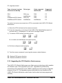
Note that the mouse reset functions predict the likely mouse resolution settings but
may not restore the speed or sensitivity of the mouse exactly as they were when the
LINDY CPU Switch Multiscreen Installation and Use
Page 19
PC originally booted.
Type of mouse / system
Connected at bootup
Driver type
Likely expected
data format
Suggested
restoration
PS/2
PS/2
IntelliMouse/CPU Switch
IntelliMouse/CPU Switch
PS/2 only
IntelliMouse
PS/2 only
IntelliMouse
PS/2
PS/2
PS/2
IntelliMouse
F5
F5
F5
F6
To restore lost mouse movement on a CPU connected to the LINDY CPU Switch
Multiscreen:
1) Select the CPU that has lost its mouse movement
2) Press the select key on the front of the LINDY CPU Switch Multiscreen for 5
seconds until ‘C’ is displayed. You are now in configure mode.
3) To restore a PS/2 mouse connection press
) I
Or, to restore an IntelliMouse connection press
) I
4) Exit from configure mode by typing
(I
5) Test the mouse movement by moving the mouse a short distance.
F5 - Restore PS/2 mouse function
F6 - Restore IntelliMouse function
2.12 Upgrading the CPU Switch’s flash memory
The LINDY CPU Switch Multiscreen uses flash memory technology which enables
the firmware code to be upgraded by the user. Upgrades are performed by
connecting a PC's serial port to the LINDY's options port and running an upgrade
program on the PC. This upgrade program downloads the new firmware to the
LINDY CPU Switch Multiscreen and checks that the data has been programmed
correctly.
LINDY CPU Switch Multiscreen Installation and Use
Page 20
To perform a firmware upgrade on your LINDY CPU Switch Multiscreen you will
need a suitable serial upgrade cable and an IBM PC compatible computer with an
RS232 serial port and an operating system that supports DOS. Upgrade cables may
be purchased for LINDY Technology or may be made using the wiring specification
given in Appendix A4. You will also need to download the latest version of the
LINDY CPU Switch Multiscreen firmware which is available free of charge at
www.lindy.com.
To perform a flash upgrade on the LINDY CPU Switch Multiscreen:
Step 1 - Connect your computer to the LINDY CPU Switch Multiscreen
Connect your computer’s serial port to the LINDY CPU Switch Multiscreen’s options
port (labelled OPTIONS/FLASH).
Step 2 - Select flash upgrade mode using option switch 7
Move option switch 7 on the underside of the LINDY CPU Switch Multiscreen to the
ON position.
Step 3 - Reset the LINDY CPU Switch Multiscreen
Reset the LINDY CPU Switch Multiscreen by moving option switch 8 to the ON
position (halt and reset) and then back to the OFF position (normal operation).
Alternatively you may reset the LINDY CPU Switch Multiscreen by powering off all
the attached computers and removing the optional power adapter.
Step 4 - Ensure that the LINDY CPU Switch Multiscreen is powered on
Ensure that the LINDY CPU Switch Multiscreen is powered on. It is normally
possible to upgrade the LINDY CPU Switch Multiscreen when it is powered from a
single computer, however it is good practice to ensure that there is the maximum
possible power availability during flash upgrades and so if possible ensure that all
the computers are powered on. The upgrade program monitors the LINDY CPU
Switch Multiscreen’s voltage and will not allow an upgrade to be performed if the
voltage is insufficient.
The display should now show:
LINDY CPU Switch Multiscreen Installation and Use
Page 21
Step 5 - Run the upgrade program
The latest version of the LINDY CPU Switch Multiscreen firmware is available from
the LINDY Technology website at www.lindy.com. The CPU Switch
Multiscreen uses the same firmware as the CPU Switch Smart
product. The program and data files are supplied as a pair e.g.
CPUSS129.EXE
CPUSS129.HEX
and should be downloaded to the same directory on your PC. Run the file
CPUSSxxx.EXE (e.g. CPUSS129.EXE) and follow the on-screen instructions. During
the upgrade the display will show an upper case U and the dot will flash to show that
the upgrade is in progress.
The display will again show a lower case U when the download is complete. Move
option switch 7 to the OFF position to exit upgrade mode and start normal operation.
You may check the new firmware version by entering configure mode and using the
firmware version query function.
Some useful issues to bear in mind when performing flash upgrades
The upgrade program rewrites the LINDY CPU Switch Multiscreen’s firmware code.
If the upgrade process is interrupted then the LINDY CPU Switch Multiscreen will
have invalid code and will not be able to operate. It is therefore good practice to
ensure that the upgrade process is always fully completed. A partial or failed
upgrade may be rectified by performing another upgrade. If the upgrade process is
interrupted accidentally then you should immediately repeat the upgrade process
LINDY CPU Switch Multiscreen Installation and Use
Page 22
without moving switch 7 from the flash upgrade (ON) position. Switch 7 forces the
LINDY CPU Switch Multiscreen into flash upgrade mode and prevents the upgraded
code from being run. Running faulty or partially upgraded code may have
unpredictable results and may damage your LINDY CPU Switch Multiscreen or
computing equipment. For obvious reasons, the code that the LINDY CPU Switch
Multiscreen uses to perform upgrades is not itself upgradeable - a common problem
on some flash upgradeable products that could effectively be destroyed by a partial
upgrade!
WARNING - Running faulty or partially upgraded code may have unpredictable
results and may damage your LINDY CPU Switch Multiscreen or computing
equipment.
LINDY CPU Switch Multiscreen Installation and Use
Page 23
3. Using the LINDY CPU Switch Multiscreen
This section explains the general operation of the LINDY CPU Switch Multiscreen.
We recommend that you read this section before starting to use the product.
3.1 Power on status
At power on the LINDY CPU Switch Multiscreen selects computer 1 and displays ’1’.
If a password has been set then ‘P’ will be displayed and the LINDY CPU Switch
Multiscreen will remain locked until a valid password is entered.
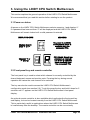
3.2 Front panel key and remote controller
The front panel key is used to select which channel is currently controlled by the
shared keyboard, mouse and monitor ports. Pressing the key during normal
operation will cause the next channel to be selected.
The key can also be used to access the LINDY CPU Switch Multiscreen’s
configuration mode (see section 2.6). To do this press the key and hold it down for 5
seconds until ‘C’ appears on the LINDY CPU Switch Multiscreen’s front panel
display.
An optional remote controller is also available which replicates the front panel key
and display, but can be located remotely from the LINDY CPU Switch Multiscreen.
This is particularly useful in applications where the LINDY CPU Switch Multiscreen
is located away from the desktop. The remote controller can be conveniently
LINDY CPU Switch Multiscreen Installation and Use
Page 24
attached to your keyboard with a couple of Velcro strips to give instant channel
information and key control.
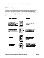
3.3 Status display
The status display usually shows the currently selected port. If autoscan mode is
selected, the segments will illuminate in sequence in a clockwise direction
interspersed with a display of the currently selected channel. If LINDY CPU Switch
Multiscreen has been locked, ‘P’ will be displayed until a valid password has been
typed to unlock the unit. Data flow from the mouse or keyboard causes the dot to
flash.
LINDY CPU Switch Multiscreen Installation and Use
Page 25
3.4 Switching operation
When you select a port, your keyboard and mouse will control the computer that is
connected to that port and the video feeds from that that computer will be displayed
on the monitors. For example, if you select channel 2 then the video signal arriving
at port 2A will be sent to the monitor that is attached to port A. Video arriving at
ports 2B, 2C and 2D will be displayed on the monitors attached to ports B, C and D
respectively.
3.5 Keyboard hotkey control
LINDY CPU Switch Multiscreen can be conveniently controlled by selecting channel,
autoscan mode or security locking from the keyboard. All of the hotkey control
commands are invoked by holding down the two hotkeys and then pressing a
command key. By default, the two hotkeys are ‘CTRL’ and ‘ALT’, although other
combinations can be selected by reconfiguring the hotkeys (see section 4.4). Once
the hotkey command has been activated you will need to release the hotkeys and
the command key before a new hotkey command is accepted by the LINDY CPU
Switch Multiscreen. HOTKEYs + TAB is an exception and this allows you to 'tab
through' the ports by holding down the hotkeys and repeatedly pressing TAB.
The hotkey command are summarised below (note that the numbers on the numeric
keypad do not form part of a valid hotkey) :
‘HOTKEYs’ and ‘1’ - selects channel 1
‘HOTKEYs’ and ‘2’ - selects channel 2
‘HOTKEYs’ and ‘3’ - selects channel 3
‘HOTKEYs’ and ‘4’ - selects channel 4
‘HOTKEYs’ and ‘TAB’ - selects the next channel
‘HOTKEYs’ and ‘A’ - selects autoscan mode where each channel is displayed for
the selected time (see section 4.2). To cancel autoscan mode simply select any
fixed channel either by hotkey or using the LINDY CPU Switch Multiscreen button.
‘HOTKEYs’ and ‘0’ – switches off the video signal and displays 0. This will cause
some monitors to go into standby mode or switch off. The video signal can be reenabled by selecting a channel.
‘HOTKEYs’ and ‘L’ - disables the LINDY CPU Switch Multiscreen’s keyboard and
LINDY CPU Switch Multiscreen Installation and Use
Page 26
mouse and displays 0. The video signal is switched off. If a password has not been
set then the LINDY CPU Switch Multiscreen can be re-enabled by selecting a
channel. If a password has been set then the LINDY CPU Switch Multiscreen
displays ’P’ to indicate that a valid password must be entered to unlock the switch.
Simply type the same key combination as was set during configuration (see section
4.7) followed by the (return) key. Note - if anyone has typed at the keyboard whilst in
secure mode, it will be necessary to type (return) first to clear the invalid password,
then type the valid password followed by (return) again.
Examples of common hotkey sequences (assuming CTRL + ALT hotkey option):
To select channel 2:
press
ED
release
ED
To ’tab through’ channels:
press
EDY release Y pressY
release
Y press Y release YED
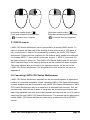
3.6 Mouse control
Computers may conveniently be selected using a three button mouse. In order to
switch to the next computer simply hold down the central mouse button (the wheel
mouse button on an IntelliMouse) and click on the left hand mouse button to select
the next computer or the right hand mouse button to select the previous computer. If
the LINDY CPU Switch Multiscreen has been set to scan active ports then the next
or previous active channel will be selected. If it has been set to scan all ports then
the next or previous numerical channel in sequence will be selected (see section 4.5
for more details). Mouse switching may be enabled or disabled by setting options
during configuration (see section 4.3). When mouse switching is disabled the third
button or wheel button state is ‘passed through’ the LINDY CPU Switch Multiscreen
and seen by the application software.
LINDY CPU Switch Multiscreen Installation and Use
Page 27
)
Hold down centre button (
Press and release left hand button
(
) to select next computer
Hold down centre button (
)
Press and release right hand button
(
) to select previous computer
3.7 RS232 control
LINDY CPU Switch Multiscreen can be controlled by a remote RS232 device. To
select a channel the data rate of the sending device must be set to 1200 baud, 8
bits, no parity and 1 stop bit. No handshaking is used by the LINDY CPU Switch
Multiscreen. Simply send the character for the channel which needs to be selected,
for example ASCII ‘1’ (hex code 31) will select channel 1, ASCII ‘2’ (hex code 32)
will select channel 2 and so on. The LINDY CPU Switch Multiscreen will echo the
ASCII character back to the sending device when the channel has been changed.
The serial interface pins are found on the options connector on the rear of the
LINDY CPU Switch Multiscreen. Pin assignments for this connector are given in
appendix A
3.8 Cascading LINDY CPU Switch Multiscreens
LINDY CPU Switch Multiscreen switches can be connected together to expand the
number of connected computers. When cascading LINDY CPU Switch Multiscreens
a power adapter must be connected to each LINDY CPU Switch Multiscreen. LINDY
CPU Switch Multiscreens can be connected in a cascaded tree structure. This can
be particularly useful where clusters of computers are located some distance from
each other because each unit acts as data booster and can each be up to 30 metres
away from the next LINDY CPU Switch Multiscreen. The channel can be selected on
remote LINDY CPU Switch Multiscreen units using an extension of the HOTKEY
control .
LINDY CPU Switch Multiscreen Installation and Use
Page 28
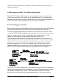
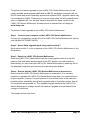
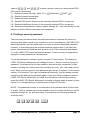
For example, consider a situation where two LINDY CPU Switch Multiscreen units
are connected together as shown below. To connect to the computer attached to
port 3 on LINDY CPU Switch Multiscreen B the user would hold down the hotkey
keys then press ‘2’ followed by ‘3’, whilst keeping the hotkey keys pressed. This will
have the effect of connecting to port ‘3’ of the LINDY CPU Switch Multiscreen which
is connected into port ‘2’ of the first LINDY CPU Switch Multiscreen unit A.
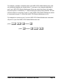
For example to connect to port 3 on the LINDY CPU Switch Multiscreen cascaded
off port 2 of your first LINDY CPU Switch Multiscreen use:
press
EDrelease press
release ED
LINDY CPU Switch Multiscreen Installation and Use
Page 29
A typical cascade of two LINDY CPU Switch Multiscreens
LINDY CPU Switch Multiscreen Installation and Use
Page 30
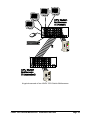
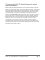
3.9 Synchronising LINDY CPU Switch Multiscreens for multiple
video head applications
Multiple LINDY CPU Switch Multiscreens may be connected together so that they
operate in a synchronised manner. Synchronised operation is useful for applications
that require multiple video signals to be switched together. This type of operation is
usually required where each computer is fitted with multiple video cards or video
cards with multiple video heads. Such configurations are typically required in
banking and engineering applications where greater video ’real estate’ is required.
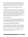
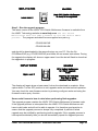
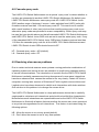
Whenever the LINDY CPU Switch Multiscreen’s channel is switched it sends an
RS232 command out on its serial interface. The LINDY CPU Switch Multiscreen
switches its channel if it receives the same command on its serial interface.
Consequently, by linking the serial interfaces a master unit may be made to
automatically switch a daisy chain of slaved units as shown in the diagram below.
The slave units will require the optional power adapters because they cannot draw
their power from the video link alone.
LINDY CPU Switch Multiscreen Installation and Use
Page 31
Synchronised LINDY CPU Switch Multiscreens used to
switch eight video channels together
LINDY CPU Switch Multiscreen Installation and Use
Page 32
4. LINDY CPU Switch Multiscreen configuration
options
All the options described in this section are entered in LINDY CPU Switch
Multiscreen configure mode - see section 2.6 for instructions on entering configure
mode.
4.1 Screen saver time delay
LINDY CPU Switch Multiscreen contains a programmable screen saver which will
blank the display after the set time delay with no keyboard or mouse activity. Simply
typing at the keyboard or moving the mouse will re-enable the display. The display
will flash whilst the LINDY CPU Switch Multiscreen is in screen save mode.
B1 - screen saver disabled (default)
B2 - Blank screen after 1 minute of inactivity
B3 - Blank screen after 2 minutes of inactivity
B4 - Blank screen after 4 minutes of inactivity
B5 - Blank screen after 8 minutes of inactivity
B6 - Blank screen after 12 minutes of inactivity
B7 - Blank screen after 16 minutes of inactivity
B8 - Blank screen after 20 minutes of inactivity
4.2 Autoscan ‘lock on’ mode and delay time
LINDY CPU Switch Multiscreen can be set to select each channel in turn for a
period of time set by the autoscan delay time. Autoscan mode is entered by typing
the hotkey keys together with ‘A’. By default, only those channels which have a
powered up computer connected to them will be scanned. Sometimes it may be
desirable to scan all channels, even if the attached computer is switched off (this will
simply show a blank screen when it is selected). All the LINDY CPU Switch
Multiscreen’s ports will be scanned if option L2 is selected. Some applications may
also require the LINDY CPU Switch Multiscreen to power on in autoscan mode. This
feature can be selected using the L3 or L4 options.
LINDY CPU Switch Multiscreen Installation and Use
Page 33
L1 - CPU Switch Multiscreen only locks on to active ports during autoscanning
(default)
L2 - CPU Switch Multiscreen locks on to every port in turn during autoscanning
L3 - CPU Switch powers on in autoscan mode and locks on to active ports only
L4 - CPU Switch Multiscreen powers on in autoscan mode and locks on to all ports
T1 - 2 seconds autoscan delay time before switching to next port (default)
T2 - 5 seconds autoscan delay time before switching to next port
T3 - 7 seconds autoscan delay time before switching to next port
T4 - 10 seconds autoscan delay time before switching to next port
T5 - 15 seconds autoscan delay time before switching to next port
T6 - 20 seconds autoscan delay time before switching to next port
T7 - 30 seconds autoscan delay time before switching to next port
T8 - 60 seconds autoscan delay time before switching to next port
Note: Autoscan mode is ended simply by selecting a fixed channel using the
keypad, the keyboard hotkeys or the mouse.
WARNING - Many modern monitors are fitted with automatic power save relays
and will switch off after a few seconds if connected to an inactive PC. If you
are using such a monitor you must not use the L2 feature. Constant switching
on and off of your monitor’s relay will eventually damage your monitor.
4.3 Mouse mode and mouse switching of channels
A three button PS/2 mouse or an IntelliMouse can be used to switch channels on the
LINDY CPU Switch Multiscreen. To switch to the next channel, the user simply holds
down the central button or wheel button and presses the left or right hand button to
change the channel (see section 3.6). If the user does not wish to take advantage of
this feature, it can be disabled by selecting U2, U3 or U5. If the third button is being
used to switch the LINDY CPU Switch Multiscreen then it is not available for use
with PC software although the function of an IntelliMouse wheel is not affected.
Consequently in modes U1, U2 and U4 the LINDY CPU Switch Multiscreen reports
to the PCs that a 2 button mouse is connected. If you wish to use the full function of
a 3 button mouse or IntelliMouse for your PC software then you should select
options U3 or U5.
LINDY CPU Switch Multiscreen Installation and Use
Page 34
The LINDY CPU Switch Multiscreen supports ‘Internet Mice’ that are compatible with
the Microsoft IntelliMouse. These are fitted with a wheel or other scroll control and
sometimes have additional buttons. Examples are:
LINDY mice
Microsoft IntelliMouse
Logitech Pilot Mouse +
Logitech MouseMan+
Genius NetMouse
Genius NetMouse Pro
Standard PS/2 and IntelliMouse compatible mice can be connected to the control
port. You may configure your CPUs using Microsoft PS/2 or IntelliMouse drivers in
any combination as required. The IntelliMouse features are supported on both PS/2
and RS232 CPU connections. When using PS/2 CPU connections, the LINDY CPU
Switch Multiscreen will automatically configure itself to the type of mouse requested
by the driver. If you are using RS232 CPU connections then you will need to select
mouse options U4 or U5 to enable the IntelliMouse features.
U1 - LINDY CPU Switch Multiscreen channels are switchable using a 3 button
mouse or IntelliMouse (default)
(LINDY CPU Switch Multiscreen reports 2 button mouse mode to PCs)
U2 - LINDY CPU Switch Multiscreen channels are not switchable using 3 button
mouse or IntelliMouse
(LINDY CPU Switch Multiscreen reports 2 button mouse mode to PCs)
U3 - LINDY CPU Switch Multiscreen channels are not switchable using 3 button
mouse or IntelliMouse
(LINDY CPU Switch Multiscreen reports 3 button mouse mode to PCs)
U4 - LINDY CPU Switch Multiscreen channels are switchable using 3 button mouse
or IntelliMouse
(LINDY CPU Switch Multiscreen reports IntelliMouse mode to PCs)
U5 - LINDY CPU Switch Multiscreen channels are not switchable using 3 button
mouse or IntelliMouse
(LINDY CPU Switch Multiscreen reports IntelliMouse mode to PCs)
4.4 Keyboard hotkey combination
The keyboard hotkey combination is used to change a channel, set autoscan mode
or secure the product (so that the password needs to be typed before it can be used
LINDY CPU Switch Multiscreen Installation and Use
Page 35
again). The following keyboard hotkey combinations can be selected. These hotkey
combinations are used together with the command keys to trigger the required CPU
Switch function. The left and right ALT key combination is particularly suitable for
extended keyboards where additional keys can be programmed to act as a
combination of other keys. Such keyboards are supplied with some Gateway 2000
computers. Programming spare keys to trigger the hotkey combination allows
channels to be selected via a single key stroke.
H1 - ’CTRL’ and ’ALT’ keys together (left or right hand keys operate) (default)
H2 - ’CTRL’ and ’SHIFT’ keys together (left or right hand keys operate)
H3 - ’ALT’ and ’SHIFT’ keys together (left and right hand keys operate)
H4 - ’RIGHT ALT’ key
H5 - ’LEFT ALT’ and ’RIGHT ALT’ keys together
H6 - ‘LEFT CTRL’ and ‘LEFT ALT’ keys together
H7 - ‘RIGHT CTRL’ and ‘RIGHT ALT’ keys together
H8 - No hotkey enabled
4.5 Cycling between all channels or just the active channels
The LINDY CPU Switch Multiscreen can be set to cycle between all channels or just
the active channels when using ‘Hotkeys + Tab’ or a three button mouse to switch
the channel. This avoids wasting time viewing channels that are not active. Option
are:
U7 – Cycle between all ports when switching with ‘Hotkeys + Tab’ or three button
mouse (default)
U8 – Cycle between active ports only when switching with ‘Hotkeys + Tab’ or three
button mouse
4.6 Firmware functions (version query, mouse restore and reset)
For technical support purposes, it may be necessary to find the firmware release
version for the control software in your LINDY CPU Switch Multiscreen. For
example, if the release version is v1.29 the response shown to )I will be a
brief display of the digit ‘1’, then )I will be a brief display of the digit ‘2’,
then )I will be a brief display of the digit ‘9’. You can reset all of the
configured options back to the factory default states by typing )I. Use
LINDY CPU Switch Multiscreen Installation and Use
Page 36
options )I and )I to restore mouse function on disconnected PS/2
CPU mouse connections.
F1 - Display firmware first digit (Note: F1 is ) followed by NOT O)
F2 - Display firmware second digit
F3 - Display firmware third digit
F5 - Restore PS/2 mouse function to the currently selected CPU’s mouse port
F6 - Restore IntelliMouse function to the currently selected CPU’s mouse port
F8 - Reset all configurations to factory default settings. An ‘r’ will show briefly on the
display to confirm that the reset has been completed.
4.7 Setting a security password
There are many situations where unrestricted access to corporate file servers or
sensitive information needs to be controlled. In such circumstances, the LINDY CPU
Switch Multiscreen can be locked away in a room or secure cabinet and controlled
remotely. In this mode typing the keyboard hotkeys together with 'L' will blank the
screen, disconnect the keyboard and mouse from all of the computers and display
‘P’ on the LINDY CPU Switch Multiscreen display. Control can only be regained by
typing the correct password on the keyboard.
To set the password in configure mode, first type ‘P’ then (return). The display on
LINDY CPU Switch Multiscreen will change to show ‘=' and you can then type your
password. The password is not case sensitive and can be any combination of key
strokes, including the function keys, but excluding the (ctrl), (alt), (shift) and (return)
keys. When you have typed in your password type (return) to register it in the stored
memory. Do not worry if you type the password incorrectly, you can always re-enter
configure mode and set the password again. If you have lost the password and the
LINDY CPU Switch Multiscreen is locked, the unit may be unlocked by powering
down the LINDY CPU Switch Multiscreen, entering configure mode at power on (see
section 2.6), and performing a complete reset using the F8 function.
NOTE - The password consists of a combination of key strokes rather like the code
to a safe. The key strokes are not case sensitive and can include all the keys on the
keyboard (except ctrl, alt, shift and enter). Consequently the following 'password'
would be valid:
R)5('J
LINDY CPU Switch Multiscreen Installation and Use
Page 37
4.8 Cascade query code
The LINDY CPU Switch Multiscreens use a special ‘query code’ to detect whether or
not they are connected to another LINDY CPU Switch Multiscreen. By default your
LINDY CPU Switch Multiscreen uses query code AD. LINDY CPU Switch Junior
OSD (another range of keyboard / mouse / video switches from LINDY) units with
firmware versions less than 1.09 used query code EF. This was found to conflict
with a small number of other (rare) devices that used the same query code so an
alternative query code was provided to ensure compatibility. Either query code may
be used but you should make sure that all cascaded LINDY CPU Switch Multiscreen
and LINDY CPU Switch Junior OSD units are set to use the same query code. If any
of the cascaded LINDY CPU Switch Junior OSDs have firmware versions less than
1.09 then the cascade query code for all the LINDY CPU Switch Multiscreens and
LINDY CPU Switch Junior OSDs should be set to EF.
L7 – Cascade query code = AD (default)
L8 – Cascade query code = EF
4.9 Resolving slow mouse problems
Due to certain technical reasons some systems running particular combinations of
operating system and mouse drivers are sensitive to small timing changes relating
to mouse communications. The introduction of a switch like the LINDY CPU Switch
Multiscreen inevitably causes some timing changes and in rare cases interactions
have been observed that causes the mouse to run very slowly. Certain HP Vectra
computers running later versions of Windows NT with Logitech mouse drivers and
Logitech mice have been observed to exhibit such interactions with older switches.
One solution to this problem is to change the mouse driver.
The LINDY CPU Switch Multiscreen is a high performance device that is carefully
engineered to minimise such interactions and should not exhibit this characteristic.
Nevertheless such interactions are unpredictable and so the LINDY CPU Switch
Multiscreen is fitted with a feature that ensures that the mouse can never operate at
a very slow rate regardless of such interactions. This feature is activated using the
following options:
L5 – Allow the mouse to run at any speed (default)
L6 – Don't allow the mouse to run at very slow speeds
LINDY CPU Switch Multiscreen Installation and Use
Page 38
4.10 Exit configure mode
When you have finished configuring any special options, simply type ‘E’ followed by
(return) to exit configure mode and return to normal operation mode. The attached
computers can now be switched on.
LINDY CPU Switch Multiscreen Installation and Use
Page 39
Appendix A. Cable and connector
specifications
IMPORTANT NOTE
The maximum cable lengths supported vary widely between devices and
cables. It may be possible to use cables that are longer than those specified
below with certain PCs and peripherals but this cannot be guaranteed. If you
experience problems try using shorter cables.
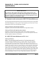
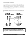
A1. Keyboard, monitor and mouse to LINDY CPU Switch Multiscreen
All of the shared devices plug directly into the relevant ports at the rear of the LINDY
CPU Switch Multiscreen. If you use an AT style keyboard you will need an AT (5 pin
DIN female) to PS/2 (6 pin mini-DIN male) converter.
Cable specification (self-powered operation):
Keyboard, monitor and mouse cables should be no longer than 2 metres.
Cable specification (with optional power adapter):
Keyboard, monitor and mouse extension cables can be used to increase the
distance from LINDY CPU Switch Multiscreen up to 10m. Most keyboards and mice
will also operate at distances of 20 metres.
A2. LINDY CPU Switch Multiscreen to PCs 1 to 4
Cable specifications:
Video - 15 pin high density male D connector to 15 pin high density male D
connector wired as a standard VGA PC to monitor cable. There are two types
commonly available. The best type cables which will give excellent quality are
constructed with coaxial cable cores. Cheaper ‘data’ cables are often used, but can
degrade video quality if used over longer distances. Avoid using 'data' cables longer
than 2 metres unless the video quality is not important. Good quality coaxial video
cables may be run at distances up to 30 metres with little loss of video quality. If you
wish to make use of the DDC (Display Data Channel) capabilities of the LINDY CPU
Switch Multiscreen then you will need to use cables that have the DDC signalling
lines connected (pins 12 and 15 on the 15-way video connector). Not all video
LINDY CPU Switch Multiscreen Installation and Use
Page 40
cables have these DDC lines connected.
Keyboard and PS/2 mice - 6 pin mini-DIN male connector to 6 pin mini-DIN male
connector with all lines connected straight through (1-1,2-2 etc.). If the PC has a 5pin DIN AT style keyboard connector you will need a PS/2 to AT keyboard adapter
6-pin mini-DIN female to 5-pin DIN male (readily available). For ‘interface powered’
operation without the optional power adapter the cables should be no longer than 5
metres (see section 2.4 for more details). For operation with the power adapter,
cables should be no longer than 30 metres.
RS232 serial mice - these require a special converter to connect the RS232 lines
present on the LINDY CPU Switch Multiscreen mouse ports to the RS232 port on a
PC.
Cables should be no longer than 30 metres.
NOTE - There are several common wiring specifications for 6-pin mini-DIN to
9-pin serial adapters. If you have an adapter that has been supplied with a
mouse it may have a completely different internal wiring to that shown above
and may not be compatible with the LINDY CPU Switch Multiscreen
LINDY CPU Switch Multiscreen Installation and Use
Page 41
Recommended cables:
3-in-1 keyboard, video and mouse combination cable - For convenience,
neatness and high video quality we recommend the LINDY brand 3-in-1 combination
cables for the keyboard, mouse and first video head connection. For the additional
video connections we recommend high quality LINDY tri-coax video cables. LINDY
cables are available in various different lengths to suit your requirements. Please
quote the following part codes when ordering from your supplier.
Part Code
33711
33712
33713
33714
33716
Description
3-in-1 LINDY cable, 1 metres long
3-in-1 LINDY cable, 2 metres long
3-in-1 LINDY cable, 3 metres long
3-in-1 LINDY cable, 5 metres long
3-in-1 LINDY cable, 10 metres long *
* The optional power adapter may be required (see section 2.4).
Additional Video Connectors - For the additional video connections we
recommend high quality LINDY Premium or Premium Gold S-VGA video cables.
LINDY cables are available in various different lengths to suit your requirements.
Please quote the following part codes when ordering from your supplier.
Premium S-VGA Cable – Heavily shielded tri-coaxial RGB cable giving you a
crisper display at higher resolutions.
Part Code
37332
37333
37334
37335
37336
37337
37338
Description
Premium S-VGA Monitor Cable, 2 metres long
Premium S-VGA Monitor Cable, 3 metres long
Premium S-VGA Monitor Cable, 5 metres long
Premium S-VGA Monitor Cable, 7.5 metres long
Premium S-VGA Monitor Cable, 10 metres long
Premium S-VGA Monitor Cable, 15 metres long
Premium S-VGA Monitor Cable, 20 metres long
LINDY CPU Switch Multiscreen Installation and Use
Page 42
Premium Gold S-VGA Cable – Premium Gold S-VGA cable is designed for the
highest quality monitor applications, including CAD, DTP and Multimedia
installations when preservation of display quality is a major consideration.
Part Code
37245
37246
37247
37248
37254
37250
37251
37252
37253
Description
Premium Gold S-VGA Monitor Cable, 2 metres long
Premium Gold S-VGA Monitor Cable, 3 metres long
Premium Gold S-VGA Monitor Cable, 5 metres long
Premium Gold S-VGA Monitor Cable, 10 metres long
Premium Gold S-VGA Monitor Cable, 15 metres long
Premium Gold S-VGA Monitor Cable, 20 metres long
Premium Gold S-VGA Monitor Cable, 30 metres long
Premium Gold S-VGA Monitor Cable, 40 metres long
Premium Gold S-VGA Monitor Cable, 50 metres long
A3. Options port pin assignments
The 15 way D connector located on the back of the LINDY CPU Switch Multiscreen
(labelled OPTIONS / FLASH) provides connections for the remote control module
and allows an external RS232 device to control the LINDY CPU Switch Multiscreen.
See section 3.7 for more details.
Pin 9 = GND
Pin 10 = TXD
Pin 11 = RXD
Other pins to be left unconnected
LINDY CPU Switch Multiscreen Installation and Use
Page 43
A.4 Flash upgrade cable connection
The cable connections shown below are to connect either COM1 or COM2 of a PC
to the LINDY CPU Switch Multiscreen to allow flash upgrades.
A.5 RS232 synchronisation cable pin assignments
The cable connections shown below are to connect two LINDY CPU Switch
Multiscreens together for synchronised operation (see section 3.9)
LINDY CPU Switch Multiscreen Installation and Use
Page 44
Appendix B.
Problem Solving
Problem: Poor video quality with smearing fuzziness or ripple.
Action: Use screened coaxial video cables to connect your devices.
Problem: Mouse does not move cursor on screen.
Action: Ensure that the mouse and computer are both connected to LINDY CPU Switch
Multiscreen before power is connected and ensure that the LINDY CPU Switch Multiscreen
is powered on before the attached computer. Ensure that your software is configured to
accept a Microsoft compatible mouse of the type that you have connected (PS/2 or
RS232). If you move the mouse and the activity indicator (dot on 7 segment display) does
not flash then the LINDY CPU Switch Multiscreen is not receiving data from the mouse.
Check the mouse connection to the LINDY CPU Switch Multiscreen, try resetting the mouse
using the reset function (section 2.10) or re-powering the CPU Switch Multiscreen. If you
are attempting to connect the CPU Switch Multiscreen to a CPU with a PS/2 mouse
connection that has not been powered down then you will need to use the mouse
restoration functions F5 or F6 (see section 2.11).
Problem: Keyboard does not function or functions intermittently. Num lock light does not
always come on when the num lock key is pressed.
Action: Some older keyboards were designed for use with specific computers and are not
truly AT or PS/2 compatible. Try another keyboard.
Problem: Mouse causes channel to change.
Action: Some cheaper mice are not fully compatible with the LINDY CPU Switch
Multiscreen and can lose data causing the channel to be changed (if mouse switching of
channels is enabled). If you experience this problem then change the mouse and use a
Microsoft, Logitech, IBM, Compaq or Hewlett-Packard type. Ensure that you are using a
Microsoft compatible mouse driver on your PC. Some other manufacturers’ drivers may
switch the mouse to use a proprietary mouse data format not supported by the LINDY CPU
Switch Multiscreen. If you have unplugged and re-connected a mouse to the LINDY CPU
Switch Multiscreen then ensure that you reset it using the mouse reset function (see 2.10).
Problem: Mouse jumps around the screen after disconnecting the mouse cable or
powering down the LINDY CPU Switch Multiscreen.
Action: If you have disconnected and re-connected a CPU mouse cable or you have
powered down the LINDY CPU Switch Multiscreen then the mouse data format may be out
of synchronisation with that required by the PC (PS/2 or Intellimouse). Try the ‘restore
Intellimouse’ function (F6) to resolve the problem or re-power the CPU.
Problem: Mouse moves very slowly but otherwise functions correctly.
Action: Change the mouse driver to a Microsoft mouse driver or take the action
recommended in section 4.9 of this manual.
LINDY CPU Switch Multiscreen Installation and Use
Page 45