1
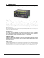
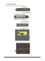
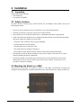
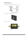
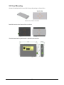
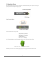
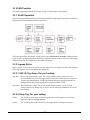
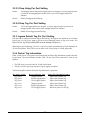
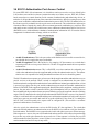
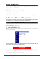
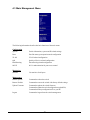
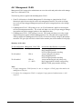
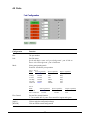
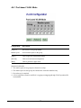
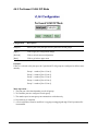
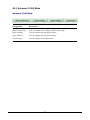
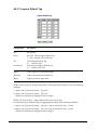
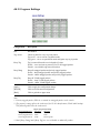
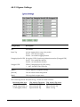
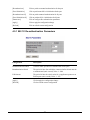
KGD-600
Industrial Web Smart 6-Port Gigabit
Ethernet Switch with Fiber Connectivity
Installation Guide
DOC.070402
-1-
(C) 2006 KTI Networks Inc. All rights reserved. No part of this documentation may be reproduced in
any form or by any means or used to make any directive work (such as translation or transformation)
without permission from KTI Networks Inc.
KTI Networks Inc. reserves the right to revise this documentation and to make changes in content
from time to time without obligation on the part of KTI Networks Inc. to provide notification of such
revision or change.
For more information, contact:
United States
International
KTI Networks Inc.
P.O. BOX 631008
Houston, Texas 77263-1008
Phone:
Fax:
E-mail:
URL:
713-2663891
713-2663893
[email protected]
http://www.ktinet.com/
Fax:
E-mail:
URL:
886-2-26983873
[email protected]
http://www.ktinet.com.tw/
-2-
The information contained in this document is subject to change without prior notice. Copyright (C). All
Rights Reserved.
TRADEMARKS
Ethernet is a registered trademark of Xerox Corp.
WARNING:
This equipment has been tested and found to comply with the limits for a Class A digital device, pursuant
to Part 15 of the FCC Rules. These limits are designed to provide reasonable protection against harmful
interference when the equipment is operated in a commercial environment. This equipment generates,
uses, and can radiate radio frequency energy and if not installed and used in accordance with the
instruction manual may cause harmful interference in which case the user will be required to correct the
interference at his own expense.
NOTICE:
(1) The changes or modifications not expressively approved by the party responsible for compliance
could void the user's authority to operate the equipment.
(2) Shielded interface cables and AC power cord, if any, must be used in order to comply with the
emission limits.
CISPR A COMPLIANCE:
This device complies with EMC directive of the European Community and meets or exceeds the following
technical standard.
EN 55022 - Limits and Methods of Measurement of Radio Interference Characteristics of Information
Technology Equipment. This device complies with CISPR Class A.
CE NOTICE
Marking by the symbol
indicates compliance of this equipment to the EMC directive of the Euro-
pean Community. Such marking is indicative that this equipment meets or exceeds the following technical standards:
EN 55022: Limits and Methods of Measurement of Radio Interference characteristics of Information
Technology Equipment.
EN 50082/1:Generic Immunity Standard -Part 1: Domestic Commercial and Light Industry.
EN 60555-2: Disturbances in supply systems caused by household appliances and similar electrical
equipment - Part 2: Harmonics.
-3-
Table of Contents
1. Introduction .................................................................................................. 6
1.1
1.2
1.3
1.4
Features ................................................................................................................... 7
Product Panels ......................................................................................................... 8
LED Indicators .......................................................................................................... 9
Specifications ........................................................................................................... 9
2. Installation .................................................................................................. 11
2.1 Unpacking ............................................................................................................... 11
2.2 Safety Cautions ...................................................................................................... 11
2.3 Mounting the Switch on a Wall................................................................................. 11
2.4 Din-Rail Mounting .................................................................................................... 12
2.5 Panel Mounting ........................................................................................................ 13
2.6 Applying Power ........................................................................................................ 14
2.7 Reset Button .......................................................................................................... 15
2.8 Making UTP Connections ....................................................................................... 16
2.9 Making Fiber Connection ........................................................................................ 17
2.10 LED Indication ...................................................................................................... 18
2.11 Configuring IP Address and Password for the Switch ............................................ 18
3. Advanced Functions .................................................................................. 19
3.1 Abbreviation ............................................................................................................. 19
3.2 QoS Function .......................................................................................................... 20
3.2.1 Packet Priority Classification ................................................................................ 21
3.2.2 Priority Class Queues .......................................................................................... 21
3.2.3 Egress Service Policy .......................................................................................... 21
3.3 VLAN Function ......................................................................................................... 22
3.3.1 VLAN Operation .................................................................................................... 22
3.3.2 Ingress Rules ....................................................................................................... 22
3.3.2.1 802.1Q Tag Aware Per port setting .................................................................... 22
3.3.2.2 Keep Tag Per port setting .................................................................................. 22
3.3.2.3 Drop Untag Per Port Setting .............................................................................. 23
3.3.2.4 Drop Tag Per Port Setting .................................................................................. 23
3.3.3 Ingress Default Tag Per Port Setting..................................................................... 23
3.3.4 Packet Tag Information ......................................................................................... 23
3.3.5 VLAN Group Table Configuration ........................................................................... 24
3.3.6 VLAN Classification............................................................................................... 24
3.3.7 Packet Forwarding ................................................................................................ 24
3.3.8 Egress Tagging Rules .......................................................................................... 25
3.3.8.1 Egress Settings ................................................................................................. 25
3.3.9 Summary of VLAN Function ................................................................................. 25
3.4 802.1X Authentication Port Access Control ............................................................. 26
-4-
4. Web Management ....................................................................................... 27
4.1 Start Browser Software and Making Connection ..................................................... 27
4.2 Login to the Switch Unit ........................................................................................... 27
4.3 Main Management Menu .......................................................................................... 28
4.4 System .................................................................................................................... 29
4.4.1 Management VLAN ............................................................................................... 30
4.5 Ports ........................................................................................................................ 31
4.6 VLANs ..................................................................................................................... 32
4.6.1 Port-based VLAN Mode ......................................................................................... 33
4.6.2 Port-based VLAN ISP Mode .................................................................................. 34
4.6.3 Advanced VLAN Mode ........................................................................................... 35
4.6.3.1 Ingress Default Tag ............................................................................................ 36
4.6.3.2 Ingress Settings ................................................................................................. 37
4.6.3.3 Egress Settings ................................................................................................. 38
4.6.3.4 VLAN Groups ..................................................................................................... 39
4.6.4 Important Notes for VLAN Configuration ................................................................ 40
4.7 Quality of Service .................................................................................................... 41
4.7.1 802.1p Mapping .................................................................................................... 42
4.7.2 DSCP Mapping ..................................................................................................... 43
4.7.3 QoS Service Policy .............................................................................................. 44
4.8 Port Mirroring ........................................................................................................... 45
4.9 802.1X Configuration ............................................................................................... 46
4.9.1 802.1X Re-authentication Parameters.................................................................. 47
4.10 Statistics................................................................................................................ 48
4.11 Reboot System ...................................................................................................... 49
4.12 Restore Default ..................................................................................................... 49
4.13 Update Firmware / Configuration ........................................................................... 49
4.13.1 Update Firmware ................................................................................................ 49
4.13.2 Upload Configuration File.................................................................................... 50
4.13.3 Backup Configuration File ................................................................................... 50
4.14 Logout ................................................................................................................... 50
Appendix. Factory Default Settings............................................................... 51
-5-
1. Introduction
The KGD-600 is a managed 6-port Gigabit Ethernet switch which is featured with five copper ports,
one mini-GBIC (SFP) port and the following advantages in a small footprint box:
Plug and Play
The switch is shipped with factory default configuration which behaves like an unmanaged Gigabit
switch for workgroup. It provides five 10/100/1000Mbps copper ports for connections to Ethernet, Fast
Ethernet, and Gigabit Ethernet devices. With the featured auto-negotiation function, the switch can
detect and configure the connection speed and duplex automatically. The switch also provides auto
MDI/MDI-X function, which can detect the connected cable and switch the transmission wire pair and
receiving pair automatically. This auto-crossover function can simplify the type of network cables used.
Fiber Connectivity
The mini-GBIC (SFP) port can be installed with an optional SFP optical fiber transceiver to support one
Gigabit fiber connection when needed.
Web Management
The switch is embedded with an Http server which provides management functions for advanced
network functions including Port Control, Quality of Service, and Virtual LAN functions. The management can be performed via Web browser based interface over TCP/IP network.
Virtual LAN (VLAN)
For increasing Tagged VLAN applications, the switch is also featured with powerful VLAN function to
fulfill the up-to-date VLAN requirements. The switch supports both port-based VLAN and tagged
VLAN in per-port basis.
Quality of Service
For advanced application, the switch is featured with powerful Quality of Service (QoS) function which
can classify the priority for received network frames based on the ingress port and frame contents.
Furthermore, many service priority policies can be configured for egress operation in per-port basis.
-6-
Industrial Features
For industrial environment, the devices are designed with the following enhanced features exceeding
that of commercial Ethernet switches:
• High and wide operating Temperature
• Power input interface: Industrial screw terminal block and DC power jack for external commercial power adapter as option
• Screw panel and DIN rail mounting support for industrial enclosure
• Industrial-rated Emission and Immunity performance
1.1 Features
Basic functions
•
•
•
•
•
•
•
•
•
Provides 5 10/100/1000Mbps Gigabit Ethernet ports and 1 SFP port
Provides in-band web-based management interface
All copper ports support auto-negotiation and auto-MDI/MDI-X detection
Provides full wire speed forwarding
Supports 802.3x flow control for full-duplex and backpressure for half-duplex
Provides port status, statistic monitoring and control function
Supports port-based and 802.1Q Tag-based VLAN
Provides QoS function
Provides port mirroring function
Management functions
• Web-based browsing interface
• Port configuration control and status monitoring
• Quality of Service (QoS) control for packet traffic
• Port-based and Tagged Virtual LAN (VLAN) function
• 802.1x authentication for port access control
• Port mirroring function
• Configuration file backup and upload
• In-band embedded firmware upgrade function
-7-
1.2 Product Panels
The following figure illustrates the faces of the switch:
-8-
1.3 LED Indicators
LED
Function
POWER
Power status
LNK/1000M/ACT Network port 1000M link status (Port 1 - Port 5)
LNK/100M/ACT Network port 100M link status (Port 1 - Port 5)
LNK/10M/ACT
Network port 10M link status (Port 1 - Port 5)
P6 LNK
Port 6 1000M link status
P6 OL
Port 6 optical link status
1.4 Specifications
10/100/1000 Copper Ports
Compliance
IEEE 802.3 10Base-T, IEEE 802.3u 100Base-TX,
IEEE 802.3u 1000Base-T
Connectors
Shielded RJ-45 jacks
Pin assignments
Auto MDI/MDI-X detection
Configuration
Auto-negotiation or software control
Transmission rate
10Mbps, 100Mbps, 1000Mbps
Duplex support
Full/Half duplex
Network cable
Cat.5 UTP
1000Mbps Mini-GBIC Fiber Port
Compliance
IEEE 802.3z 1000Base-SX/LX (mini-GBIC)
Connectors
SFP for optional SFP type fiber transceivers
Configuration
Auto/Forced, 1000Mbps, Full duplex
Transmission rate
1000Mbps
Network cables
MMF 50/125 60/125, SMF 9/125
Eye safety
IEC 825 compliant
Switch Functions
MAC Addresses Table
8K entries
Forwarding & filtering
Non-blocking, full wire speed
Switching technology
Store and forward
Maximum packet length 1526 bytes
Flow control
IEEE 802.3x pause frame base for full duplex operation
Back pressure for half duplex operation
VLAN function
Port-based VLAN and IEEE 802.1Q Tag-based VLAN
QoS function
Port-based, 802.1p-based, IP DSCP-based
-9-
Port control
Port configuration control via software management
Port Mirroring
Mirror received frames to a sniffer port
Software Management Functions
Interfaces
Web browser
Management objects
System configuration - IP settings, Name, Password
Port configuration control and status
VLAN function settings
QoS function settings
Port mirroring settings
802.1x authentication port-access control
Port Statistic
Reboot, restore factory default, update firmware
DC Power Input
Interfaces
DC IN Jack ( -D 6.3mm / + D 2.0mm)
DC IN Terminal Block - screw type
Operating Input Voltages +5 ~ 30VDC(+/-5%)
Power Consumption
3.6W max. @7.5V
Mechanical
Dimension (base)
144 x 104.5 x 26 mm
Housing
Enclosed metal with no fan
Mounting Support
Din-rail mounting, Panel mounting, Wall mounting, Desktop mounting
Environmental
Operating Temperature Typical -20oC ~ 70oC
Storage Temperature
-20oC ~ 85oC
Relative Humidity
10% ~ 90%
Special Test
NEMA TS2-2003 Environment:
Endurance Vibration, Mechanical shock test, Temperature/Humidity test
(Condition combination : -34oC ~ +74oC, 0 ~90%RH, +5 ~ +30VDC)
Electrical Approvals
FCC
Part 15 rule Class A
CE
EMC, CISPR22 Class A
Safety
IEC60950-1 / EN60950
-10-
2. Installation
2.1 Unpacking
The product package contains:
• The switch unit
• One product CD-ROM
2.2 Safety Cautions
To reduce the risk of bodily injury, electrical shock, fire, and damage to the product, observe the
following precautions.
• Do not service any product except as explained in your system documentation.
• Opening or removing covers may expose you to electrical shock.
• Only a trained service technician should service components inside these compartments.
• If any of the following conditions occur, unplug the product from the electrical outlet and replace
the part or contact your trained service provider:
- The power cable, extension cable, or plug is damaged.
- An object has fallen into the product.
- The product has been exposed to water.
- The product has been dropped or damaged.
- The product does not operate correctly when you follow the operating instructions.
• Do not push any objects into the openings of your system. Doing so can cause fire or electric
shock by shorting out interior components.
• Operate the product only from the type of external power source indicated on the electrical
ratings label. If you are not sure of the type of power source required, consult your service
provider or local power company.
2.3 Mounting the Switch on a Wall
The switch can be mounted on a desktop or shelf or a wall. Make sure that there is proper heat
dissipation from and adequate ventilation around the device. Do not place heavy objects on the device.
-11-
2.4 Din-Rail Mounting
The steps to mount the switch on a Din-rail are:
One Din-rail mounting bracket is provided in the product package as shown below:
Install the bracket on the bottom of the switch unit.
Mount the device on a Din-rail.
-12-
2.5 Panel Mounting
One panel mounting bracket is provided in the product package as shown below:
Install the bracket on the bottom of the switch unit.
The final dimension after panel bracket is installed is shown below:
-13-
2.6 Applying Power
The switch provides two types of power interfaces, terminal block and DC power jack for receiving DC
power input from external power supply system.
Using Terminal Blocks
Three terminal contacts are provided:
Vdc Positive (+) terminal
Vdc Negative (-) terminal
Chassis ground
( Vdc : +5V ~ +30VDC)
One 3P terminal plugs are provided together with the switch. The plug is shown below:
Power wires : 24 ~ 12AWG (IEC 0.5~2.5mm2)
Install the power source wires with the plug properly. Then, plug in the terminal block socket.
-14-
Using DC Power Jack
When an external power system is not available, the switch provides a DC jack to receive power from
typical AC-DC power adapter alternatively.
AC Power Adapters: Optional commercial rated adapters are available for purchasing.
AC input power:
AC power voltage of your area, options Rated AC120V/60Hz DC7.5V 1A
Rated AC230V/50Hz DC7.5V 1A
Rated AC100V/50-60Hz DC7.5V 1A
Rated AC100V/50-60Hz DC5V 1A
Rated AC240V/50Hz DC7.5V 1A
Note: Before you begin the installation, check the AC voltage of your area. The AC power
adapter which is used to supply the DC power for the unit should have the AC voltage
matching the commercial power voltage in your area.
2.7 Reset Button
The reset button is used to perform a reset to the switch. It is not used in normal cases and can be used
for diagnostic purpose. If any network hanging problem is suspected, it is useful to push the button to
reset the switch without turning off the power. Check whether the network is recovered.
The button can also be used to restore the software configuration settings to factory default values.
The operations are:
Operation
Function
Press the button more than 5 seconds when power up
Press the button and release during switch operation
Restore factory default settings
Reboot the switch
-15-
2.8 Making UTP Connections
The 10/100/1000 copper ports support the following connection types and distances:
Network Cables
10BASE-T:
2-pair UTP Cat. 3,4,5 , EIA/TIA-568B 100-ohm
100BASE-TX: 2-pair UTP Cat. 5, EIA/TIA-568B 100-ohm
1000BASE-T: 4-pair UTP Cat. 5 or higher (Cat.5e is recommended), EIA/TIA-568B 100-ohm
Link distance: Up to 100 meters
Auto MDI/MDI-X Function
This function allows the port to auto-detect the twisted-pair signals and adapts itself to form a valid
MDI to MDI-X connection with the remote connected device automatically. No matter a straight
through cable or crossover cable is connected, the ports can sense the receiving pair automatically and
configure itself to match the rule for MDI to MDI-X connection. It simplifies the cable installation.
Auto-negotiation Function
The ports are featured with auto-negotiation function and full capability to support connection to any
Ethernet devices. The port performs a negotiation process for the speed and duplex configuration with
the connected device automatically when each time a link is being established. If the connected device
is also auto-negotiation capable, both devices will come out the best configuration after negotiation
process. If the connected device is incapable in auto-negotiation, the switch will sense the speed and
use half duplex for the connection.
Port Configuration Management
For making proper connection to an auto-negotiation incapable device, it is suggested to use port control function via software management to set forced mode and specify speed and duplex mode which
match the configuration used by the connected device.
-16-
2.9 Making Fiber Connection
The mini-GBIC (SFP) port must be installed with an SFP fiber transceiver for making fiber connection. Your switch may come with an SFP transceiver pre-installed when it is shipped.
Installing SFP Fiber Transceiver
To install an SFP fiber transceiver into mini-GBIC port, the steps are:
1. Turn off the power to the switch.
2. Insert the SFP fiber transceiver into the mini-GBIC port. Normally, a bail is provided for every
SFP transceiver. Hold the bail and make insertion.
3. Until the SFP transceiver is seated securely in the slot, place the bail in lock position.
Connecting Fiber Cables
LC connectors are commonly equipped on most SFP transceiver modules. Identify TX and RX
connector before making cable connection. The following figure illustrates a connection example
between two fiber ports:
Make sure the Rx-to-Tx connection rule is followed on the both ends of the fiber cable.
Network Cables
Multimode (MMF) - 50/125, 62.5/125
Single mode (SMF) - 9/125
-17-
2.10 LED Indication
LED
Function
State
Interpretation
POWER
Power status
ON
OFF
The power is supplied to the switch.
The power is not supplied to the switch.
LNK/1000M/ACT
Port link status
ON
A 1000M link is established. (No traffic)
BLINK Port link is up and there is traffic.
OFF
Port link is down.
LNK/100M/ACT
Port link status
ON
A 100M link is established. (No traffic)
BLINK Port link is up and there is traffic.
OFF
Port link is down.
LNK/1000M/ACT
Port link status
ON
A 10M link is established. (No traffic)
BLINK Port link is up and there is traffic.
OFF
Port link is down.
P6 LNK
Port6 link status
ON
A 1000M link is established on Port 6.
BLINK Port 6 link is up and there is traffic.
OFF
Port 6 link is down.
P6 OL
Port6 optical link
ON
OFF
Optical signal is detected on Port 6.
No optical signal is detected on Port 6.
2.11 Configuring IP Address and Password for the Switch
The switch is shipped with the following factory default settings for software management :
Default IP address of the switch : 192.168.0.2 / 255.255.255.0
The IP Address is an identification of the switch in a TCP/IP network. Each switch should be designated a new and unique IP address in the network. Refer to Web management interface for System
Configuration.
The switch is shipped with factory default password 123 for software management.
The password is used for authentication in accessing to the switch via Http web-based interface. For
security reason, it is recommended to change the default settings for the switch before deploying it to
your network. Refer to Web management interface for System Configuration.
-18-
3. Advanced Functions
To help a better understanding about the software management interfaces, this chapter describes some
advanced functions provided by the switch.
3.1 Abbreviation
Ingress Port : Ingress port is the input port on which a packet is received.
Egress Port : Egress port is the output port from which a packet is sent out.
IEEE 802.1Q Packets : A packet which is embedded with a VLAN Tag field
VLAN Tag : In IEEE 802.1Q packet format, 4-byte tag field is inserted in the original Ethernet frame
between the Source Address and Type/Length fields. The tag is composed of :
#of bits
Frame field
16
TPID
3
User priority
1
CFI
12
VID
TPID : 16-bit field is set to 0x8100 to identify a frame as an IEEE 802.1Q tagged packet
User Priority : 3-bit field refer to the 802.1p priority
CFI : The Canonical Format Indicator for the MAC address is a 1 bit field.
VID : VLAN identifier, 12-bit field identifies the VLAN to which the frame belongs to.
Untagged packet : A standard Ethernet frame with no VLAN Tag field
Priority-tagged packet : An IEEE 802.1Q packet which VID filed value is zero (VID=0)
VLAN-Tagged packet : An IEEE 802.1Q packet which VID filed value is not zero (VID<>0)
PVID (Port VID)
PVID is the default VID of an ingress port. It is often used in VLAN classification for untagged
packets. It is also often used for egress tagging operation.
DSCP : Differentiated Service Code Point, 6-bit value field in an IP packet
VLAN Table lookup : The process of searching VLAN table to find a VLAN which matches the
given VID index
MAC address table lookup : The process of searching MAC address table to find a MAC entry
which matches the given destination MAC address and the port where the MAC address is located
Packet forwarding : also known as packet switching in a network switch based on MAC address
table and VLAN table information
VLAN forwarding : the operation that a packet is forwarded to an egress destination port based on
VLAN table information
VLAN group : configuration information about a VLAN which can be recognized in the switch. The
information includes a VID associated to the VLAN, member ports, and some special settings.
-19-
3.2 QoS Function
The switch provides a powerful Quality of Service (QoS) function to guide the packet forwarding in
four priority classes. The versatile classification methods can meet most of the application needs. The
following figure illustrates the QoS operation flow when a packet received on the ingress port until it is
transmitted out from the egress port:
-20-
3.2.1 Packet Priority Classification
Each received packet is examined and classified into one of four priority classes, Class 3, Class 2,
Class 1 and Class 0 upon reception. The switch provides the following classification methods:
802.1p classification : use User Priority tag value in the received IEEE 802.1Q packet to map to one
priority class
DSCP classification : use DSCP value in the received IP packet to map to one priority class
Port-based classification : used when 802.1p and DSCP are disabled or fail to be applied
They all can be configured to be activated or not. More than one classification methods can be enabled
at the same time. However, 802.1p classification is superior than DSCP classification.
802.1p mapping tables : Each ingress port has its own mapping table for 802.1p classification.
DSCP mapping table : All ingress ports share one DSCP mapping table for DSCP classification.
Default port priority : A port default priority class is used when port-based classification is applied
All configuration settings are in per port basis except that DSCP mapping table is global to all ports. A
received packet is classified into one of four priority class before it is forwarded to an egress port.
3.2.2 Priority Class Queues
Each egress port in the switch is equipped with four priority class egress queues to store the packets
for transmission. A packet is stored into the class queue which is associated to the classified priority
class. For example, a packet is stored into Class 3 egress queue if it is classified as priority Class 3.
3.2.3 Egress Service Policy
Each port can be configured with an egress service policy to determine the transmission priority among
four class queues. By default, higher class number has higher priority than the lower class numbers.
Four policies are provided for selection as follows:
•
•
•
•
Strict priority : Packets in high priority class queue are sent first until the queue is empty
Weighted ratio priority Class 3:2:1:0 = 4:3:2:1 : four queues are served in 4:3:2:1 ratio
Weighted ratio priority Class 3:2:1:0 = 5:3:1:1 : four queues are served in 5:3:1:1 ratio
Weighted ratio priority Class 3:2:1:0 = 1:1:1:1 : four queues are served equally
Strict priority policy lets high priority class queue is served first until it is empty. Lower priority queue
may not get any service (or egress bandwidth) when higher priority traffic is heavy for long time. Three
weighted ratio policies are provided to resolve such problem. Four class queues are served in weighted
round robin basis. Every priority class can get a guaranteed ratio for the egress bandwidth.
-21-
3.3 VLAN Function
The switch supports port-based VLAN, 802.1Q Tag VLAN and eight VLAN groups.
3.3.1 VLAN Operation
The following figure illustrates the basic VLAN operation flow beginning from a packet received on an
ingress port until it is transmitted from an egress port.
The following sections describe the VLAN processes and Advanced VLAN mode settings provided
by the switch. A global setting means the setting is applied to all ports of the switch. A per port setting
means each port can be configured for the setting respectively.
3.3.2 Ingress Rules
When a packet is received on an ingress port, the ingress rules are applied for packet filtering and
packet tag removal. The related Ingress port settings are:
3.3.2.1 802.1Q Tag Aware Per port setting
Tag-aware -802.1Q Tag Aware mode is used. The switch examines the tag content of every
received packets. For a VLAN tagged packet, the packet VLAN tag data is retrieved
as packet tag information for VLAN classification and egress tagging operation. For
untagged packet and priority-tagged packet, port-based mode is used.
Tag-ignore - Port-based mode is used. The switch ignores the tag content of every received
packets. Ingress Port Default Tag is always used as packet tag information for VLAN
classification.
3.3.2.2 Keep Tag Per port setting
Enable -
The VLAN tag in the received VLAN tagged packet will be kept as it is and is not
stripped in whole forwarding operation.
Disable -
The VLAN tag data in the received VLAN tagged packet is stripped (removed).
-22-
3.3.2.3 Drop Untag Per Port Setting
Enable -
All untagged packets and priority-tagged packets are dropped. A priority-tagged packet
is treated as an untagged packet in this switch. Only VLAN-tagged packets are
admitted.
Disable -
Disable Untagged packet filtering
3.3.2.4 Drop Tag Per Port Setting
Enable -
All VLAN-tagged packets are dropped. A priority-tagged packet is treated as an
untagged packet in this switch. Only untagged packets are admitted.
Disable -
Disable VLAN-tagged packet filtering
3.3.3 Ingress Default Tag Per Port Setting
Each port can be configured with one Ingress Default Tag. This ingress port default tag is used when
ingress port is in Tag-ignore mode or for the received untagged packets in Tag-aware mode. The
Ingress Default Tag includes PVID, CFI and User Priority configuration.
When Ingress port default tag is used, it is copied as packet associated Packet Tag Information for
VLAN classification. The PVID is used as index to one VLAN group in VLAN group table.
3.3.4 Packet Tag Information
Under VLAN process, every packet is associated with one Packet Tag information in packet forwarding operation. The tag information includes VID, CFI and User Priority data and is used for two
purposes:
• The VID in tag is used as index for VLAN classification.
• The tag is used for egress tag insertion if egress tagging is enabled.
The following table lists how the Packet Tag information is generated:
Tag Aware setting
Tag-ignore
Tag-ignore
Tag-ignore
Tag-aware
Tag-aware
Tag-aware
Received Packet Type
Untagged packet
Priority-tagged packet
VLAN-tagged packet
Untagged packet
Priority-tagged packet
VLAN-tagged packet
-23-
Packet Tag information source
Ingress Port Default Tag
Ingress Port Default Tag
Ingress Port Default Tag
Ingress Port Default Tag
Ingress Port Default Tag
Received packet VLAN Tag
3.3.5 VLAN Group Table Configuration
The switch provides a table of eight VLAN groups to support up to eight VLANs at the same time.
Each VLAN group is associated to one unique VLAN. The table is referred for VLAN classification.
A VLAN group contains the following configuration settings:
VID : 12-bit VLAN Identifier index to the VLAN to which the group is associated
Member Ports : the admitted egress ports for packets belonging to this VLAN
Source Port Check : the ingress port of the packet must also be the member port of this VLAN.
Otherwise, the packet is discarded.
3.3.6 VLAN Classification
VLAN classification is a process to classify a VLAN group to which a received packet belongs. The
VID of the generated Packet Tag information associated to the received packet is used as an index for
VLAN group table lookup. The VID matched VLAN group will be used for packet forwarding. If no
matched VLAN group is found in table lookup, the packet is dropped.
Refer to section 3.2.4 for details about how the Packet Tag information is generated.
The member ports specified in the matched VLAN group are the admitted egress port range for the
packet. The packet will never be forwarded to other ports which are not in the member ports.
The Source Port Check setting of the matched VLAN group is also referred. If it is enabled, the
ingress port will be checked whether it is a member port of this group.
3.3.7 Packet Forwarding
The forwarding is a process to forward the received packet to one or more egress ports. The process
uses the following information as forwarding decision:
•
•
•
•
Member ports of the matched VLAN group : the egress port range for forwarding
Source Port Check setting of the matched VLAN group : check ingress port membership
The packet destination MAC address : for MAC address table loop up
The switch MAC address table : to find the associated port where a MAC address is learned
If the MAC address table lookup is matched and the learned port is the VLAN member port, the
packet is forwarded to the port (egress port). If the lookup failed, the switch will broadcast the packet
to all member ports.
-24-
3.3.8 Egress Tagging Rules
Egress Tagging rules are used to make change to the packet before it is stored into egress queue of an
egress port. Three egress settings are provided for each port and are described as follows:
3.3.8.1 Egress Settings
Insert Tag (per port setting)
Enable Insert the Tag data of the associated Packet Tag information into the packet
Disable -
No tagging is performed.
Untagging Specific VID (per port setting)
Enable No tag insertion if the VID data of the associated Packet Tag information matches the
Untagged VID configured in next setting even [Insert Tag] is enabled.
Disable -
This rule is not applied.
3.3.9 Summary of VLAN Function
VLAN Modes
Port-based VLAN Mode : simple port-based 2-VLAN-groups mode
Port-based VLAN ISP Mode : simple port-based 5-VLAN-groups mode
Advanced VLAN Mode : Full VLAN configuration for port-based and Tag-based VLAN
Advanced VLAN Mode
Egress Settings (per port) : [Tag Aware], [Keep Tag], [Drop Untag], [Drop Tag]
Ingress Default Tag (per port) : [PVID], [CFI], [User Priority]
VLAN Groups (global) : 8 VLAN groups
VLAN Group Settings (per group) : [VID], [Member Ports], [Source Port Check]
Egress Settings : [Insert Tag], [Untagging Specific VID], [Untagged VID]
VLAN range supported : 1 ~ 4095 (eight VLANs at the same time)
[PVID] [VID] [Untagged VID] value range : 1 ~ 4095
-25-
3.4 802.1X Authentication Port Access Control
For some IEEE 802 LAN environments, it is desirable to restrict access to the services offered by the
LAN to those users and devices that are permitted to make use of those services. IEEE 802.1X Portbased network access control function provide a means of authenticating and authorizing devices attached to a LAN port that has point-to-point connection characteristics, and of preventing access to that
port in cases in which the authentication and authorization process fails. The 802.1X standard relies on
the client to provide credentials in order to gain access to the network. The credentials are not based on
a hardware address. Instead, they can be either a username/password combination or a certificate. The
credentials are not verified by the switch but are sent to a Remote Authentication Dial-In User Service
(RADIUS) server, which maintains a database of authentication information. 802.1X consists of three
components for authentication exchange, which are as follows:
• An 802.1X authenticator: This is the port on the switch that has services to offer to an end device,
provided the device supplies the proper credentials.
• An 802.1X supplicant: This is the end device; for example, a PC that connects to a switch that is
requesting to use the services (port) of the device. The 802.1X supplicant must be able to respond to
communicate.
• An 802.1X authentication server: This is a RADIUS server that examines the credentials provided to the authenticator from the supplicant and provides the authentication service. The authentication server is responsible for letting the authenticator know if services should be granted.
The 802.1X authenticator operates as a go-between with the supplicant and the authentication server to
provide services to the network. When a switch is configured as an authenticator, the ports of the
switch must then be configured for authorization. In an authenticator-initiated port authorization, a client
is powered up or plugs into the port, and the authenticator port sends an Extensible Authentication
Protocol (EAP) PDU to the supplicant requesting the identification of the supplicant. At this point in the
process, the port on the switch is connected from a physical standpoint; however, the 802.1X process
has not authorized the port and no frames are passed from the port on the supplicant into the switching
engine. If the PC attached to the switch did not understand the EAP PDU that it was receiving from the
switch, it would not be able to send an ID and the port would remain unauthorized. In this state, the port
would never pass any user traffic and would be as good as disabled. If the client PC is running the
802.1X EAP, it would respond to the request with its configured ID. (This could be a username/
password combination or a certificate.)
After the switch, the authenticator receives the ID from the PC (the supplicant). The switch then
passes the ID information to an authentication server (RADIUS server) that can verify the identification information. The RADIUS server responds to the switch with either a success or failure message.
If the response is a success, the port will be authorized and user traffic will be allowed to pass through
the port like any switch port connected to an access device. If the response is a failure, the port will
remain unauthorized and, therefore, unused. If there is no response from the server, the port will also
remain unauthorized and will not pass any traffic.
-26-
4. Web Management
The switch features an http server which can serve the management requests coming from any web
browser software over TCP/IP network.
Web Browser
Compatible web browser software with JAVA script support
Microsoft Internet Explorer 4.0 or later
Netscape Communicator 4.x or later
Set IP Address for the System Unit
Before the switch can be managed from a web browser software, make sure a unique IP address is
configured for the switch.
4.1 Start Browser Software and Making Connection
Start your browser software and enter the IP address of the switch unit to which you want to connect.
The IP address is used as URL for the browser software to search the device.
URL : http://xxx.xxx.xxx.xxx/
Factory default IP address : 192.168.0.2
4.2 Login to the Switch Unit
When browser software connects to the switch unit successfully, a Login screen is provided for you to
login to the device as follows:
The switch will accept only one successful management connection at the same time. The other connection attempts will be prompted with a warning message.
A new connection will be accepted when the current user logout successfully or auto logout by the
switch due to no access for time out of 3 minutes.
System Configuration is displayed after a successful login.
-27-
4.3 Main Management Menu
The following information describes the basic functions of the main menu.
Configuration
System
Switch information, system and IP related settings
Ports
Port link status, port operation mode configuration
VLAN
VLAN related configuration
QoS
Quality of Service related configuration
Port Mirroring
Port mirroring related configuration
802.1X
802.1x authentication for port access control
Monitoring
Statistics
List statistics for all ports
Maintenance
Reboot System
Command to reboot the switch
Restore Default
Command to restore the switch with factory default settings
Update Firmware
Command to update the switch firmware,
Command to update the switch configuration (upload file)
Command to backup configuration file to your PC
Logout
Command to logout from the switch management
-28-
4.4 System
Configuration
Description
MAC Address
The MAC address factory configured for the switch
It can not be changed in any cases.
S/W Version
The firmware version currently running
H/W Version
The hardware version currently operating
Management VLAN
- VID
- CFI
- User priority
Set management VLAN information
VLAN ID configured for web management to the switch
CFI value for web reply packets from the switch
Priority value for web reply packets from the switch
IP Address
Set IP address for the switch management
Subnet Mask
Set Subnet mask for IP address for the switch management
Gateway
Set Default gateway IP address for the switch management
Name
Set the system name for this switch unit
Password
Set new password
[Apply]
Click to apply the configuration change
[Refresh]
Click to refresh current configuration
Note:
It is suggested to give each switch unit a system name as an alternative unique
identification beside IP address.
-29-
4.4.1 Management VLAN
Management VLAN settings allow administrator to access the switch and perform the switch management over a dedicated VLAN.
The following rules are applied with the Management VLAN:
1. If the VLAN function is disabled, Management VLAN settings are ignored and no VLAN
limitation is applied in accessing the switch web management interface. The switch web (http)
server only accepts untagged management packets and replies untagged packets to the management host.
2. If [Management VLAN - VID] settings is zero, no VLAN limitation is applied in accessing the
switch web management interface. The switch web (http) server only accepts untagged management packets and replies untagged packets to the management host.
3. If [Management VLAN - VID] settings is not zero, The switch web (http) server only accepts
tagged management packets matched [Management VLAN -VID] and replies tagged packets
with tag composed of [Management VLAN] VID, CFI and User Priority settings to the management host. The egress port will also be limited in the member ports of the matched VLAN group.
Summary of the rules:
VLAN Configuration Management VLAN VID
VLAN disabled
Ignore
VLAN enabled
VID=0
VLAN enabled
VID<>0
( 1 ~ 4095)
Switch Embedded Web Server operation
Accept untagged web packets
Reply untagged packets
No VLAN group member checking
Accept untagged web packets
Reply untagged packets
No VLAN group member checking
Accept matched tagged web packets only
Reply tagged packets with the configured tag
Matched VLAN group member checking
Notes:
1. To apply management VLAN function, be sure to configure a VLAN group that matches the
management VID first.
2. No matter how management VLAN is configured, login password authentication is still
required.
-30-
4.5 Ports
Configuration
Function
Port
The port number
Link
Port link status
Speed and duplex status with green background - port is link on
Down with red background - port is link down
Mode
Select port operating mode
Disabled - disable the port operation
Port 1 - Port 5
Mode
Auto-negotiation
Auto
Enable
10 Half
Disable
10 Full
Disable
100 Half
Disable
100 Full
Disable
1000 Full
Enable
Speed capability
10, 100, 1000M
10M
10M
100M
100M
1000M
Port 6
Mode
Auto-negotiation
1000 Full
Enable
Force 1000 Full
Disable
Duplex capability
Full, Half
Half
Full
Half
Full
Full
Speed capability
1000M
1000M
Duplex capability
Full
Full
Flow Control
Set port flow control function
V - set to enable 802.3x pause flow control for ingress and egress
[Apply]
Click to apply the configuration change
[Refresh]
Click to refresh current configuration
-31-
4.6 VLANs
VLAN Configuration
Description
VLAN Disable
Select to disable VLAN function
All ports are allowed to communicate with each others freely with
no VLAN limitation.
Port-based VLAN Mode
Simple configuration for 2 port-based VLAN groups
Port-based VLAN ISP Mode
Simple configuration for 5 port-based VLAN groups
Advance VLAN Mode
Full VLAN configuration for port-based and Tag-based VLAN
[Apply]
Click to apply the configuration change
[Refresh]
Click to refresh current configuration
-32-
4.6.1 Port-based VLAN Mode
Configuration
Description
Group 1, 2
Port-based VLAN group number
Member ports
Select member ports for the group
[Apply]
Click to apply the configuration change
[Refresh]
Click to refresh current configuration
[Back]
Click to go back to upper menu
Operation in this mode:
1. The member ports of two groups are allowed to overlap.
2. The member ports in same group can communicate with other members only.
3. No packet tag is examined.
4. A received packet will not be modified (i.e. tagging or untagging) through VLAN operation till it
is transmitted.
-33-
4.6.2 Port-based VLAN ISP Mode
Configuration
Description
Joint port
Select a port as the joint port for all 5 port-based VLAN groups
[Apply]
Click to apply the configuration change
[Refresh]
Click to refresh current configuration
[Back]
Click to go back to upper menu
Example:
If Port 6 is selected as the joint port, the 5 port-based VLAN groups are configured as follows automatically:
Group 1 - member [Port 1, Port 6]
Group 2 - member [Port 2, Port 6]
Group 3 - member [Port 3, Port 6]
Group 4 - member [Port 4, Port 6]
Group 5 - member [Port 5, Port 6]
Mode Operation :
1. The joint port is the shared member port for all groups.
2. Two member ports are configured in each group.
3. The member ports in same group can communicate with other only.
4. No packet tag is examined.
5. A received packet will not be modified (i.e. tagging or untagging) through VLAN operation till it
is transmitted.
-34-
4.6.3 Advanced VLAN Mode
Configuration
Description
Ingress Default Tag
Click to configure per port Ingress Default Tag settings
Ingress Settings
Click to configure per port ingress settings
Egress Settings
Click to configure per port egress settings
VLAN Groups
Click to configure VLAN group table
-35-
4.6.3.1 Ingress Default Tag
Configuration
Description
Port
Port number
PVID
Port VID, VID for Ingress Default Tag
1 ~ 4095 - decimal 12-bit VID value
CFI
CFI for Ingress Default Tag
0, 1 - 1-bit CFI value
User Priority
User priority for Ingress Default Tag
0 ~ 7 - decimal 3-bit value
[Apply]
Click to apply the configuration change
[Refresh]
Click to refresh current configuration
[Back]
Click to go back to upper menu
PVID is used as index for VLAN classification (VLAN group table lookup) in one of the following
conditions:
1. Ingress port [Tag Aware] setting = Tag-ignore
2. Ingress port [Tag Aware] setting = Tag-aware
and the received packet is untagged or priority-tagged
[PVID+CFI+User Priority] = Ingress Default Tag for the ingress port
It is used as the tag for insertion in egress tagging operation in one of the following conditions:
1. Ingress port [Tag Aware] setting = Tag-ignore, Egress port [Insert Tag] = Enable
2. Ingress port [Tag Aware] setting = Tag-aware, Egress port [Insert Tag] = Enable
and the received packet is untagged or priority-tagged
-36-
4.6.3.2 Ingress Settings
Configuration
Description
Port
Port number
Tag Aware
Check tag data for every received packet
Tag-aware - set to activate Tag-based mode
Tag-ignore - set to use port-based mode and ignore any tag in packet
Keep Tag
Tag is removed from the received packet if exists
Enable - set to activate tag removal for VLAN-tagged packets
Disable - set to disable tag removal function
Drop Untag
Drop all untagged packets and priority-tagged packets
Enable - drop untagged packets and priority-tagged packets
Disable - admit untagged packets and priority-tagged packets
Drop Tag
Drop all VLAN-tagged packets
Enable - drop VLAN-tagged packets
Disable - admit VLAN-tagged packets
[Apply]
Click to apply the configuration change
[Refresh]
Click to refresh current configuration
[Back]
Click to go back to upper menu
Note:
1. Priority-tagged packet (VID=0) is treated as untagged packet in the switch.
2. [Tag Aware] setting affects the index used for VLAN classification (VLAN table lookup).
The following table lists the index used:
Received packet type
Untagged
Priority-tagged (VID=0)
VLAN-tagged (VID>0)
Ingress [Tag Aware] setting
Tag-ignore
Tag-aware
PVID
PVID
PVID
PVID
PVID
Packet tag VID
3. Both [Drop Untag] and [Drop Tag] are set to Disable to admit all packets.
-37-
4.6.3.3 Egress Settings
Configuration
Description
Port
Port number
Insert Tag
Activate tagging (Insert a tag to the packet)
Enable - set to activate tagging
Disable - set to disable tagging function
Untagging Specific VID No tagging if VID of packet tag information matches [Untagged VID]
Enable - set to enable this function
Disable - set to disable this function
Untagged VID
VID for [Untagging Specific VID] setting
1 ~ 4095 - decimal 12-bit VID value
[Apply]
Click to apply the configuration change
[Refresh]
Click to refresh current configuration
[Back]
Click to go back to upper menu
The inserted tag sources when [Insert Tag] = Enable are listed as follows:
Received packet type
Untagged
Priority-tagged (VID=0)
VLAN-tagged (VID>0)
[Tag Aware]=Tag-ignore
Ingress Default Tag
Ingress Default Tag
Ingress Default Tag
-38-
[Tag Aware]=Tag-aware
Ingress Default Tag
Ingress Default Tag
Packet own tag
4.6.3.4 VLAN Groups
Configuration
Description
Group
Group number
VID
VID of the VLAN to which this group is associated
1 ~ 4095 - decimal 12-bit VID value
Member Ports
Select the admitted egress ports for the packets belong to the VLAN
Port 1 ~ 6 - click to select
Source Port Check
Check whether the ingress port is the member port of the VLAN
Enable - set to enable this check, the packet is dropped if ingress port is
not member port of the VLAN.
Disable - set to disable this check
[Apply]
Click to apply the configuration change
[Refresh]
Click to refresh current configuration
[Back]
Click to go back to upper menu
-39-
4.6.4 Important Notes for VLAN Configuration
Some considerations should be checked in configuring VLAN settings:
1. Switch VLAN Mode selection
It is suggested to evaluate your VLAN application first and plan your VLAN configuration
carefully before applying it. Any incorrect setting might cause network problem.
2. Double Tagged in Advanced VLAN Mode
For a received packet, Ingress port [Keep Tag] setting and Egress port [Insert Tag] setting are
enabled at the same time. It will cause the packet double-tagged when egress. Although, it is
often applied in Q-in-Q provider bridging application. However, such condition should be avoided
in normal VLAN configuration. See table below:
Ingress port Egress port
[Keep Tag] [Insert Tag]
Enable
Enable
Enable
Enable
Received Packet
Priority-tagged
VLAN-tagged
-40-
Packet Transmitted
Double-tagged
Double-tagged
4.7 Quality of Service
QoS Configuration
Description
Port
Port number
802.1p
802.1p priority classification
Enable - set to enable this classification to the port for priority-tagged and
VLAN-tagged packets
Disable - 802.1p classification is not applied to the port
DSCP
DSCP classification
Enable - set to enable DSCP classification to the port for IP packets
Disable - DSCP classification is not applied to the port
Port Priority
Port default priority class, it is used as a port-based QoS mode when
802.1p and DSCP classifications are disabled. It is also used as default
priority class for the received packet when both 802.1p and DSCP classification failed in classification.
Class 3 ~ Class 0 - priority class
[802.1p Mapping]
Click to configure 802.1p mapping tables.
[DSCP Mapping]
Click to configure DSCP mapping table.
[Service Policy]
Click to configure per port egress service policy mode.
[Apply]
Click to apply the configuration change
[Refresh]
Click to refresh current configuration
Note:
802.1p classification is superior over DSCP classification if both are enabled. That means if a
received packet is classified successfully in 802.1p classification, the classified priority class is
used directly for the packet and the result of DSCP classification is ignored.
-41-
4.7.1 802.1p Mapping
Configuration
Description
Port n
Port number n
tag m
3-bit User priority tag value m ( range : 0 ~ 7 )
Priority class
Mapped priority class for tag m on Port n
Class 3 ~ Class 0
[Apply]
Click to apply the configuration change
[Refresh]
Click to refresh current configuration
[Back]
Click to go back to upper menu
Every ingress port has its own 802.1p mapping table. The table is referred in 802.1p priority classification for the received packet.
-42-
4.7.2 DSCP Mapping
Configuration
Description
DSCP [0-63]
Seven user-defined DSCP values which are configured with a priority class
0 ~ 63 - 6-bit DSCP value in decimal
Priority
The priority class configured for the user-defined DSCP value
Class 3 ~ Class 0
All others
The other DSCP values not in the seven user-defined values are assigned a
default priority class
Class 3 ~ Class 0
[Apply]
Click to apply the configuration change
[Refresh]
Click to refresh current configuration
[Back]
Click to go back to upper menu
Only one DSCP mapping table is configured and applied to all ports. The table is referred in DSCP
priority classification.
-43-
4.7.3 QoS Service Policy
Configuration
Description
Port
Port number
Policy
Service policy for egress priority among four egress class queues
Strict priority - high class queue is served first always till it is empty
Weighted ratio priority Class 3:2:1:0 = 4:3:2:1 - weighted ratio 4:3:2:1
Weighted ratio priority Class 3:2:1:0 = 5:3:1:1 - weighted ratio 5:3:1:1
Weighted ratio priority Class 3:2:1:0 = 1:1:1:1 - weighted ratio 1:1:1:1
[Apply]
Click to apply the configuration change
[Refresh]
Click to refresh current configuration
[Back]
Click to go back to upper menu
Notes:
1. Queue with higher class number has higher priority than queue with lower class number.
That means Class 3 > Class 2 > Class 1 > Class 0 by default.
2. In weighted ratio policies, a weighted fairness round robin service is guaranteed normally.
However, when excess bandwidth exists higher class queue will take advantage on bandwidth allocation.
-44-
4.8 Port Mirroring
Configuration
Description
Sniffer Port
The port is forwarded all packets received on the mirrored ports
Mirrored Ports
Select the ports which will be mirrored all received packets to the sniffer port.
[Apply]
Click to apply the configuration change
[Refresh]
Click to refresh current configuration
-45-
4.9 802.1X Configuration
Configuration
Description
Mode
Disabled - disable 802.1x function
Enabled - enable 802.1x function
RADIUS IP
IP address of the Radius server
RADIUS UDP Port
The UDP port for authentication requests to the specified Radius server
RADIUS Secret
The encryption key for use during authentication sessions with the Radius
server. It must match the key used on the Radius server.
Port
Port number
Admin State
Port 802.1x control
Auto - set to the Authorized or Unauthorized state in accordance with the
outcome of an authentication exchange between the Supplicant and the
Authentication Server.
Force Authorized - the port is forced to be in authorized state.
Force Unauthorized - the port is forced to be in unauthorized state.
Port State
Port 802.1x state
802.1X Disabled - the port is in 802.1x disabled state
Link Down - the port is in link down state
Authorized (green color) - the port is in 802.1x authorized state
Unauthorized (red color) - the port is in 802.1x unauthorized state
-46-
[Re-authenticate]
Click to perform a manual authentication for the port
[Force Reinitialize]
Click to perform an 802.1x initialization for the port
[Re-authenticate All]
Click to perform manual authentication for all ports
[Force Reinitialize All]
Click to perform 802.1x initialization for all ports
[Parameters]
Click to configure Re-authentication parameters
[Apply]
Click to apply the configuration change
[Refresh]
Click to refresh current configuration
4.9.1 802.1X Re-authentication Parameters
Configuration
Description
Reauthentication Enabled
Check to enable periodical re-authentication for all ports
Reauthentication Period
The period of time after which the connected radius clients must be
re-authenticated (unit: second), Value: 1- 3600
EAP timeout
The period of time the switch waits for a supplicant response to an
EAP request (unit: second), Value: 1 - 255
[Apply]
Click to apply the configuration change
[Refresh]
Click to refresh current configuration
-47-
4.10 Statistics
Configuration
Description
Port
Port number
Tx Bytes
Total of bytes transmitted on the port
Tx Frames
Total of packet frames transmitted on the port
Rx Bytes
Total of bytes received on the port
Rx Frames
Total of packet frames received on the port
Tx Errors
Total of error packet frames transmitted on the port
Rx Errors
Total of error packet frames received on the port
[Clear]
Click to reset all statistic counters
[Refresh]
Click to refresh all statistic counters
-48-
4.11 Reboot System
This menu is used to reboot the switch unit remotely with current configuration. Starting this menu will
make your current http connection lost. You must rebuild the connection to perform any management
operation to the unit.
4.12 Restore Default
This menu is used to restore all settings of the switch unit with factory default values. Note that this
menu might change the current IP address of the switch and make your current http connection lost.
4.13 Update Firmware / Configuration
This web page can be used to:
Upload new version of firmware from PC to the device
Upload (Restore) new configuration file from PC to the device
Backup switch configuration and save as a file on PC
4.13.1 Update Firmware
This menu is used to perform in-band firmware (switch software) upgrade. Enter the path and file name
of new firmware image file for uploading.
Configuration
Description
Filename
Path and filename (warp format)
[Browse]
Click to browse your computer file system for the firmware image file
[Upload]
Click to start upload
-49-
4.13.2 Upload Configuration File
Enter the path and file name of a configuration file for uploading.
Configuration
Description
Filename
Path and filename (configuration)
[Browse]
Click to browse your computer file system for the configuration file
[Upload]
Click to start upload
[Backup Config File]
Right click to download configuration file from the switch
4.13.3 Backup Configuration File
The steps to download the configuration from the switch unit and save it on PC:
1. Move the mouse to Backup Config File link.
2. Click right button of the mouse.
3. Select Save Target As... menu to enter the file name for downloading the configuration.
4.14 Logout
This menu is used to perform a logout from the switch management. If current user does not perform
any management operation over 3 minutes, the switch will execute an auto logout and abort the current
connection.
-50-
Appendix. Factory Default Settings
System Configuration
Management VLAN - VID
0
Management VLAN - CFI
0
Management VLAN - User priority
0
IP Address
192.168.0.2
IP Subnet mask
255.255.255.0
Gateway IP
192.168.0.1
Name
Null
Password
123
Inactivity Timeout
0
Ports Configuration
Mode
Auto for Port 1 - Port 5, 1000 Full for Port 6
Flow Control
v : Enable
VLAN Configuration
Main Mode
VLAN Disable
Port-based VLAN Mode setting
Member Ports
Port 1, 2, 3, 4, 5, 6 for Group 1
None for Group 2
Port-based VLAN ISP Mode setting
Joint Port
Port 6
Advanced VLAN Mode Settings
Ingress Default Tag - PVID
1 for all ports
Ingress Default Tag - CFI
0 for all ports
Ingress Default Tag - User Priority
0 for all ports
Ingress Setting - Tag Aware
Tag-ignore for all ports
Ingress Setting - Keep Tag
Enable for all ports
Ingress Setting - Drop Untag
Disable for all ports
Ingress Setting - Drop Tag
Disable for all ports
Egress Setting - Insert Tag
Disable for all ports
Egress Setting - Untagging VID
Disable for all ports
Egress Setting - Untagged VID
1 for all ports
-51-
VLAN Group 1 - VID
1
VLAN Group 1 - Member Ports
Port 1, 2, 3, 4, 5, 6
VLAN Group 1 - Source Port Check Disable
VLAN Group 2 - VID
2
VLAN Group 2 - Member Ports
None
VLAN Group 2 - Source Port Check Disable
VLAN Group 3 - VID
3
VLAN Group 3 - Member Ports
None
VLAN Group 3 - Source Port Check Disable
VLAN Group 4 - VID
4
VLAN Group 4 - Member Ports
None
VLAN Group 4 - Source Port Check Disable
VLAN Group 5 - VID
5
VLAN Group 5 - Member Ports
None
VLAN Group 5 - Source Port Check Disable
VLAN Group 6 - VID
6
VLAN Group 6 - Member Ports
None
VLAN Group 6 - Source Port Check Disable
VLAN Group 7 - VID
7
VLAN Group 7 - Member Ports
None
VLAN Group 7 - Source Port Check Disable
VLAN Group 8 - VID
8
VLAN Group 8 - Member Ports
None
VLAN Group 8 - Source Port Check Disable
Quality of Service Configuration
802.1p Classification
Disable for all ports
DSCP Classification
Disable for all ports
Port Priority
Class 3 for all ports
QoS 802.1p Mapping
Port 1~Port 6 - tag 0
Class 0
Port 1~Port 6 - tag 1
Class 0
Port 1~Port 6 - tag 2
Class 1
Port 1~Port 6 - tag 3
Class 1
Port 1~Port 6 - tag 4
Class 2
-52-
Port 1~Port 6 - tag 5
Class 2
Port 1~Port 6 - tag 6
Class 3
Port 1~Port 6 - tag 7
Class 3
QoS DSCP Mapping
DSCP 1 / Priority
0, Class 0
DSCP 2 / Priority
0, Class 0
DSCP 3 / Priority
0, Class 0
DSCP 4 / Priority
0, Class 0
DSCP 5 / Priority
0, Class 0
DSCP 6 / Priority
0, Class 0
DSCP 7 / Priority
0, Class 0
All others DSCP
Class 0
QoS Service Policy
Port 1
Strict priority
Port 2
Strict priority
Port 3
Strict priority
Port 4
Strict priority
Port 5
Strict priority
Port 6
Strict priority
Port Mirroring Configuration
Sniffer Port
Port 1
Mirrored Ports
None
802.1X Configuration
Mode
Disabled
RADIUS IP
0.0.0.0
RADIUS UDP Port
1812
RADIUS Secret
None
Admin State
Force Authorized for all ports
Reauthentication Enabled
No
Reauthentication Period
3600
EAP Timeout
30
-53-