1
CELSIUS M4xx / R5xx / R6xx
Operating Manual
Are there ...
... any technical problems or other questions you would like to discuss?
Please contact:
●
our Hotline/Help Desk (see the enclosed Help Desk list or go to
http://ts.fujitsu.com/support/helpdesk.html)
●
Your sales partner
●
Your sales office
Further information can be found in the "Safety" and "Warranty" manuals.
Latest information on our products, tips, updates, etc., can be accessed on the internet at:
http://ts.fujitsu.com
Published by
Fujitsu Technology Solutions GmbH
A26361-K994-Z220-1-7619, Edition 2
2009/08
Produced by
XEROX Global Services
Introduction
Important notes
CELSIUS M4xx / R5xx /
R6xx
Preparing for use
Operation
Troubleshooting
and tips
Operating Manual
System expansions
Technical data
Index
Edition: August 2009
CELSIUS is a registered trademark of Fujitsu Technology Solutions GmbH.
Windows XP, Windows Vista, Windows 7 are registered trademarks of the
Microsoft Corporation.
PS/2 is a registered trademark of International Business Machines, Inc.
Pentium is a registered trademark of Intel Corporation, USA.
Kensington Lock and MicroSaver are registered trademarks of ACCO World Corporation.
All other trademarks referenced are trademarks or registered trademarks of their respective
owners, whose protected rights are acknowledged.
Copyright © Fujitsu Technology Solutions 2009
All rights, including rights of translation, reproduction by printing, copying or similar methods,
in part or in whole, are reserved.
Offenders will be liable for damages.
All rights, including rights created by patent grant or registration of a utility model or design,
are reserved.
Delivery subject to availability. We reserve the right to make technical changes.
Contents
Your CELSIUS..................................................................................................................................... 1
Notational conventions ......................................................................................................................... 2
Important notes .................................................................................................................................. 3
Safety notes.......................................................................................................................................... 3
Transporting the device ........................................................................................................................ 3
Cleaning the device .............................................................................................................................. 3
Energy saving, disposal and recycling ................................................................................................. 4
CE mark................................................................................................................................................ 4
FCC Class B Compliance Statement ................................................................................................... 5
Preparing for use................................................................................................................................ 7
Unpacking and checking the delivery ................................................................................................... 7
Steps for initial setup ............................................................................................................................ 7
Setting up the device ............................................................................................................................ 8
Connecting external devices .............................................................................................................. 10
Ports provided by the device ...................................................................................................... 11
Connecting the monitor .............................................................................................................. 11
Connecting the mouse ............................................................................................................... 12
Connecting the keyboard............................................................................................................ 12
Connecting external devices to the serial port ........................................................................... 13
Connecting external devices to the USB ports........................................................................... 13
Connecting external devices to the FireWire port ...................................................................... 14
Connecting an external e-SATA device to the e-SATA port....................................................... 14
Connecting the device to the mains voltage....................................................................................... 15
Switching on for the first time: installing the software......................................................................... 15
Switching on monitor and device................................................................................................ 16
Installing the software................................................................................................................. 16
Operation........................................................................................................................................... 17
Switching the device on...................................................................................................................... 17
Switching off the device...................................................................................................................... 17
Indicators on the device...................................................................................................................... 18
Keyboard ............................................................................................................................................ 20
Important keys and key combinations ........................................................................................ 20
Settings in BIOS Setup....................................................................................................................... 22
Property and data protection .............................................................................................................. 22
Anti-theft protection and lead-sealing......................................................................................... 22
BIOS setup security functions .................................................................................................... 23
Access authorisation via SmartCard (optional) .......................................................................... 23
Access protection with SystemLock (optional) ........................................................................... 23
Troubleshooting and tips................................................................................................................. 25
Help if problems occur........................................................................................................................ 25
Power-on indicator remains unlit after you have switched on your device ......................................... 26
The device cannot be switched off with the ON/OFF switch ...................................................... 26
Screen stays blank ..................................................................................................................... 27
No mouse pointer displayed on the screen ................................................................................ 29
Time and/or date is not correct................................................................................................... 29
Error messages on the screen ................................................................................................... 30
Installing new software ....................................................................................................................... 30
Restoring hard disk contents .............................................................................................................. 30
Tips 30
A26361-K994-Z220-1-7619, Edition 1
Contents
System upgrades ..............................................................................................................................31
Information about boards ............................................................................................................32
Touchpoints for easier installation and removal of modules and components ...........................32
Opening the casing .............................................................................................................................33
Closing the casing...............................................................................................................................35
Opening the front panel.......................................................................................................................36
Closing the front panel ........................................................................................................................37
Removing the side fan ........................................................................................................................38
Installing the side fan ..........................................................................................................................39
Installing the front fan (CELSIUS M) ...................................................................................................40
Removing the front fan (CELSIUS M) .................................................................................................41
Removing the ventilation duct (CELSIUS M) ......................................................................................42
Removing the rear fan.........................................................................................................................43
Installing the rear fan...........................................................................................................................44
Installing the ventilation duct (CELSIUS M) ........................................................................................45
Removing the cross-piece ..................................................................................................................46
Installing the cross-piece ....................................................................................................................47
Removing the memory fan (CELSIUS R)............................................................................................48
Installing the memory fan (CELSIUS R)..............................................................................................49
Removing the heat sink with fan (CELSIUS R)...................................................................................49
Installing the heat sink with fan (CELSIUS R).....................................................................................51
Removing the heat sink (CELSIUS M)................................................................................................52
Installing the heat sink (CELSIUS M)..................................................................................................53
Installing and removing a board ..........................................................................................................53
Installing a short board................................................................................................................54
Removing a short board..............................................................................................................56
Installing a long board.................................................................................................................58
Removing a long board...............................................................................................................60
Low-profile boards...............................................................................................................................63
Installing and removing drives ............................................................................................................64
Wiring diagram for S-ATA drives or SAS drives .........................................................................64
Removing an accessible 5¼ inch drive.......................................................................................65
Installing an accessible 5¼ inch drive ........................................................................................67
Removing an accessible 3½ inch drive.......................................................................................69
Installing an accessible 3½ inch drive ........................................................................................70
Installing and removing a hard disk drive....................................................................................71
Installing a hard disk drive ..........................................................................................................71
Removing a hard disk drive ........................................................................................................72
Installing and removing a SmartCard reader (optional) ......................................................................73
Installing a SmartCard reader .....................................................................................................73
Removing a SmartCard reader ...................................................................................................74
Installing and removing a WLAN module (optional)............................................................................75
Installing WLAN module..............................................................................................................75
Removing WLAN module............................................................................................................77
Extensions to the mainboard...............................................................................................................78
Upgrading main memory (CELSIUS R) ......................................................................................78
Upgrading main memory (CELSIUS M) ......................................................................................78
Replacing the processor .............................................................................................................79
Changing lithium battery .............................................................................................................80
Technical data ...................................................................................................................................81
Index...................................................................................................................................................83
A26361-K994-Z220-1-7619, Edition 2
Your CELSIUS...
... is available with various configuration levels with different hardware and software. You can
incorporate operable drives (for example DVD drive) as well as other boards.
This manual tells you how to put your device into operation and how to operate it in daily use. This
manual applies for all configuration levels. Depending on the configuration level chosen some of the
hardware components described may not be available on your PC. Please observe the notes on your
operating system.
Depending on the configuration selected, the operating system is preinstalled on your hard disk (e.g.
Microsoft Windows Vista).
Your device has a number of security features to ensure that no unauthorised persons can access
your data. The security functions in the BIOS Setup also allow you to protect your data by means of
passwords. In addition, systems with a SmartCard reader offer additional protection.
Under certain operating systems, DeskUpdate allows you to quickly and easily install the latest drivers
and operating system upgrades with just a few mouse clicks. DeskUpdate is contained on the
"Drivers & Utilities" DVD.
Further information on this device is provided:
●
●
●
●
●
●
●
in the poster "Getting Started"
in the "Safety" manual
in the "Warranty" manual
in the operating manual for the monitor
in the manual for the mainboard
in your operating system documentation
in the information files (e.g. *.PDF, *.HTML, *.DOC, *.CHM, *.TXT, *.HLP)
i
Some of the manuals listed can be found in electronic form on the DVD "Drivers &
Utilities".
You can access and view the required information using the Acrobat Reader program,
which is also on the DVD. If necessary, you can also make a print version of the manual.
A26361-K994-Z220-1-7619, Edition 2
1
Your CELSIUS...
Notational conventions
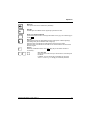
The following symbols are used in this manual:
!
i
indicates information which is important for your health or for preventing
physical damage.
indicates important information which is required to use the system properly.
►
Texts which follow this symbol describe activities that must be performed in
the order shown.
This font
indicates programme names, commands, or menu items.
"Quotation marks"
indicate names of chapters, data carriers, and terms that are being
emphasised.
2
A26361-K994-Z220-1-7619, Edition 2
Important notes
In this chapter you will find information regarding safety which it is essential to take note of when
working with your device.
Safety notes
!
Pay attention to the information provided in the "Safety" manual and in the following safety
notes.
During installation and before operating the device, please observe the instructions on
environmental conditions in the "Technical data" chapter as well as the instructions in the
"Preparing for use" chapter.
The ON/OFF switch does not disconnect the device from the mains voltage. To completely
disconnect the mains voltage, remove the power plug from the power socket.
The lithium battery on the mainboard should only be replaced in accordance with the
instructions in the "Extensions to the mainboard" - "Changing lithium battery" chapter.
Caution, components in the system can get very hot.
Transporting the device
!
Transport all parts separately in their original packaging or in a packaging which protects
them from knocks and jolts, to the new site. Do not unpack them until all transportation
manoeuvres are completed.
Cleaning the device
!
Turn off all power and equipment switches and disconnect the power plug from the mains
outlet.
Do not clean any interior parts yourself, leave this job to a service technician.
Do not use any cleaning agents that contain abrasives or may corrode plastic.
Ensure that no liquid enters the system.
Wipe the casing with a dry cloth. If particularly dirty, use a cloth that has been moistened in mild
domestic detergent and then carefully wrung out. Use disinfectant wipes to clean the keyboard and
the mouse.
A26361-K994-Z220-1-7619, Edition 2
3
Important notes
Energy saving, disposal and recycling
Further information on these topics can be found on the "Drivers & Utilities" DVD.
CE mark
CE mark for devices without radio component
The shipped version of this device complies with the requirements of the EC
Guidelines 2004/108/EC "Electromagnetic compatibility" and 2006/95/EC "Low
voltage directive".
4
A26361-K994-Z220-1-7619, Edition 2
Important notes
FCC Class B Compliance Statement
The following statement applies to the products covered in this manual, unless otherwise specified
herein. The statement for other products will appear in the accompanying documentation.
NOTE:
This equipment has been tested and found to comply with the limits for a "Class B" digital device,
pursuant to Part 15 of the FCC rules and meets all requirements of the Canadian InterferenceCausing Equipment Standard ICES-003 for digital apparatus. These limits are designed to provide
reasonable protection against harmful interference in a residential installation. This equipment
generates, uses and can radiate radio frequency energy and, if not installed and used in strict
accordance with the instructions, may cause harmful interference to radio communications. However,
there is no guarantee that interference will not occur in a particular installation. If this equipment does
cause harmful interference to radio or television reception, which can be determined by turning the
equipment off and on, the user is encouraged to try to correct the interference by one or more of the
following measures:
●
Reorient or relocate the receiving antenna.
●
Increase the separation between equipment and the receiver.
●
Connect the equipment into an outlet on a circuit different from that to which the receiver is
connected.
●
Consult the dealer or an experienced radio/TV technician for help.
Fujitsu Technology Solutions GmbH is not responsible for any radio or television interference caused
by unauthorized modifications of this equipment or the substitution or attachment of connecting
cables and equipment other than those specified by Fujitsu Technology Solutions GmbH. The
correction of interferences caused by such unauthorized modification, substitution or attachment will
be the responsibility of the user.
The use of shielded I/O cables is required when connecting this equipment to any and all optional
peripheral or host devices. Failure to do so may violate FCC and ICES rules.
A26361-K994-Z220-1-7619, Edition 2
5
Important notes
6
A26361-K994-Z220-1-7619, Edition 2
Preparing for use
!
Please observe the safety information in the "Important notes" chapter.
Unpacking and checking the delivery
It is recommended not to throw away the original packaging material! It may be required for
reshipment at some later date.
►
Unpack all the individual parts.
►
Check the delivery for damage incurred during transportation.
►
Check whether the delivery agrees with the details in the delivery note.
Should you discover that the delivery does not correspond to the delivery note, notify your local sales
outlet immediately.
Steps for initial setup
Only a few steps are necessary to put your new device into operation for the first time:
●
Select location for device and set up device
●
External devices, connecting
●
Check the voltage at the mains outlet and connect the device to an electrical outlet
●
Switching the device on
You will learn more about the individual steps in the following sections.
External devices
i
If you have received other devices in addition to your device (e.g. a printer or a modem),
do not connect these until after the initial installation. The following sections contain a
description of how to connect these external devices.
Drives and boards
i
If you have received drives or boards with your device, please do not install them until
after first-time setup. How to install drives and boards is described in the "System
upgrades" chapter.
A26361-K994-Z220-1-7619, Edition 2
7
Preparing for use
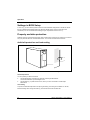
Setting up the device
!
When installing your device, give consideration to the safety notes in the "Safety" manual.
The device should only be set up in the intended orientation, i.e. in a vertical position.
We recommend that you place your device on a surface with good anti-slip qualities. In
view of the multitude of different finishes and varnishes used on furniture, it is possible that
the feet of the device will mark the surface they stand on.
Do not expose the device to extreme environmental conditions (see "Technical data").
Protect the device from dust, humidity, and heat.
Make sure that the device is adequately ventilated. In order to avoid overheating, do not
cover the ventilation area of the monitor or the device.
Depending on the location of your device, bothersome vibrations and noises may occur.
To prevent this, a distance of at least 10 mm should be maintained from other devices on
casing sides without ventilation surfaces. In addition, we recommend placing the device on
support feet, as these buffer vibrations.
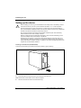
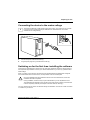
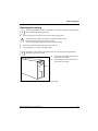
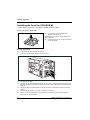
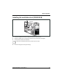
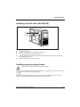
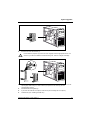
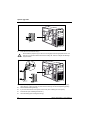
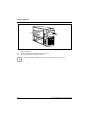
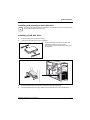
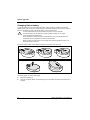
Screwing on the base foot (CELSIUS R6xx)
To ensure a secure stance, the base foot must be screwed on prior to start-up.
2
2
1
►
Lift the device slightly at the rear.
►
Push the base foot under the device in the direction of the arrow (1).
Make sure that the screw holes for the screws are aligned.
►
8
Screw on the base foot with the knurled screws (2).
A26361-K994-Z220-1-7619, Edition 2
Preparing for use
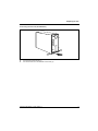
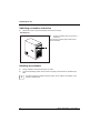
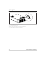
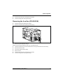
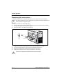
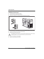
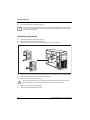
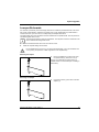
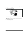
Unscrewing the base foot (CELSIUS R6xx)
1
►
Unscrew the knurled screws (1).
►
Pull off the base foot in the direction of the arrow (2).
A26361-K994-Z220-1-7619, Edition 2
1
2
9
Preparing for use
Connecting external devices
!
Read the documentation on the external device before connecting it.
With the exception of USB devices, always remove all power plugs before connecting
external devices!
Do not connect or disconnect cables during a thunderstorm.
Always take hold of the actual plug. Never unplug a cable by pulling the cable itself.
Connect and disconnect the cables in the order described below.
Connecting cables
►
Turn off all power and equipment switches.
►
Remove all power plugs from the grounded mains outlets.
►
Plug all cables into the device and peripherals. You must observe the information provided in
the "Important notes" chapter.
►
Plug all data communication cables into the utility sockets.
►
Plug all power cables into the grounded mains outlets.
Disconnecting cables
►
Turn off all power and equipment switches.
►
Remove all power plugs from the grounded mains outlets.
►
Unplug all data communication cables from the utility sockets.
►
Unplug all cables from the device and peripherals.
i
USB devices are hot-pluggable. This means you can connect and disconnect USB cables
while your device is switched on.
Additional information can be found in the "Connecting external devices to the USB ports"
section and in the documentation for the USB devices.
10
A26361-K994-Z220-1-7619, Edition 2
Preparing for use
Ports provided by the device
The connections are located on the front and back of the device. The ports available on your device
depend on the configuration level you have selected. The standard ports are marked with the
symbols shown below (or similar). Detailed information on the location of the connections is provided
in the manual for the mainboard.
Keyboard port, purple
Parallel port/Printer, burgundy
2
1
Serial port 1, teal or turquoise
Serial port 2, teal or turquoise
Monitor port, blue
Microphone jack (mono), pink
Headphones port, orange or light
Audio input (Line in), light blue
green
e-SATA port
Audio output (Line out), light green
i
USB - Universal Serial Bus, black
LAN
LAN port
PS/2 mouse port, green
1394
FireWire™, grey
Some of the connected devices require special drivers (see the documentation for the
connected device).
Connecting the monitor
►
Follow the instructions contained in the monitor manual to prepare the monitor for operation
(e.g. connecting cables).
►
Plug the data cable into the monitor port of the device.
►
Plug the monitor power cable into the grounded mains outlet.
A26361-K994-Z220-1-7619, Edition 2
11
Preparing for use
Connecting the mouse
Depending on the equipment level selected, your device will be supplied with a PS/2 mouse or a
USB mouse.
Connecting PS/2 mouse
►
Connect the PS/2 mouse to the PS/2 mouse port of the device.
Connecting USB mouse
►
Connect the USB mouse to the USB port of the device.
i
If you do not attach a mouse at the PS/2 mouse port, you can disable the mouse controller
in the BIOS Setup in order to free the IRQ12 for a different application.
Connecting the keyboard
Depending on the equipment level selected, your device will be supplied with a standard keyboard or
a USB keyboard.
Connecting standard keyboard
Use the supplied keyboard cable only.
►
Plug the rectangular connector of the keyboard cable into the rectangular socket on the
underside or on the rear of the keyboard.
►
Plug the round plug of the keyboard cable into the keyboard port on the device.
Connecting USB keyboard
Use the supplied keyboard cable only.
►
Plug the rectangular connector of the keyboard cable into the socket on the underside or on the
rear of the keyboard.
►
Insert the flat rectangular USB plug of the keyboard cable into a USB port of the device.
12
A26361-K994-Z220-1-7619, Edition 2
Preparing for use
Connecting external devices to the serial port
External devices (e.g. a printer or modem) can be connected to the serial port.
►
Connect the data cable to the external device.
►
Connect the data cable to the serial port.
Port settings
i
You can change the port settings (e.g. address, interrupt) in the BIOS Setup.
Device drivers
i
The devices connected to the parallel or serial port require drivers. Your operating system
already includes many drivers. If the required drive is missing, install it. Current drivers are
usually available on the Internet or will be supplied on a data carrier.
Connecting external devices to the USB ports
You can connect a wide range of external devices to the USB ports (e.g. printer, scanner, modem or
keyboard).
i
USB devices are hot-pluggable. This means you can connect and disconnect devices
while your operating system is running.
Additional information can be found in the documentation for the USB devices.
►
Connect the data cable to the external device.
►
Connect the data cable to a USB port .
Device drivers
i
The devices you connect to the USB ports usually require no driver of their own, as the
required software is already included in the operating system. However, if the USB device
requires its own software, please install it from the data carrier provided with the USB
device.
To ensure USB 2.0, only a 3 m long cable may be used from the front USB port to the
USB peripheral device.
A26361-K994-Z220-1-7619, Edition 2
13
Preparing for use
Connecting external devices to the FireWire port
External devices such as digital audio/video devices or other high-speed devices can be connected
to the FireWire port. The FireWire port operates at a speed of up to 400 Mbit per second.
i
FireWire devices are hot-pluggable. Therefore, the cables of FireWire devices can be
connected and disconnected with the system switched on.
Additional information is provided in the documentation of the FireWire devices.
►
Connect this data cable of the external devices to the FireWire port of the device.
►
Plug the power cable of the external device into a grounded mains outlet.
Connecting an external e-SATA device to the e-SATA port
You can connect further devices (e.g. an external hard disk) to e-SATA ports.
i
The CELSIUS R6xx is equipped as standard with an e-SATA port. On the CELSIUS M4xx
and R5xx, an adapter cable must be used, which is available as an option.
AHCI mode must be activated in the mainboard BIOS. In the preset factory default state,
this mode is activated as standard. For additional information on this topic, please refer to
the mainboard manual.
e-SATA devices are hot-pluggable. This means that the cables of e-SATA devices can be
connected and disconnected with the system switched on.
For further information please refer to the documentation for the e-SATA devices.
►
On the CELSIUS M4xx and R5xx, configure the e-SATA port in the BIOS as described in the
mainboard manual.
►
Connect the e-SATA device with its associated mains adapter.
►
Plug the power cable of the external device into a grounded mains outlet.
►
Connect the data cable of the external device to the e-SATA port of the device.
i
14
Devices which you connect to an e-SATA port usually require no driver of their own, as the
required software is already included in the operating system. However, if the e-SATA
device requires its own software, please install it from the data carrier provided with the eSATA device.
A26361-K994-Z220-1-7619, Edition 2
Preparing for use
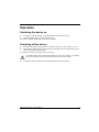
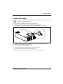
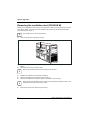
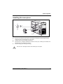
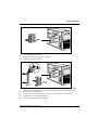
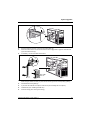
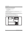
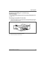
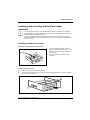
Connecting the device to the mains voltage
i
The device is fitted with a wide voltage range power supply. This means you do not need
to set the nominal voltage manually for these devices. Therefore there is no switch
available for the voltage setting.
1
►
Connect the power cable to the device (1).
►
Plug the power plug into a grounded mains outlet (2).
2
Switching on for the first time: installing the software
If the device is integrated into a network, the user and server details as well as the network protocol
are required during installation. Contact your network administrator if you have any questions about
these settings.
When you switch on the device for the first time, the supplied software is installed and configured.
Plan a reasonable amount of time for this, as this process must not be interrupted.
!
Once the installation has been started the device must not be switched off, unless the
installation has been completed.
During installation, the device may only be rebooted when you are requested to do so!
The installation will otherwise not be carried out correctly and the contents of the hard disk
must be completely restored (see chapter "Hard disk contents, restoring")
You may need the licence number for Windows during the installation. The licence number is located
on a sticker on your device.
A26361-K994-Z220-1-7619, Edition 2
15
Preparing for use
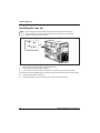
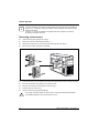
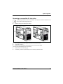
Switching on monitor and device
►
Switch the monitor on (see the operating manual for the monitor).
CELSIUS M / R
►
Press the ON/OFF switch on the front of
the device.
The power-on indicator glows white and the
device is started.
Installing the software
►
During installation, follow the instructions on screen.
►
Consult the operating system manual if there is anything unclear about the requested input
data.
i
16
You will find further information about the system, drivers, utilities, and updates on the
"Drivers & Utilities" DVD.
A26361-K994-Z220-1-7619, Edition 2
Operation
Switching the device on
►
If necessary, switch the monitor on (see the operating manual for the monitor).
►
Press the ON/OFF switch on the front of the device.
The power-on indicator glows white and the device is started.
Switching off the device
►
Shut down the operating system properly. In Windows: via the Start menu and the Exit function.
►
If the operating system does not automatically switch the device into an energy-saving mode or
switch it off, press the ON/OFF switch.
The device then consumes a minimum amount of energy.
!
►
The ON/OFF switch does not disconnect the device from the mains voltage. To completely
disconnect the mains voltage, remove the power plug from the power socket.
If necessary, switch the monitor off (see the operating manual for the monitor).
A26361-K994-Z220-1-7619, Edition 2
17
Operation
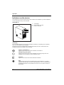
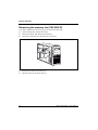
Indicators on the device
The indicators are on the front of the casing. Which indicators are available on your device depends
on the configuration level you have selected.
CELSIUS M / R:
1=
LCD-display
2 = Drive indicator, e.g. DVD
3 = Power-on indicator
1
2
3
LCD-display
The LCD-display lights up as soon as the workstation is switched on. Depending on the operating
state, up to ten symbols may be displayed.
During the boot process the BIOS status indicators (Postcodes) are shown. Please refer to the
mainboard manual for information on the Postcodes
Power on / workstation on
Appears on the LCD as soon as the workstation is switched on.
Standby/ Energy saving mode
Appears on the LCD as soon as the workstation is in energy saving mode. The
workstation can be switched on with the ON/OFF switch.
Hard disk
Appears on the LCD as soon as the hard disk is accessed.
X
18
Error
Appears on the LCD if there is a hardware error in the workstation or if a critical
hardware state arises (e.g. fan failure, high temperature). You can use DeskView to
get detailed information on the problem that occurred. If in any doubt, consult your
administrator.
A26361-K994-Z220-1-7619, Edition 2
Operation
LAN connection
Appears on the LCD as soon as the workstation is connected to a LAN.
LAN access
Appears on the LCD as soon as the workstation sends or receives data over the
LAN.
Message
When software that supports this function is used, the appearance of this symbol on
the display indicates that an incoming message (mail, fax) is waiting.
Appears on the LCD when an incoming message (mail, fax) is waiting. This symbol
only appears if you use software that supports this function.
Date
The current date and the calendar symbol are shown on the LCD.
USB
Appears on the LCD when a USB port was activated in the function USB Security in
BIOS and the device connected to this port is removed during operation. This
prevents another device from being connected.
The symbol disappears again after the system is rebooted.
Time
The current time and the time symbol are shown on the LCD.
Drive indicator, e.g. DVD
The indicator lights up when the CD-ROM or DVD drive of the device is accessed. You must never
under any circumstances remove the CD/DVD while the indicator is lit.
Power-on indicator
●
The indicator glows white:
The device is switched on.
i
●
The indicator flashes white:
The device is in energy-saving mode. After being switched on with the ON/OFF switch, the
device powers up or returns to the state it was in before it entered energy-saving mode.
!
●
The display can also glow white if the device has been switched off by holding
the ON/OFF switch pressed for an extended period of time (see
"Troubleshooting and tips").
In energy-saving mode the device must not be disconnected from the mains supply,
otherwise data loss may occur.
The indicator is not illuminated:
The device is switched off or is in hibernate mode. The device may be disconnected from the
mains supply.
A26361-K994-Z220-1-7619, Edition 2
19
Operation
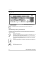
Keyboard
1
2
3
1=
2=
3=
i
Function keys
Power button (optional)
Alphanumeric keypad
4
4=
5=
5
Cursor keys
Numeric keypad (calculator keypad)
The illustrated keyboard is an example and may differ from the model you use.
Important keys and key combinations
The description of the following keys and key combinations applies to Microsoft operating systems.
Details of other keys and key combinations can be found in the documentation of the relevant
application programme.
ON/OFF switch (optional)
Depending on the setting in the BIOS Setup, the system can be switched on, off, or on
and off with this button. Some operating systems allow you to configure additional
functions of the ON/OFF switch in the Control Panel.
With some keyboards the ON/OFF switch can only be used with an ACPI (Advanced
Configuration and Power Management Interface). Otherwise the key is inoperative.
The mainboard must support this function.
Enter key
confirms the marked selection. The enter key is also referred to as the "Return" key.
Start key
calls up the Windows Start menu.
20
A26361-K994-Z220-1-7619, Edition 2
Operation
Menu key
calls up the menu for the marked item (Windows).
Shift key
enables upper-case letters and the upper key symbols to be used.
Alt Gr (e.g. German keyboard)
produces a character shown on the right-hand side of a key (e.g. the character @ on
the key Q ).
Alt Gr
Num key
Switches the numeric key pad between number mode ("Num" indicator lights up)
and editing mode ("Num" indicator does not light up).
When the Num Lock indicator is lit the digit and comma keys are active.
When the Num Lock indicator is not lit the cursor control functions are active in the
Numeric keypad.
Num
Ctrl key
Starts key combination actions. The Ctrl (Strg) key is also called "Control" or
"Control key".
Ctrl
Ctrl
+
Alt
+
Del
Ctrl + Alt + Del
Call up the menu with which you can shut down, lock and logout
the device.
In addition, you can use this key combination to call up the
Windows Task-Manager or change your Windows password.
A26361-K994-Z220-1-7619, Edition 2
21
Operation
Settings in BIOS Setup
In BIOS Setup you can set the system functions and the hardware configuration of the device. When
the PC is delivered, the default entries are valid (see "BIOS Setup" manual or manual for the
mainboard). You can customise these settings to your requirements in the BIOS Setup.
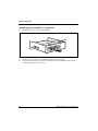
Property and data protection
Software functions and mechanical locking offer a broad range of functions for protecting your device
and your personal data from unauthorised access. You can also combine these functions.
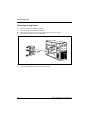
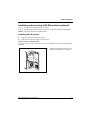
Anti-theft protection and lead-sealing
1
2
1=
Holes for padlock
2=
Device for "Kensington Lock"
Anti-theft protection
You can protect your device from theft.
●
●
with the Kensington Lock device (2) and with a Kensington MicroSaver.
Consult the manual for your Kensington Lock.
with the holes (1), a padlock and a chain, which you have connected to a fixed object
beforehand.
Lead-sealing
To prevent unauthorised persons from opening the casing, the casing can be sealed. To do this,
feed the sealing chain through the holes (1) and seal the chain with the lead seal.
22
A26361-K994-Z220-1-7619, Edition 2
Operation
BIOS setup security functions
The Security menu in BIOS Setup offers you various options for protecting your personal data against
unauthorised access, e.g.:
●
●
●
●
●
Preventing unauthorised access to the BIOS Setup.
Preventing unauthorised system access
Virus warnings, activating
BIOS: Protecting BIOS from overwriting
Protecting the device from being switched on by an external device
You can also combine these functions.
You will find a detailed description of the Security menus and how to assign passwords in the manual
for the mainboard or in the "BIOS Setup" manual.
Access authorisation via SmartCard (optional)
In systems equipped with a SmartCard reader, access can be restricted to those users who have a
corresponding SmartCard.
Access protection with SystemLock (optional)
With SystemLock you can protect your system from unauthorised booting. Then a system can only be
booted when the user inserts a valid SmartCard in the SmartCard reader and enters his/her personal
code number (PIN). To use SystemLock you require the following components:
●
External or internal SmartCard reader
●
SystemLock installed (see "BIOS Setup" manual)
●
SmartCard
SystemLock controls access to your device. When a SmartCard is initialised, permissions are
assigned for system access (system, setup, system+setup, admin). You can configure several
SmartCards for one system and initialise them with different permissions. In addition you can protect
access to your hard disk.
In this way users can be divided into user groups. Users of a user group use SmartCards with the
same permissions.
More information on SystemLock
i
If you also want to use other security software in addition to SystemLock (e.g.
SMARTY), please read the documentation on your security software beforehand.
A26361-K994-Z220-1-7619, Edition 2
23
Operation
SystemLock permissions
You can initialise a SmartCard with one of the following permissions:
System
The system starts following entry of the user PIN. You can change the user PIN.
Setup
You can open and change the BIOS Setup and change the user PIN.
System+Setup
The system starts following entry of the user PIN. You can open and change the
BIOS Setup and change the user PIN.
Admin
The system starts following entry of the user PIN. You can change the user PIN
an the administrator PIN, unlock locked SmartCards, open and change the
BIOS Setup and generate additional SmartCards for this system.
For instructions on how to install and operate SystemLock, and how to initialise SmartCards, see the
"BIOS Setup" manual.
Operating the SmartCard reader
●
Operating the internal SmartCard reader
Depending on the configuration level, the device can be switched on by inserting your SmartCard. If
the SmartCard reader has been released, the SmartCard reader indicator on the front of the device
lights green.
●
Operating the external SmartCard reader
After the device is switched on, you will be prompted to insert your SmartCard.
24
A26361-K994-Z220-1-7619, Edition 2
Troubleshooting and tips
!
Refer to the safety notes in the "Safety" manual and in the "Preparing for use" chapter
when connecting or disconnecting cables.
If a fault occurs, try to correct it as described in the following places:
●
●
●
●
in this chapter
in the documentation of the connected devices
in the help systems of the software used
in the documentation of your operating system
If you fail to correct the problem, proceed as follows:
►
Switch the device off.
►
Make a note of the steps and the circumstances that led to the fault.
►
Make a note of any error messages displayed.
►
Note the ID number of your device. The Ident-No. can be found on the type rating plate on the
back of the casing.
►
Contact your sales outlet or our customer service centre.
Help if problems occur
Should you ever have a problem with your computer that you cannot solve yourself, in many cases
you can solve it quickly using the SystemDiagnostics program pre-installed on your computer.
►
To start the SystemDiagnostics program, click Start - Programs - Fujitsu - SystemDiagnostics.
►
If a problem is detected during the test run, the SystemDiagnostics program outputs a code (e.g.
DIFS code YXXX123456789123).
►
Take a note of this DIFS code and the ID number of your device. The ID number can be found
on the type rating plate on the back of the casing.
►
If you still need assistance resolving the problem, contact the relevant Help Desk for your
country (see the Help Desk List or go to http://ts.fujitsu.com/support). Have the ID/serial No. of
your system and the DIFS code ready.
A26361-K994-Z220-1-7619, Edition 2
25
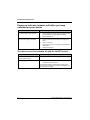
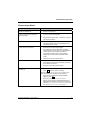
Troubleshooting and tips
Power-on indicator remains unlit after you have
switched on your device
Cause
Troubleshooting
The mains voltage supply is faulty.
►
Check whether the power cable is plugged properly
into the device and a grounded mains outlet.
►
Switch the device on.
►
Pull the power plug of the device out of the mains
outlet.
►
Wait for a moment.
►
Plug the power plug into a properly grounded mains
outlet again.
►
Switch the device on.
Internal power supply overloaded.
The device cannot be switched off with the ON/OFF switch
Cause
Troubleshooting
The device has not been switched on
with the ON/OFF switch.
►
Press the ON/OFF switch again.
System crash
►
Press the ON/OFF switch for at least 4 seconds,
until the device switches off.
The operating system is not shut-down properly in the
process. Error messages are therefore possible the next
time the system is booted.
26
A26361-K994-Z220-1-7619, Edition 2
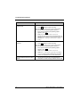
Troubleshooting and tips
Screen stays blank
Cause
Troubleshooting
Monitor is switched off.
►
Switch your monitor on.
Power saving has been activated
(screen is blank)
►
Press any key on the keyboard.
or
►
Deactivate the screen saver. If necessary, enter the
appropriate password.
Brightness control is set to dark
►
Adjust the brightness control. For detailed
information, please refer to the operating manual
supplied with your monitor.
Power cable not connected
►
Switch off the monitor and the device.
►
Check that the monitor power cable is properly
connected to the monitor and to a grounded mains
outlet or to the monitor socket of the device.
►
Check that the device power cable is properly
plugged into the device and a grounded mains
outlet.
►
Switch on the monitor and the device.
►
Switch off the monitor and the device.
►
Check that the monitor cable is properly connected
to the device and monitor.
►
Switch on the monitor and the device.
Monitor cable not connected
Wrong monitor has been set under
Window XP
►
Restart the device.
►
Press F8 while the system is booting.
Either the Windows Advanced Start Options menu or the
menu for selecting the operating system appears.
A26361-K994-Z220-1-7619, Edition 2
►
If the menu for selecting the operating system
appears, press F8 .
►
Select Safe Mode or Safe Mode with Network.
►
Set the correct values for the attached monitor as
described in the operating manual of the monitor by
selecting Start - Settings - Control Panel - Display and
then the Appearance, Themes, Settings tabs.
27
Troubleshooting and tips
Cause
Troubleshooting
Wrong setting for the monitor under
Windows Vista
►
Restart the device.
►
Press F8 while the system is booting.
Either the Windows Advanced Start Options menu or the
menu for selecting the operating system appears.
►
Wrong setting for the monitor under
Windows 7
If the menu for selecting the operating system
appears, press F8 .
►
Select Safe Mode or Safe Mode with Network .
►
Set the correct values for the connected monitor, as
described in the operating manual of the monitor, by
selecting Start - (Settings) - Control Panel - Display Settings.
►
Restart the device.
►
Press F8 while the system is booting.
Either the Windows Advanced Start Options menu or the
menu for selecting the operating system appears.
►
The wrong RAM modules have been
inserted
28
If the menu for selecting the operating system
appears, press F8 .
►
Select Safe Mode or Safe Mode with Network .
►
Select Start - Control Panel - Appearance and Themes Display to set the correct values for the connected
monitor, as explained in the monitor instructions.
►
See the technical manual for the mainboard for
information on which memory modules can be used.
A26361-K994-Z220-1-7619, Edition 2
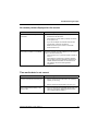
Troubleshooting and tips
No mouse pointer displayed on the screen
Cause
Troubleshooting
The mouse is not correctly
connected.
►
Shut down the operating system properly.
►
Schalten Sie das Gerät aus.
►
Check that the mouse cable is properly connected
to the system unit.
If you use an adapter or extension lead with the
mouse cable, check the connections.
The mouse controller is not enabled.
►
Make sure that only one mouse is connected.
►
Switch the device on.
The mouse controller must be enabled if you use a PS/2
mouse on the PS/2 mouse port.
►
Check in the BIOS Setup that the mouse controller is
Enabled.
►
Check that the mouse driver is properly installed
and is present when the application programme is
started. Detailed information can be found in the
user guide for the mouse and application
programme.
Time and/or date is not correct
Cause
Troubleshooting
The time and date are incorrectly set.
►
Set the correct time and date within the operating
system you are using.
or
The on-board backup battery in the
device is flat.
A26361-K994-Z220-1-7619, Edition 2
►
Set the correct time and/or date in the BIOS Setup.
►
If the time and date are repeatedly wrong when you
switch on your device, replace the lithium battery
(see "Changing lithium battery".)
29
Troubleshooting and tips
Error messages on the screen
Error messages and their explanation are contained:
●
●
in the technical manual for the mainboard
in the documentation for the programmes used
Installing new software
When installing programmes or drivers, important files may be overwritten and modified. To be able
to access the original data in the event of any problems following installation, you should backup
your hard disk prior to installation.
Restoring hard disk contents
i
The factory default settings are restored using the recovery DVD and the "Drivers &
Utilities" DVD.
On the sleeve of the recovery DVD you will find the instructions for restoring the contents of the hard
disk.
Tips
Topic
Tip
Out of system resources
If you have too many applications running at once, you
may experience problems due to a lack of system
resources.
►
Close unnecessary applications.
Or
►
Other manuals
30
Run the applications in a different order.
Other manuals are provided as PDF files on the "Drivers
& Utilities" DVD.
A26361-K994-Z220-1-7619, Edition 2
System upgrades
i
The devices are very similar to each other. Therefore, often only the CELSIUS R is shown
in the following illustrations. In case of differences, this will be pointed out at the
appropriate point.
As the device has to be shut down in order to install/deinstall system hardware
components, it is a good idea to print out the relevant sections of this chapter.
It may be necessary to update the BIOS when carrying out a system expansion or
hardware upgrade. Additional information is contained in the "BIOS Setup" manual or
possibly in the technical manual for the mainboard.
When installing components that become very hot, make sure that the maximum
permissible temperature is not exceeded.
!
The device must be switched off when installing/removing the system expansions and may
not be in the energy-saving mode.
Remove the power plug before opening the device.
This chapter describes all the activities required to modify your device hardware (e.g. installing
boards or drives).
Read the supplied documentation before installing new drives and/or boards.
Refer to the technical manual for the mainboard before making any extensions to the mainboard.
A26361-K994-Z220-1-7619, Edition 2
31
System upgrades
Information about boards
Take care with the locking mechanisms (catches and centring pins) when you are replacing boards
or components on boards.
To prevent damage to the board or the components and conductors on it, please take care when you
insert or remove boards. Make sure expansion boards are inserted straight.
Never use sharp objects (screwdrivers) for leverage.
Boards with electrostatic sensitive devices (ESD) are identifiable by the label
shown.
When you handle boards fitted with ESDs, you must, under all
circumstances, observe the following points:
●
You must always discharge static build up (e.g. by touching a
grounded object) before working.
●
The equipment and tools you use must be free of static charges.
●
Always hold boards with ESDs by their edges.
●
Never touch pins or conductors on boards fitted with ESDs.
Touchpoints for easier installation and removal of modules
and components
In order to make the installation and removal of modules and components easier, the locations for
engaging and releasing them are green coloured or marked with green dots (Touchpoints).
!
32
Always release and engage the modules and components marked in this way at the
corresponding locations and in the direction shown in the relevant chapter of this manual.
A26361-K994-Z220-1-7619, Edition 2
System upgrades
Opening the casing
i
►
The following illustrations show the CELSIUS R. The sequence of actions is identical for all
device variants and configuration levels.
Switch the device off. The device must not be in energy-saving mode!
!
Please observe the safety information in the chapter "Important notes".
Disconnect the power plug from the mains outlet.
Only re-insert the power plug after you have closed the casing.
►
Remove any connected cables that obstruct you at the unit.
►
Place the device in a convenient working position.
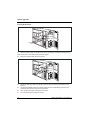
i
The location of the screws for the transport lock can vary from the following illustration
depending on the device variant.
►
Remove the two transport lock screws (1)
on the back of the casing.
►
Undo the safety screws of the side cover
on the back of the casing.
1
►
Lay the device on its side on a stable, flat and clean surface.
A26361-K994-Z220-1-7619, Edition 2
33
System upgrades
1
2
3
►
Turn the key in the direction of the arrow (1).
►
Press the clip upwards (2).
The side cover is now free from the clip and can be detached.
►
34
Pull the side cover away from the casing (3).
A26361-K994-Z220-1-7619, Edition 2
System upgrades
Closing the casing
i
The following illustration show the CELSIUS R. The sequence of actions is identical for all
device variants and configuration levels.
►
Lay the device on its side on a stable, flat and clean surface.
►
Hook the side cover into the cutouts in the upper and lower guide rails.
Pay attention that the lugs of the lock fit into the associated retainers on the casing.
3
2
1
►
Slide the side cover in the direction of the arrow (1) until it is heard to engage in the clip.
►
Press the clip in the direction of the arrow (2).
►
Turn the key in the direction of the arrow (3).
►
Secure the safety screws of the side cover on the back of the casing.
►
Return the device to the place where you require to use it.
►
Reconnect any disconnected cables (power cord, cables to external devices, etc.).
A26361-K994-Z220-1-7619, Edition 2
35
System upgrades
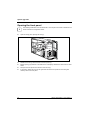
Opening the front panel
i
►
The following illustrations show the CELSIUS R. The sequence of actions is identical for all
device variants and configuration levels.
Open the casing (see “Opening the casing”).
1
1
1
2
►
Release the three lugs at the left side of the front panel (1).
►
Before opening, pay attention to the cable of the LCD display. Release the cable from the cable
holder.
►
Fold open the front panel in the direction of the arrow (2).
►
If necessary, detach the hinge on the right-hand side of the front panel from the casing and
carefully remove the front panel.
36
A26361-K994-Z220-1-7619, Edition 2
System upgrades
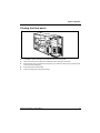
Closing the front panel
2
2
2
1
►
If necessary, hook in the hinge on the right-hand side of the front panel.
►
Take care not to trap the cable of the LCD display when closing the front panel.
►
Close the front panel in the direction of the arrow (1) so that the three lugs on the left-hand side
of the front panel engage (2).
►
Fit the cable into the cable holder.
►
Close the casing (see "Closing the casing").
A26361-K994-Z220-1-7619, Edition 2
37
System upgrades
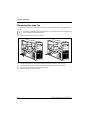
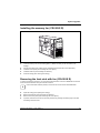
Removing the side fan
You will need to remove the side fan inside the casing in order to install boards or upgrade the main
memory.
i
►
The following illustrations show the CELSIUS R. The sequence of actions is identical for all
device variants and configuration levels.
Open the casing (see "Opening the casing").
2
a
1
►
Release the side fan by pressing the locking hook (a) in the direction of the arrow (1).
►
Pull the bottom edge of the side fan in the direction of the arrow (2) out of the casing.
►
Disconnect the cable of the fan from the mainboard.
►
Remove the side fan from the casing.
38
A26361-K994-Z220-1-7619, Edition 2
System upgrades
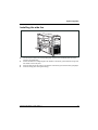
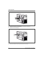
Installing the side fan
1
2
a
►
Connect the fan cable to the corresponding plug contact on the mainboard (refer also to the
manual of the mainboard).
►
Position the side fan at a slight angle in the direction of the arrow (1) and hook the fan lugs into
the cutouts on the cross piece.
►
Press the side fan into the casing in the direction of the arrow (2) so that the catch (a) engages.
►
Close the casing (see "Closing the casing").
A26361-K994-Z220-1-7619, Edition 2
39
System upgrades
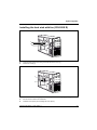
Installing the front fan (CELSIUS M)
You must install a front fan when converting the hard disks to SAS hard disks.
Securing front fan on fan bracket
►
1
Lay the fan on the fan bracket in the
direction of the arrow (1).
When doing so, ensure the proper rotating and
air-flow direction.
►
Press the fan firmly into the fan bracket until
it is felt to engage.
Installing the front fan
►
Open the casing (see "Opening the casing").
►
Open the front panel (see "Opening the front panel").
1
2
►
Connect the fan cable.
►
Insert the fan into the casing in the direction of the arrow (1) so that the lower edge of the fan is
flush with the bottom of the device. Make sure that the power supply cable is not pinched when
doing so.
►
Slightly pull back the green expansion rivet (2) until the tip of the expansion rivet is no longer
spread.
►
Press the green expansion rivet (2) into the hole on the casing.
►
Secure the fan by pressing the green expansion rivet (2) into the casing until the tip of the
expansion rivet is spread again.
40
A26361-K994-Z220-1-7619, Edition 2
System upgrades
►
Close the front panel (see "Closing the front panel").
►
Close the casing (see "Closing the casing").
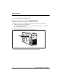
Removing the front fan (CELSIUS M)
►
Open the casing (see "Opening the casing").
►
Open the front panel (see "Opening the front panel").
2
►
1
Detach the green expansion rivet (1).
Make sure that the green expansion rivet (1) is not pulled off the fan.
►
Tilt the fan toward the front in the direction of the arrow (2) and remove it from the casing.
►
Disconnect the fan cable.
►
Pull the fan cable out of the casing.
►
Remove the fan.
►
Close the front panel (see "Closing the front panel").
►
Close the casing (see "Closing the casing").
A26361-K994-Z220-1-7619, Edition 2
41
System upgrades
Removing the ventilation duct (CELSIUS M)
Before you can upgrade the main memory or the processor, or before you can replace the processor
or the lithium battery, you must remove the ventilation duct and the rear fan located underneath it
(see “Removing the rear fan ”).
i
►
The ventilation duct is connected to the fan.
Open the casing (see "Opening the casing").
a
2
1
►
If there are any expansion cards in slots 6 and 7, remove them (see "Installing and removing a
board").
►
Disconnect the memory cooling fan cable.
i
Refer to the mainboard manual for the location of the fan cable.
►
Release the ventilation duct at the lever marked (a).
►
Slide the ventilation duct in the direction of the arrow (1).
►
Remove the ventilation duct from the casing in the direction of the arrow (2).
i
►
42
When removing the ventilation duct, be careful not to damage the processor cooler on the
mainboard or the cable of the memory cooler.
Remove the rear fan (see "Removing the rear fan").
A26361-K994-Z220-1-7619, Edition 2
System upgrades
Removing the rear fan
►
Remove the ventilation duct (see "Removing the ventilation duct (CELSIUS M)").
1
1
1
1
2
a
►
Press the lever (a) in the direction of the arrow until the lever unhooks.
The hooks (1) on the back of the casing release.
►
Carefully unhook the hooks (1).
►
Remove the rear fan from the casing in the direction of the arrow (2).
A26361-K994-Z220-1-7619, Edition 2
43
System upgrades
Installing the rear fan
i
When routing the fan cable, make sure that it cannot become kinked or trapped.
When inserting the rear fan and the ventilation duct, be careful not to damage the
processor cooler(s) on the mainboard.
a
a
2
2
a
a
2
b
3
2
1
►
Insert the rear fan into the casing in the direction of the arrow (1). When doing so, the hooks (a)
must hook into the openings (2) in the back of the casing.
►
Push bothersome cables aside if necessary.
►
Press the rear fan into the casing in the direction of the arrow (3) until it is felt to engage.
The rear fan is properly engaged when the locking lug (b) protrudes slightly at the back of the casing.
►
Connect the fan cable to the rear fan.
►
Install the ventilation duct (see "Installing the ventilation duct (CELSIUS M)").
44
A26361-K994-Z220-1-7619, Edition 2
System upgrades
Installing the ventilation duct (CELSIUS M)
a
1
2
►
Insert the ventilation duct into the casing in the direction of the arrow (1).
►
Slide the ventilation duct in the direction of the arrow (2) until the lever (a) engages.
►
Connect the fan cable to the mainboard.
i
►
Refer to the mainboard manual for the location of the fan cable.
Close the casing (see "Closing the casing").
A26361-K994-Z220-1-7619, Edition 2
45
System upgrades
Removing the cross-piece
To upgrade the main memory or replace the processor you will need to remove the cross-piece.
i
The following illustrations show the CELSIUS R. The sequence of actions is identical for all
device variants and configuration levels.
►
Open the casing (see "Opening the casing").
►
CELSIUS M only: Remove the ventilation duct and the rear fan (see "Removing the ventilation
duct (CELSIUS M)" and "Removing the rear fan").
►
Remove the side fan (see "Removing the side fan").
b
b
2
a
1
►
Grasp the cross-piece by the lug (a) and unhook it from the brackets in the casing.
►
Pull the cross-piece slightly out of the casing in the direction of the arrow (1).
►
Detach the cross-piece from the brackets (b) on the back of the casing.
►
Remove the cross-piece from the casing in the direction of the arrow (2).
!
46
Take care not to damage the cables when removing the cross-piece.
A26361-K994-Z220-1-7619, Edition 2
System upgrades
Installing the cross-piece
a
a
c
2
1
2
b
►
Insert the cross-piece at a slight angle into its brackets (a) on the back of the casing.
►
Press the cross-piece into the casing in the direction of the arrow (1) until the lugs (b) of the
cross-piece hook into the brackets (c) in the casing.
►
Install the side fan (see "Installing the side fan").
►
CELSIUS M only: Install the ventilation duct and the rear fan (see "Installing the ventilation duct
(CELSIUS M)" and "Installing the rear fan").
►
Close the casing (see "Closing the casing").
!
Take care not to damage the cables when installing the cross-piece.
A26361-K994-Z220-1-7619, Edition 2
47
System upgrades
Removing the memory fan (CELSIUS R)
To be able to upgrade the main memory, you must remove the memory fan.
►
Open the casing (see "Opening the casing").
►
Remove the side fan (see "Removing the side fan").
►
Remove the cross-piece (see "Removing the cross-piece").
1
►
Disconnect the cables at the memory fan.
►
Take the memory fan out of the casing (1).
48
A26361-K994-Z220-1-7619, Edition 2
System upgrades
Installing the memory fan (CELSIUS R)
1
►
Insert the memory fan into the holding plate (1). Make sure that you feel the memory fan
engage.
►
Connect the memory fan cables on the mainboard (see the manual for the mainboard).
►
Install the cross-piece (see "Installing the cross-piece").
►
Install the side fan (see "Installing the side fan").
►
Close the casing (see "Closing the casing").
Removing the heat sink with fan (CELSIUS R)
In order to change the processor, you must remove the heat sink. There is an additional fan secured
at the rear of the heat sink and you must also remove it.
i
If there is another heat sink present, remove this too in the manner described below.
►
Open the casing (see "Opening the casing").
►
Remove the side fan (see "Removing the side fan").
►
Remove the cross-piece (see "Removing the cross-piece").
►
If present, remove the fan duct on the front processor by pressing the locking lugs to the side
and taking out the fan duct.
A26361-K994-Z220-1-7619, Edition 2
49
System upgrades
1
a
2
a
1
►
Disconnect the cables of the processor fan.
►
Release the locking lugs (a) of the fan bracket in the direction of the arrow (1).
►
Take the fan out of the casing (2).
1 1
1 1
2
►
Undo the screws (1).
►
Remove the heat sink from the casing in the direction of the arrow (2).
50
A26361-K994-Z220-1-7619, Edition 2
System upgrades
Installing the heat sink with fan (CELSIUS R)
2 2
1
2 2
►
Insert the heat sink into the casing in the direction of the arrow (1).
►
Fasten the screws (2).
a
1
a
►
Insert the fan into the casing (1). Make sure that you feel the locking lugs (a) engage.
►
Connect the fan cable to the mainboard.
►
Install the cross-piece (see "Installing the cross-piece").
A26361-K994-Z220-1-7619, Edition 2
51
System upgrades
►
Install the side fan (see "Installing the side fan").
►
Close the casing (see "Closing the casing").
Removing the heat sink (CELSIUS M)
To upgrade the main memory or replace the processor you will need to remove the heat sink.
►
Open the casing (see "Opening the casing").
►
Remove the ventilation duct and the rear fan (see "Removing the ventilation duct (CELSIUS
M)" and "Removing the rear fan").
►
Remove the side fan (see "Removing the side fan").
►
Remove the cross-piece (see "Removing the cross-piece").
1 1
1 1
2
►
Undo the screws (1).
►
Remove the heat sink from the casing in the direction of the arrow (2).
52
A26361-K994-Z220-1-7619, Edition 2
System upgrades
Installing the heat sink (CELSIUS M)
2
2
2 2
1
►
Insert the heat sink into the casing in the direction of the arrow (1).
►
Fasten the screws (2).
►
Install the cross-piece (see "Installing the cross-piece").
►
Install the side fan (see "Installing the side fan").
►
Install the ventilation duct and the rear fan (see "Installing the ventilation duct (CELSIUS M)"
and "Installing the rear fan").
►
Close the casing (see "Closing the casing").
Installing and removing a board
!
i
Please take note of the section "Information about boards".
The following illustrations show the CELSIUS R. The sequence of actions is identical for all
device variants and configuration levels.
The number, position and arrangement of the board slots on the mainboard can be found in the
manual for the mainboard. Boards may already be installed on shipment.
A26361-K994-Z220-1-7619, Edition 2
53
System upgrades
Installing a short board
►
Open the casing (see "Opening the casing").
►
Remove the fan (see "Removing the side fan").
►
Remove the cross-piece if it is in the way (see "Removing the cross-piece ”).
1
2
1
3
►
Press on the clips (1) in the direction of the arrow and unhook them from the casing rear panel.
►
Fold open the locking rail in the direction of the arrow (2).
►
Remove the slot cover from the slot (3).
!
Do not dispose of the slot cover. For cooling, protection against fire and in order to comply
with EMC regulations, you must refit the slot cover if you remove the board.
►
Take the new board out of its packaging.
►
Make the required settings for the board.
54
A26361-K994-Z220-1-7619, Edition 2
System upgrades
1
►
Push the board into the slot (1).
►
Press the board into the slot so that it engages.
►
If necessary, connect the cables.
a
2
3
2
►
Press the clips (2) from outside in the cut-outs on the case rear panel until the clips engage.
When doing so, make sure that you press the rail carrier (a) into the corresponding opening.
►
Fold closed the locking slide (3).
►
If you have removed the cross-piece, install it now (see "Installing the cross-piece").
►
Install the fan (see "Installing the side fan").
►
Close the casing (see "Closing the casing").
A26361-K994-Z220-1-7619, Edition 2
55
System upgrades
i
If you have installed or removed a PCI board, please check the relevant PCI slot settings in
the BIOS Setup. If necessary, change the settings. Further information is provided in the PCI
board documentation.
The slots 1, 3, 5 and 7 are suitable for low-profile cards with an adapter. The slots are
counted from the bottom to the top.
Removing a short board
►
Open the casing (see "Opening the casing").
►
Remove the fan (see "Removing the side fan").
►
Remove the cross-piece if it is in the way (see "Removing the cross-piece ”).
►
Disconnect the cables connected to the board.
1
2
1
3
►
Press on the clips (1) in the direction of the arrow and unhook them from the casing rear panel.
►
If the board in question is a graphics card, undo the catch.
►
Fold open the locking rail in the direction of the arrow (2).
►
Pull the board out of the slot (3).
►
Place the board into appropriate packaging.
!
56
For cooling, protection against fire, and in order to comply with EMC (electromagnetic
compatibility) regulations, you must refit the slot cover.
A26361-K994-Z220-1-7619, Edition 2
System upgrades
a
1
►
Push the slot cover into the slot (1).
Ensure that the projection (a) on the slot cover engages into the appropriate recess. If it
does not, you will find it difficult to close the locking rail. There is a danger of damage.
!
b
2
3
2
►
Press the clips (2) from outside, pressing through the cut-outs on the case rear panel until the
clips engage. When doing so, make sure that you press the rail carrier (b) into the
corresponding opening.
►
Fold closed the locking slide (3).
►
If you have removed the cross-piece, install it now (see "Installing the cross-piece").
►
Install the fan (see "Installing the side fan").
A26361-K994-Z220-1-7619, Edition 2
57
System upgrades
►
Close the casing (see "Closing the casing").
i
If you have installed or removed a PCI board, please check the relevant PCI slot settings
in the BIOS Setup. If necessary, change the settings. Further information is provided in the
PCI board documentation.
Installing a long board
►
Open the casing (see "Opening the casing").
►
Remove the fan (see "Removing the side fan").
►
Remove the cross-piece if it is in the way (see "Removing the cross-piece").
1
2
1
3
►
Press on the clips (1) in the direction of the arrow and unhook them from the casing rear panel.
►
Fold open the locking rail in the direction of the arrow (2).
►
Remove the slot cover from the slot (3).
!
Do not discard the slot cover. For cooling, protection against fire and in order to comply
with EMC regulations, you must refit the slot cover if you remove the board.
►
Take the new board out of its packaging.
►
Make the required settings for the board.
58
A26361-K994-Z220-1-7619, Edition 2
System upgrades
a
1
2
1
2
1
1
►
Push the board into the slot (1) and into the board holder (2).
►
Press the board into the slot so that the board is felt to engage and on graphic cards the lever
(a) on the board closes (2).
►
If necessary, connect the cables to the board.
b
1
2
1
►
Press the clips (1) from outside in the cut-outs on the case rear panel until the clips engage.
When doing so, make sure that you press the rail carrier (a) into the corresponding opening.
►
Fold closed the locking slide (2).
►
If you have removed the cross-piece, install it now (see "Installing the cross-piece").
►
Install the fan (see "Installing the side fan").
►
Close the casing (see "Closing the casing").
A26361-K994-Z220-1-7619, Edition 2
59
System upgrades
Removing a long board
►
Open the casing (see "Opening the casing").
►
Remove the fan (see "Removing the side fan").
►
Remove the cross-piece if it is in the way (see "Removing the cross-piece").
►
Disconnect the cables connected to the board.
1
2
1
2
►
Press on the clips (1) in the direction of the arrow and unhook them from the casing rear panel.
►
Fold open the locking rail in the direction of the arrow (2).
60
A26361-K994-Z220-1-7619, Edition 2
System upgrades
1
2
►
a
At the same time release the board from the board holder (a) by pressing the clip on the board
holder in the direction of the arrow (1) and pulling the board in the direction of the arrow (2).
b
2
1
1
2
2
1
►
Release the lever (b) by pulling it in the direction of the arrow (1).
►
Release the board from the board holder by pulling the board in the direction of the arrow (2).
►
Place the board in suitable packaging.
!
For cooling, protection against fire, and in order to comply with EMC (electromagnetic
compatibility) regulations, you must refit the slot cover.
A26361-K994-Z220-1-7619, Edition 2
61
System upgrades
a
1
►
Push the slot cover into the slot (1).
Ensure that the projection (a) on the slot cover engages into the appropriate recess. If it
does not, you will find it difficult to close the locking rail. There is a danger that damage
may be caused.
!
b
2
3
2
►
Press the clips (2) from outside in the cut-outs on the case rear panel until the clips engage.
When doing so, make sure that you press the rail carrier (b) into the corresponding opening.
►
Fold closed the locking slide (3).
►
If you have removed the cross-piece, install it now (see "Installing the cross-piece").
►
Install the fan (see "Installing the side fan").
►
Close the casing (see "Closing the casing").
62
A26361-K994-Z220-1-7619, Edition 2
System upgrades
Low-profile boards
For units with a particularly low overall height, there are so-called low-profile boards with a slot cover
with a lower overall height to match the low-profile units. To also install these low-profile boards in
normal board slots, you must mount a corresponding slot adapter beforehand
Two-piece board slot covers are fitted to the slots intended for low-profile boards. The two pieces are
connected together with a screw.
i
The following illustrations show the CELSIUS R. The sequence of actions is identical for all
device variants and configuration levels.
►
Remove the desired board slot cover and undo the screw.
►
Make the required settings for the board.
!
Do not dispose of the slot cover. If you remove the board again, you must reinstall the slot
cover (cooling, fire protection or EMC regulations to be complied with).
Mounting slot adapter
►
1
Fit the slot adapter on the slot cover of the
low-profile board (1) and screw it on (2).
Now you can install the low-profile board in a
suitable slot like a normal board (see "Installing a
short board").
2
Removing slot adapter
►
Unscrew the screw (1) and remove the slot
adapter (2).
2
1
A26361-K994-Z220-1-7619, Edition 2
63
System upgrades
Installing and removing drives
The casing can accommodate a total of seven drives:
●
three accessible drives
(two 5¼ inch drives and one 3½ inch drive)
●
four non-accessible drives
(3½ inch drives)
"Accessible drives" are for instance DVD drives or multi-card readers into which a data medium can
be inserted from outside. "Non-accessible drives" are for example hard disk drives.
Serial ATA drives and SAS drives
You can install S-ATA drives or SAS drives (Serial Attached SCSI drives) in your device. S-ATA
drives are supported by default (refer also to the manual for the mainboard). Mixed equipment is also
possible. When simultaneously installing S-ATA hard disks and SAS hard disks, you must ensure the
proper assignment of the cables to the corresponding connectors.
The internal wiring of your device is shown in the following wiring diagrams.
Wiring diagram for S-ATA drives or SAS drives
Blu-Ray / DVD-RW /
DVD
DVD-RW / DVD
DVD-RW / DVD /
FD
USB-Device
HD 1
HD 2
SATA / SAS
HD 3
HD 4
64
A26361-K994-Z220-1-7619, Edition 2
System upgrades
Removing an accessible 5¼ inch drive
The following illustrations show the CELSIUS R. The sequence of actions is identical for all
device variants and configuration levels.
i
►
Open the casing (see "Opening the casing").
2
1
1
►
Pull the data and the power supply connectors from the desired drive.
►
Loosen the screws (1).
►
Slide the drive out of the bay in the direction of the arrow (2) from behind.
3
The drive now protrudes slightly out of the casing.
►
Slide the drive out of the casing (3).
►
If necessary, make the required settings on the remaining hard disk drives.
A26361-K994-Z220-1-7619, Edition 2
65
System upgrades
2
2
1
►
If you are not installing a new drive, slide the empty slide-in insert into the casing until it
noticeably engages.
►
Secure the empty slide-in module with the screws (2).
►
Close the casing (see "Closing the casing").
i
66
It may be necessary to modify the entry for the remaining drives in the BIOS Setup.
A26361-K994-Z220-1-7619, Edition 2
System upgrades
Installing an accessible 5¼ inch drive
►
Open the casing (see "Opening the casing").
1
►
1
2
If a Weight Saver is present, remove this first: Remove the screws (1) and pull the Weight
Saver out of the casing (2).
!
Do not discard the Weight Saver. For cooling, protection against fire, and in order to
comply with EMC regulations, you must refit the Weight Saver if you remove the drive
again later.
►
Take the new drive out of its packaging.
►
Make the required settings on the drive.
A26361-K994-Z220-1-7619, Edition 2
67
System upgrades
2
2
1
►
Slide the accessible drive into the casing as far as the stop (1).
►
Fasten the drive into place with the screws (2).
►
Plug the data and the power supply connectors into the drive. Make sure the polarity is correct.
►
Close the casing (see "Closing the casing").
i
68
It may be necessary to modify the entry for the drive in the BIOS Setup.
A26361-K994-Z220-1-7619, Edition 2
System upgrades
Removing and installing a 3 ½ inch drive (e.g.
MultiCard reader)
i
A carrier is needed to install a 3½ inch drive in a 5 ¼ inch bay. When this carrier is used,
the 3½ inch drive can be installed in the 5¼ inch bay instead of the Weight Saver or a 5¼
inch drive.
Removing an accessible 3½ inch drive
►
Remove the carrier with the 3½ inch drive in the same way as an accessible 5¼ inch drive (see
"Installing an accessible 5¼ inch drive"). When you do so, make sure to re-install the Weight
Saver if you do not install a new drive.
1
2
1
►
Remove the screws (1) on both sides of the carrier.
►
Pull the 3½ inch drive out of the carrier (2).
A26361-K994-Z220-1-7619, Edition 2
2
69
System upgrades
Installing an accessible 3½ inch drive
►
Take the new 3½ inch drive out of its packaging.
2
2
►
Slide the 3½ inch drive into the carrier (1).
►
Secure the 3½ inch drive on both sides of the carrier using the screws (2).
►
Install the carrier with the 3½ inch drive in the same way as an accessible 5¼ inch drive (see
"Installing an accessible 5¼ inch drive").
70
A26361-K994-Z220-1-7619, Edition 2
System upgrades
Installing and removing a hard disk drive
i
The following illustrations show the CELSIUS R. The sequence of actions is identical for all
device variants and configuration levels.
Installing a hard disk drive
►
Open the casing (see "Opening the casing").
►
Take the new hard disk drive out of its packaging.
►
a
Secure the EasyChange rails on the side of the
hard disk by inserting the pins (a) of the
EasyChange rail in the corresponding holes (b) of
the hard disk.
b
►
Push the hard disk drive into the casing until the EasyChange rails engage.
►
Connect the data and power supply cables to the hard disk drive or to the hard disk drives.
A26361-K994-Z220-1-7619, Edition 2
71
System upgrades
Removing a hard disk drive
►
Open the casing (see "Opening the casing").
1
2
1
►
Press the EasyChange rails in the direction of the arrows (1).
►
Pull the hard disk drive out of the carrier (2).
i
72
►
Pull the EasyChange rails off the hard disk
drive.
►
If necessary, make the required settings on
the remaining hard disk drive.
►
Close the casing (see "Closing the casing").
It may be necessary to modify the entry for the drive in the BIOS Setup.
A26361-K994-Z220-1-7619, Edition 2
System upgrades
Installing and removing a SmartCard reader
(optional)
i
You can operate a maximum of 2 internal USB components in your device. An adapter
cable (available as an option) will be needed for the second internal USB component (e.g.
a WLAN module or a MultiCard reader).
A carrier is needed to install a SmartCard reader in a 5¼ inch bay. When this carrier is
used, the SmartCard reader can be installed in the 5¼ inch bay instead of a Weight Saver
or a 5¼ inch drive.
Installing a SmartCard reader
Screw the SmartCard reader onto the carrier
►
Push the SmartCard reader - with the
component side facing downwards - in the
direction of the arrow (1) into the guide of
the carrier (a).
►
Secure the SmartCard reader with the
screws (2).
2
2
a
a 1
Installing SmartCard reader
►
Open the casing (see "Opening the casing").
►
If there is a Weight Saver in the 5¼ inch bay, remove it as described in the chapter "Installing
an accessible 5¼ inch drive".
2
2
A26361-K994-Z220-1-7619, Edition 2
1
73
System upgrades
►
Side the carrier with SmartCard reader into the module for the SmartCard reader (1).
►
Fasten the carrier with the screws (2) on both sides of the slide-in module.
►
Install the module with the SmartCard reader in the same way as an accessible 5¼ inch drive
(see "Installing an accessible 5¼ inch drive").
Removing a SmartCard reader
►
Remove the module with the SmartCard reader in the same way as an accessible 5¼ inch
drive (see "Removing an accessible 5¼ inch drive"). When you do so, make sure to re-install
the Weight Saver if you do not install a new drive.
1
2
1
2
►
Remove the screws on both sides of the slide-in module (1).
►
Slide the SmartCard reader out of the module (2).
74
A26361-K994-Z220-1-7619, Edition 2
System upgrades
Installing and removing a WLAN module (optional)
i
You can install a WLAN module in your device.
The following illustrations show the CELSIUS R. The sequence of actions is identical for
all device variants and configuration levels.
Installing WLAN module
►
Open the casing (see "Opening the casing").
►
Open the front panel (see "Opening the front panel").
Initial installation of a WLAN module
The slot on the WLAN module inside of the front panel is protected by a metal cover when the device
is shipped.
►
A26361-K994-Z220-1-7619, Edition 2
Break the pre-stamped metal cover out of
the WLAN opening using a screwdriver.
75
System upgrades
Installing WLAN module
1
2
►
2
Slide the WLAN module into the slot on the front of the casing in the direction of the arrow (1).
Make sure that the screw holes for the screws are aligned.
►
Fasten the WLAN module with the screws (2).
1
►
Thread the USB data cable of the WLAN module through the opening in the direction of the
arrow (1).
►
Connect the USB data cable of the WLAN module onto the corresponding connector on the
mainboard (also see the manual for the mainboard).
►
Close the front panel (see "Closing the front panel").
►
Close the casing (see "Closing the casing").
76
A26361-K994-Z220-1-7619, Edition 2
System upgrades
i
More detailed information on the use of Wireless LAN can be found in the "Wireless LAN"
manual.
This manual is provided as PDF file on the "Drivers & Utilities" DVD.
Removing WLAN module
►
Open the casing (see "Opening the casing").
►
Open the front panel (see "Opening the front panel").
2
1
1
►
Loosen the screws (1).
►
Pull the WLAN module out of the bay the direction of the arrow (2).
►
Close the front panel (see "Closing the front panel").
►
Close the casing (see "Closing the casing").
A26361-K994-Z220-1-7619, Edition 2
77
System upgrades
Extensions to the mainboard
Details on how you can upgrade the main memory or the processor of your device are provided in
the manual for the mainboard.
Upgrading main memory (CELSIUS R)
►
Open the casing (see "Opening the casing").
►
If present, remove the side fan and the cross-piece (see "Removing the side fan" and
"Removing the cross-piece").
►
Remove the memory fan (see "Removing the memory fan (CELSIUS R)").
►
Upgrade the main memory according to the description in the manual for the mainboard.
►
Reinstall the memory fan (see “Installing the memory fan (CELSIUS R)").
►
Install the cross-piece and the side fan (see "Installing the cross-piece" and "Installing the side
fan").
►
Close the casing (see "Closing the casing").
Upgrading main memory (CELSIUS M)
►
Open the casing (see "Opening the casing").
►
Remove the ventilation duct (see "Removing the ventilation duct (CELSIUS M)").
►
Upgrade the main memory according to the description in the manual for the mainboard.
►
Reinstall the ventilation duct (see "Installing the ventilation duct (CELSIUS M)").
►
Close the casing (see "Closing the casing").
78
A26361-K994-Z220-1-7619, Edition 2
System upgrades
Replacing the processor
►
Open the casing (see "Opening the casing").
►
Remove the ventilation duct (see "Removing the ventilation duct (CELSIUS M)").
►
Remove the side fan (see "Removing the side fan").
►
Remove the cross-piece (see "Removing the cross-piece").
►
CELSIUS M only: Remove the heat sink (see "Removing the heat sink (CELSIUS M)").
►
CELSIUS R only: Remove the heat sink with fan (see "Removing the heat sink with fan
(CELSIUS R)”).
►
Upgrade the processor according to the description in the manual for the mainboard.
►
CELSIUS R only: Install the heat sink with fan (see "Installing the heat sink with fan (CELSIUS
R)”).
►
CELSIUS M only: Install the heat sink (see "Installing the heat sink (CELSIUS M)").
►
Install the cross-piece (see "Installing the cross-piece").
►
Install the side fan (see "Installing the side fan").
►
Install the ventilation duct (see "Installing the ventilation duct (CELSIUS M)").
►
Close the casing (see "Closing the casing").
A26361-K994-Z220-1-7619, Edition 2
79
System upgrades
Changing lithium battery
In order to permanently save the system information, a lithium battery is installed to provide the
CMOS-memory with a current. A corresponding error message notifies the user when the charge is
too low or the battery is empty. The lithium battery must then be replaced.
!
Incorrect replacement of the lithium battery may lead to a risk of explosion!
The lithium battery may be replaced only with an identical battery or with a type
recommended by the manufacturer.
Do not throw lithium batteries into the household waste. They must be disposed of in
accordance with local regulations concerning special waste.
Make sure that you observe the correct polarity when replacing the lithium battery. The
plus pole must be on the top!
The lithium battery holder exists in different designs that function in the same way.
3
2
2
3
1
►
Press the catch in the direction of the arrow (1).
The battery jumps out of the holder slightly.
►
Remove the battery (2).
►
Push the new lithium battery of the identical type into the holder and press it downward until it
engages.
80
A26361-K994-Z220-1-7619, Edition 2
Technical data
Technical data
Electrical data
Regulations complied with:
EN 60950
UL 60950
CSA 22.2 No.950
Protection class:
I
Rated voltage range:
100 V - 240 V
Rated frequency:
50 Hz - 60 Hz
Max. rated current (CELSIUS M):
100 V – 127 V : 6 A
200 V – 240 V : 3 A
or:
100 V – 127 V : 9 A
Max. rated current (CELSIUS R5XX):
100 V – 127 V : 9 A
200 V – 240 V : 4 A
200 V – 240 V : 4 A
or:
100 V – 127 V : 12 A
200 V – 240 V : 6 A
Max. rated current (CELSIUS R6XX):
100 V – 127 V : 12 A
200 V – 240 V : 6 A
Dimensions
Width/Depth/Height (CELSIUS M / R5xx):
215 mm/520 mm/446 mm
Width/Depth/Height (CELSIUS V / R640):
215 mm/620 mm/446 mm
Weight
in basic configuration (CELSIUS M / R5xx):
approx. 24 kg
in basic configuration (CELSIUS V / R640):
approx. 26 kg
Environmental conditions
Environment class (3K2)
EC 721 part 3-3
Environment class (2K2)
IEC 721 part 3-2
Temperature
Operating (3K2)
15°C .... 35°C
Transport (2K2)
-25°C .... 60°C
Condensation in operating must be avoided.
Clearance required to ensure adequate ventilation:
without air vents
min. 10 mm
with air vents
min. 200 mm
A26361-K994-Z220-1-7619, Edition 2
81
Technical data
i
82
The data sheets of these devices contains further technical data. You will find the data
sheets on the internet at http://ts.fujitsu.com/support.
A26361-K994-Z220-1-7619, Edition 2
Index
3
3 1/2-inch drive 64
3½ inch
installing 70
removing 69
5
5 1/4-inch drive 64
A
Access permission, SmartCard 23
Accessible drive
installing 67
removing 65
Alphanumeric keypad 20
Anti-theft protection 22
ATA drive, serial 64
Audio devices, connecting 14
Audio input 11
Audio output 11
B
Base foot
screwing on 8
unscrewing 9
Battery 80
BIOS setup
settings 22
BIOS Setup 22
configuration 22
security functions 23
system settings 22
Board 32
installing 53, 54
removing 53, 56
Button
ON/OFF switch 20
C
Cable
connecting 10
disconnecting 10
Case
opening 33
Casing
lead-sealing 22
CD-ROM drive
indicator 19
CD-ROM indicator 19
CE mark 4
A26361-K994-Z220-1-7619, Edition 2
Chain 22
Closing front panel 37
Connecting
device 15
keyboard 12
mouse 12
PS/2 mouse 12
standard keyboard 12
USB keyboard 12
Connecting FireWire devices 14
Connecting standard keyboard 12
Contents of delivery 7
Cross-piece 78
Cross-piece, installing 47
Crosspiece, removing 46
Ctrl+Alt+Del 21
Cursor keys 20
D
Data protection 22
Date
not correct 29
Device
Anti-theft protection 22
cannot boot 26
checking rated voltage 15
cleaning 3
connecting 15
Extensions 31
indicators 18
lead-sealing 22
opening 33
ports 11
setting up 8
switching off 17
switching on 16, 17
transporting 3
Device drivers
parallel port 13
serial port 13
Devices
connecting 13
Disposal 4
Drive 64
accessible 64
installing 67
non-accessible drive 64
removing 65
DVD drive
indicator 19
DVD indicator 19
83
Index
E
Electromagnetic compatibility 4
EMC, Electromagnetic compatibility 63
Energy saving 4
Ergonomic, video workstation 8
Error
date 29
device 26
mouse 29
screen 27
time 29
Error message 30
e-SATA connection 11
ESD 32
Extensions
Device 31
mainboard 78
External devices
connecting 13
ports 11
F
FireWire 11
FireWire port 14
Function keys 20
H
Hard disk contents, restoring 30
Hard disk drive
installing 64, 71
version A 71
removing 64
version A 72
replacing 71
Headphones 11
I
Important notes 3
Indicators
device 18
Installation
new software 30
software 15, 16
switching on for the first time 15
Installation of components
Touchpoint 32
Installing front fan (CELSIUS M) 40
Interfaces 11
K
Kensington Lock 22
Key
Alt Gr 21
Control 21
84
Ctrl 21
cursor keys 20
Enter 20
enter key 20
Num 21
Return 20
Shift 21
Key combination 20, 21
Keyboard 20
alphanumeric keypad 20
cursor keys 20
function keys 20
numeric keypad 20
port 12
Keyboard port 11
Keyboard, connecting 12
Keys 20
Ctrl key 21
Ctrl+Alt+Del 21
Menu key 21
Shift key 21
Start key 20
L
LAN port 11
LCD 18
Lead-sealing 22
Line in 11
Line out 11
Lithium battery 78
replacing 80
Low voltage directive 4
Low-profile boards 63
mounting slot adapter 63
removing slot adapter 63
M
Main memory 78
upgrade 78
Mainboard, extensions 78
Manuals, further 30
Memory
insufficient 30
not enough 30
Microphone jack 11
Monitor
connecting 11
switching off 17
switching on 16, 17
transporting 3
Monitor port 11
Mouse
connecting 12
error 29
Mouse Cursor 29
A26361-K994-Z220-1-7619, Edition 2
Index
Mouse port 11
N
New installation, software 30
Notational conventions 2
Note
boards 32
Notes
CE mark 4
disposal 4
energy saving 4
important 3
recycling 4
safety 3
Numeric keypad 20
O
ON/OFF switch 17, 20
Opening front panel 36
Operation 17
Other manuals 30
P
Packing material 7
unpacking 7
Parallel port 11, 13
Connecting devices 13
settings 13
Port
e-SATA 11
Power-on indicator 17, 19
dark 26
does not glow 19
glows white 19
Power-on LED
fails to light 26
Preparing for first use, overview 7
Preparing for use 7
overview 7
Printer 11
Processor 78
Processor, replacing 79
Property protection 22
PS/2 mouse
connecting 12
port 12
PS/2 mouse port 11
R
Ready-to-operate 17
Recycling 4
Removal of components
Touchpoint 32
Removing front fan (CELSIUS M) 41
A26361-K994-Z220-1-7619, Edition 2
Replacing
lithium battery 80
Retransportation 3
S
Safety notes 3
SAS-Drives 64
Screen
no screen display 27
stays blank 27
SCSI drive 64
Securing front fan on fan bracket 40
Security functions
BIOS setup 23
SmartCard 23
SmartLock 23
Security measures 22
serial ATA drive 64
Serial Attached SCSI-Drive 64
Serial port 11, 13
Connecting devices 13
settings 13
Setup see BIOS Setup
Side fan
installation 39
removal 38
Signs and symbols 2
SmartCard reader 73
installing 73
installing or removing 73
operating 24
removing 73, 74
Software
installation 16
installing 15
new installation 30
Summer time 29
System expansion 31
System settings
BIOS Setup 22
T
Time
not correct 29
Time, daylight savings 29
Tips 25, 30
Touchpoint 32
Transport 3
Trouble
device 26
mouse 29
screen 27
Troubleshooting 25
85
Index
U
USB
Universal Serial Bus 11
USB devices
connecting 13
USB port 12
connecting devices 13
connecting keyboard 12
connecting mouse 12
86
V
Ventilation 8
Video devices, connecting 14
Video workstation 8
W
Warm boot 21
WLAN module
installing 75
removing 77
removing and installing 75
A26361-K994-Z220-1-7619, Edition 2