1
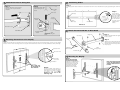
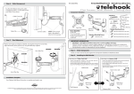
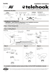
Installation Instructions
G Fix the Tilt angle of the Display
TM
Step 1
-5° to 25°
Tilt
Fit two M8x45mm Locking screws
into brackets behind Display. Adjust
the Tilt angle of the Display. Tighten
two locking screws with the Long
6mm Allen Key provided.
M8 Small
Washer
Tighten
M8x45mm
Screw
WARNING: Do not attempt to
adjust tilt angle without firstly
loosening locking screws.
Doing so may damage
product.
Flat Screen Wall Mount | Swing Arm
Telehook Flat Screen
Wall Mount Swing Arm
supports a maximum
weight of 65kgs (143lbs)
Component Checklist
IMPORTANT:
Ensure you have received all parts against the component checklist prior to installing.
NOTE:
Wall Mount Bracket (Right)
The manufacturer does
not accept responsibility
for incorrect installation.
Clinch Nuts
Slider (x2)
Long 6mm
Allen Key
Wall Mount
Cover
Wall Mount Bracket (Left)
Telehook Swing Arm
Pivot Head
Wall Mount Horizontal Bar
TOOLS REQUIRED:
Power Drill
z 12mm (1/2”) Drill Bit
z 7mm (9/32”) Drill Bit
z Adjustable wrench
z
Bit Box
H Horizontal Adjustment Feature
I Security Option
For added security, you may
choose to attach a padlock
to one or both brackets to
prevent theft of the display.
It is recommended that the
padlock should have a
shackle diameter of 5mm
(3/16”).
LOOSEN
ADJUST
ANGLE
M12 x80mm
Screw
8mm
Allen Key
TIGHTEN
If necessary, once the display is mounted, adjust the horizontal
angle as shown.
M8 Small
M8 x45mm
M8 x45mm
M10 Steel M10 Coach Wall Plug (x4)
Locking Screws (x2) Washer (x2) Button Screws (x2)
Washer (x4) Screw (x4)
Padlock
(not supplied)
5mm (3/16”)
diameter shackle
M12 Steel
Washer
Long 6mm
Allen Key
M12 Plastic
Washer (x2)
Multi
M12
Cable Manager
Washer (x6)
Locking Nut
Clip (x4)
5mm M8 x16mm M6 x16mm M5 x16mm M4 x16mm
Mounting
Mounting
Allen Key Mounting
Mounting
Screws (x6) Screws (x6) Screws (x6) Screws (x6)
A Attach Telehook Swing Arm Unit to the Wall
Masonry Wall
Timber Stud Wall
12mm (1/2”) hole
7mm (9/32”) hole
M10 Coach Screw
M10 Coach Screw
Tip: Use a Spirit
Level to ensure
this surface is
vertical.
.
Tip: Use a Spirit
Level to ensure
this surface is
vertical.
OR
.
Wall Plug
M10 Steel Washer
No portion of this document or any artwork contained herein should be reproduced in any way without the express written consent of Atdec Pty Ltd.
Due to continuing product development, the manufacturer reserves the right to alter specifications without notice. Published: 29.08.08 c
Timber Stud
M10 Steel Washer
B Attach Pivot Head to Swing Arm
D
Positioning Sliders
Step 1
Step 1
Step 2
Slide the Wall Mount Cover along the
Swing Arm until it snap fits onto the
wall plate.
Assemble the Pivot Head
onto the Swing Arm as
shown.
Accurately position sliders at distance X as recorded in Section A. Ensure the Sliders are equally spaced along the centre Horizontal
Bar.
8mm Allen
Key
=
=
Step 2
M12 Screw
Tighten
Slider (x2)
End of
Swing Arm
M12 Plastic
Washer
Grub
Screws (x2)
Horizontal Bar
Secure slider in
position and tighten
firmly with supplied
Allen Key. Ensure that
it locates into the slot
on the horizontal bar.
The grub screw should
tighten flush to
surface.
Distance X
Wall Mount Cover
Wall Plate
E Attach the Horizontal Bar to Pivot Head
M12 Steel
Washer
M12
Locking Nut
Pivot Head
Step 1
Swing Arm
Attach the Horizontal Bar and tighten
screws as shown.
5mm Allen
Key
C Attaching the Brackets to the Display
Step 2
Attach the four Cable Manager Clips to
the Swing Arm by inserting the clips into
the holes. Ensure that the clips are held
firmly in place.
Step 1
Attach left and right wall mount brackets to the rear of your display. Select M4, M5, M6 or M8 mounting screws to suit your display.
Ensure a minimum of two mounting screws are used per wall mount bracket. Clinch nuts must be positioned as shown (internally).
=
=
M8 Screw Hole
M8x45mm
Button Screws
Horizontal Bar
M6 Screw Hole
TOP
F Mounting the Display
M5 & M4
Screw Hole
Multi Washer
Clinch Nuts
Note: make sure
the threaded nut
faces inwards
X
Cable
Manager Clips
Step 2:
Use the supplied Multi Washer as
shown above. Ensure that the tightest
fitting hole in the washer is used for
the specific sized screw. Note
distance X, for use in the
following steps.
Step 1
Note: This operation
requires two persons.
Now that the horizontal bar is
attached to the Swing Arm
with the Sliders in place, lift
the Display with brackets
attached and hook the
Brackets over the Sliders.
Note: The brackets should
rest on the horizontal bar
with the slider between the
bracket.