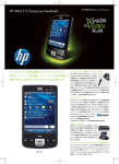
1
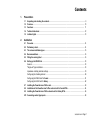
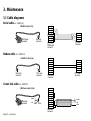
www.mgeups.com
MGE UPS SYSTEMS
PowerServicesTM
TelPac
Installation manual
Phone
JBUS / RS485
Settings
A 5V B R+ R- T+ T-
CD
UPS
PowerServices TelPac
Phone
JBUS / RS485
Settings
CD
A 5V B R+ R- T+ T-
UPS
T H E
U N I N T E R R U P T I B L E
P O W E R
PowerServices TelPac
P R O V I D E R
34003602EN/AB
- Page 1
Page 2 - 34003602EN/AB
Introduction
Thank you for selecting an MGE UPS SYSTEMS product to protect your electrical equipment.
PowerServices TelPac has been designed with the utmost care.
It comes in 2 versions: card (ref. 66096) or external (ref. 66097 or 66098).
The card version can be installed by the customer or by an MGE UPS SYSTEMS After Sales Service technician.
The external version can only be installed by a specialised MGE UPS SYSTEMS After Sales Service technician.
We recommend you take time to read this manual to take full advantage of the many features of this product.
To discover the entire range of MGE UPS SYSTEMS products, visit our Web site at www.mgeups.com or contact your
nearest MGE UPS SYSTEMS representative.
Environment
MGE UPS SYSTEMS pays great attention to the environmental impact of its products during the design and manufacture
stages and through to the end of its life cycle.
◗ MGE UPS SYSTEMS products comply with the strictest regulations.
◗ They do not contain CFCs or HCFCs.
Recycling of packaging
Packaging has been designed to be recycled. Please make sure it is correctly recycled (in compliance with applicable
regulations).
Recycling of products at the end of their life cycle
MGE UPS SYSTEMS undertakes to recycle all recovered products at the end of their life cycle in installations complying
with applicable regulations. Please contact our sales office.
See the environment section on our Web site at www.mgeups.com.
Special precautions
◗
◗
If the card or external unit must be stored prior to installation, always store in a dry location.
Storage temperature range: -10ºC to +70ºC.
34003602EN/AB
- Page 3
Foreword
EMC compatibility
The PowerServices TelPac card and external versions comply with the following standards, on condition that they are
installed and used in compliance with their intended use and manufacturer’s instructions:
◗ Safety standards for IT equipment: EN 60950/A11 (1998).
◗ EMC:
EN 61000-6-2 (1999), EN 61000-6-3 (2002).
The PowerServices TelPac card and external versions comply with the following European directives:
Low voltage:
73/23/EEC and 93/68/EEC.
◗ EMC:
89/336/EEC and 93/68/EEC.
◗
Federal Communication Commission (FCC) statement
Part 15
This equipment has been tested and found to comply with the limits for a Class A digital device, pursuant to part 15 of the
FCC Rules. These limits are designed to provide reasonable protection against harmful interference when the equipment is
operated in a commercial environment. This equipment generates, uses, and can radiate radio frequency energy and, if not
installed and used in accordance with the instruction manual, may cause harmful interference to radio communications.
Operation of this equipment in a residential area is likely to cause harmful interference in which case the user will be
required to correct the interference at his own expense.
Part 68
This equipment has been tested and found to comply with the limits for a Class A digital device, pursuant to part 15 of the
FCC Rules.
Radio and Telecommunications compatibility
The PowerServices TelPac card and external versions comply with the European R&TTE directive, on condition that they
are installed and used in compliance with their intended use and manufacturer’s instructions.
Page 4 - 34003602EN/AB
Foreword
Modem compatibility and supported countries
The modem integrated in the PowerServices TelPac card is compatible with European standard CTR21 (01.98) in
accordance with Council Decision 98/482/EC.
List of countries supported by the modem
Australia
Austria
Belgium
Brazil
Bulgaria
Canada
China
Czechoslovakia
Denmark
Finland
France
Germany
Greece
Hong Kong
Hungary
India
Ireland
Israel
Italy
Japan
Korea
Luxembourg
Malaysia
Mexico
New Zealand
Netherlands
Norway
Philippines
Poland
Portugal
Russia
Singapore
South Africa
Spain
Sweden
Switzerland
Taiwan
United Kingdom
United States
34003602EN/AB
- Page 5
Foreword
Pictogram symbols
Important instructions that must always be followed.
Information and advice.
Visual indication.
Action.
UPS :
Uninterruptible Power System.
The conventions used to represent indicator lights in the illustrations are as follows:
Indicator off.
Indicator on.
Flashing Indicator.
Page 6 - 34003602EN/AB
Contents
1.
Presentation
1.1
1.2
1.3
1.4
1.5
2.
Unpacking and checking the contents .......................................................................................................... 9
Overview ......................................................................................................................................................... 10
Functions ...................................................................................................................................................... 11
Technical data sheet ....................................................................................................................................... 12
Indicator lights ................................................................................................................................................ 13
Installation
2.1
2.2
2.3
2.4
2.5
2.6
Procedure ........................................................................................................................................................ 14
Preliminary check ........................................................................................................................................... 14
The various installation types ....................................................................................................................... 15
Recommendations ......................................................................................................................................... 16
Fitting the warning label ................................................................................................................................ 16
Setting up the RS485 link .............................................................................................................................. 18
General ............................................................................................................................................................. 18
"Single-unit" type installation ............................................................................................................................ 18
Impedance matching and bias settings ............................................................................................................ 19
Configuring the shielding terminal .................................................................................................................... 20
Configuring the RS485 card for Comet ............................................................................................................ 21
Configuring the RAUZ card for Galaxy ............................................................................................................ 22
2.7 Installing the PowerServices TelPac card .................................................................................................... 23
2.8 Installation of the PowerServices TelPac external unit for Comet UPSs .................................................. 24
2.9 Installing the PowerServices TelPac external unit for Galaxy UPSs ......................................................... 26
2.10 Connecting contact type inputs .................................................................................................................... 28
34003602EN/AB
- Page 7
Contents
3.
Maintenance
3.1
Page 8 - 34003602EN/AB
Cable diagrams ............................................................................................................................................... 30
Serial cable diagrams (ref. 34003618) ............................................................................................................. 30
Modem cable (ref. 34003729) .......................................................................................................................... 30
Comet link cable (ref. 34003747) ..................................................................................................................... 30
1. Presentation
1.1 Unpacking and checking the contents
66096
www.mgeups.com
MGE UPS SYSTEMS
PowerServices
Telpac
Installation and user
manual
Phone
JBUS / RS485
Settings
A 5V B R+ R- T+ T-
CD
UPS
PowerServices TelPac
Phone
JBUS / RS485
Settings
A 5V B R+ R- T+ T-
CD
UPS
PowerServices TelPac
THE UNINTERRUPTIBLE POWER PROVIDER
F
G
MGE ATTENTION : Onduleur sous Teleservice
WARNING:
UPS: under
Teleservice
ATTENTION
Onduleur
sous Teleservice
MGE
WARNING:
UPS: under
Teleservice
ATTENTION
Onduleur
sous Teleservice
MGE
UPS SYSTEMS
UPS SYSTEMS
UPS SYSTEMS
Ne pas mettreWARNING:
hors tensionUPS
sansunder
avoir Teleservice
au préalable
arrêté
ligne
téléphonique
Ne la
pas
mettre
hors tension sans avoir au préalable
Do arrêté
notNe
switch
off
without
disconnecting
la
ligne
téléphonique
pas
mettre
horsfirst
tension
sans avoir au préalable
the Do
telephone
not switch
off without
first disconnecting
arrêté
laline
ligne
téléphonique
the Do
telephone
lineoff without first disconnecting
not switch
the telephone line
E
A
C
B
Phone
JBUS / RS485
Settings
D
Phone
A 5V B R+ R- T+ T-
CD
UPS
JBUS / RS485
Settings
A 5V B R+ R- T+ T-
CD
UPS
PowerServices TelPac
PowerServices TelPac
66097, 66098
www.mgeups.com
MGE UPS SYSTEMS
PowerServices
Telpac
Installation and user
manual
Phone
JBUS / RS485
Settings
A 5V B R+ R- T+ T-
CD
UPS
PowerServices TelPac
Phone
Settings
CD
UPS
JBUS / RS485
A 5V B R+ R- T+ T-
PowerServices TelPac
THE UNINTERRUPTIBLE POWER PROVIDER
F
G
MGE ATTENTION : Onduleur sous Teleservice
WARNING:
UPS: under
Teleservice
ATTENTION
Onduleur
sous Teleservice
MGE
WARNING:
UPS: under
Teleservice
ATTENTION
Onduleur
sous Teleservice
MGE
UPS SYSTEMS
UPS SYSTEMS
UPS SYSTEMS
Ne pas mettreWARNING:
hors tensionUPS
sansunder
avoir Teleservice
au préalable
arrêté
ligne
téléphonique
Ne la
pas
mettre
hors tension sans avoir au préalable
Do arrêté
notNe
switch
off
without
disconnecting
la
ligne
téléphonique
pas
mettre
horsfirst
tension
sans avoir au préalable
the Do
telephone
not switch
off without
first disconnecting
arrêté
laline
ligne
téléphonique
the Do
telephone
lineoff without first disconnecting
not switch
the telephone line
I
E
A
C
H
J
Phone
Settings
CD
D
UPS
JBUS / RS485
A 5V B R+ R- T+ T-
PowerServices TelPac
H
Content of the card version
A: PowerServices TelPac communication
card.
B: cover plate specifically designed for
Galaxy PW UPSs.
C: 5m telephone cable equipped with RJ11
plugs.
D: 2.5m serial communication cable used for
configuration and maintenance operations.
E: 3 warning labels.
F: this manual.
G: information form needed to activate
Teleservice.
Content of the external version
A: PowerServices TelPac external
communication unit with its fixing kit.
C: 5m telephone cable equipped with RJ11
plugs.
D: 2.5m serial communication cable.
E: 3 warning labels.
F: this manual.
G: information form needed to activate
Teleservice.
H: UPS link cable and fixing accessories.
I: cleaning kit.
J: plug-in 5V DC power adapter.
34003602EN/AB
- Page 9
1. Presentation
1.2 Overview
Phone
Settings
CD
UPS
JBUS / RS485
1
Power supply connector (external unit).
2
Dip-switch to configure the RS485 link.
3
Extension port to connect the 4 additional
contact inputs.
4
Shielding configuration jumper.
5
RS232 serial port for configuration or
maintenance.
6
Card name.
7
RS485 terminal block for connection of MGE
UPS SYSTEMS equipment.
8
Connection port for 2 contact inputs
(A and B).
9
Modem connection status indicator.
10
Indicator for data flow with the UPS(s).
11
Modem connection port.
12
Modem.
13
Power input.
14
Cable entry to extension port.
15
Velcro system to attach the external unit.
A 5V B R+ R- T+ T-
PowerServices TelPac
DC 5V
4 x Digital
inputs
Page 10 - 34003602EN/AB
1. Presentation
1.3 Functions
Country Teleservice
Centre
Customer site
PowerServices
Telpac
Customer site
PowerServices
Telpac
PowerServices TelPac enables connection
of one or more products to the MGE UPS
SYSTEMS Teleservice centre via an
analogue telephone line.
Several MGE UPS SYSTEMS products can
be connected via a JBUS / RS485
connection.
MODEMS
Local public phone
network
Connection of other equipment not supplied
by MGE UPS SYSTEMS is possible via a
dry contact connection.
The card version is designed for insertion in
a UPS with a specific communication card
slot.
JBUS/RS485
The external version is designed for
installation in a UPS without a specific
communication card slot.
Customer site
Customer site
Customer site
34003602EN/AB
- Page 11
1. Presentation
1.4 Technical data sheet
Functions
RS232 Port
RS485 Port
Modem
Characteristics/Default values
Parameters
Possible values
◗
Rate
Data bits
◗ Stop bits
◗ Parity
◗
9600
8
◗1
◗ None
◗
◗
◗
◗
◗
Rate, bits, stop
Parity
◗ Mode
◗ Master / slave
◗ Bias
◗ Impedance matching
◗ Cable cross-section
◗
1200, 8, 1
None
◗ 2 wires
◗ Master
◗ With
◗ Without
◗ 0.08 - 0.6 mm2 (28/20 AWG)
◗
◗
◗
◗
Protection
V.34/33.6 kbps
Error correction: V.42 LAPM and MNP 2-4
◗ Data compression: V.42b and MNP5
◗ Works with 39 country profiles
◗ European CTR21 compatibility
◗ Line protection included
◗
Dry contacts
◗
◗
Number
◗
Analogue
9600
8
◗1
◗ Even, odd
See technical support
documentation
◗ 2 wires / 4 wires
◗ Master
◗ With / without
◗ With / without
◗
◗
◗
Contact inputs
Power supply
(external version)
Country
◗
Distance
◗
Voltage
Current
◗
Normally open (NO)
0.08 - 0.6 mm2 (28/20 AWG)
◗ 2 (card version)
◗ 2+4 (external version) 0.08 - 0.5 mm2 (28/20 AWG)
◗ 10m maximum
◗
◗
5V DC
1A
Comment: only MGE UPS SYSTEMS can be connected to the RS485 link.
Page 12 - 34003602EN/AB
◗
NO / NC
◗
0 to 2
0 to 6
◗
1. Presentation
1.5 Indicator lights
Status
Green UPS indicator 10
Card version
External version
1
Self tests
UPS communication fault
2
Card fault
Card fault
3
Waiting for UPS communication
Waiting for UPS communication
4
Exchanging data with UPS
Exchanging data with UPS
1 sec
Status
Red CD indicator 9
Card version
External version
1
Modem connected
Modem connected
2
Modem not connected.
Communication with all remotely
monitored UPSs OK
Modem not connected.
Communication with all remotely
monitored UPSs OK
3
Communication with at least one of
the remotely monitored UPSs NOK
Communication with at least one of
the remotely monitored UPSs NOK
4
Modem connecting (1)
Modem connecting (1)
1 sec
(1): When status 3 and 4 are present at the same time, status 4 is indicated.
34003602EN/AB
- Page 13
2. Installation
2.1 Procedure
1 - Install the PowerServices TelPac kit using the present manual.
2 - Fill in the information form.
3 - Send the form to your Teleservice centre (by Fax or Internet).
4 - Your centre will activate this service.
5 - You receive an acknowledgement of receipt.
The information form must be sent back in order to trigger remote monitoring of your equipment.
2.2 Preliminary check
Before starting the installation:
◗ Make sure that an analogue type telephone outlet with an RJ11 jack is available in the vicinity of the UPS.
◗ If the telephone outlet is not RJ11 type, use an adapter. The telephone line must be authorised to call the Teleservice
centre 7 days a week.
◗ If no electrical outlet is available on the UPS on which the PowerServices TelPac is to be installed, connect the power
cord to an outlet protected by the UPS.
Page 14 - 34003602EN/AB
2. Installation
2.3 The various installation types
There are two types of installation:
◗ Single-unit: only one UPS is remotely monitored by PowerServices TelPac.
◗ Multi-unit: several UPSs are remotely monitored by one single PowerServices TelPac.
Multiple unit installation is not dealt with in this manual. It requires a special study taking into account the configurations
existing on the site. SUBD9 / Terminal converters (Ref. 34003755) are available from the Logistics department (LDS) in
order to simplify network cabling. For more information, please refer to the MGE UPS SYSTEMS technical support
documentation.
Remote
Installation
monitoring
type
One UPS
Several
UPSs or
products
Single-unit
Multi-unit
UPS connected
to the telephone line
Version to be Other accesinstalled
sories required
Authorised
installer
Galaxy PW
Galaxy 3000
Pulsar/Comet EXtreme/EX RT
Galaxy
Comet S31
Others
Card
Card
Card
External unit
External unit
External unit
No
No
No
Yes (1)
Yes (2)
Yes (4)
Customer/MGE after sales
Customer/MGE after sales
Customer/MGE after sales
MGE after sales
MGE after sales
MGE after sales
Galaxy PW
Galaxy 3000
Pulsar/Comet EXtreme/EX RT
Galaxy
Comet S31
Others
Card
Card
Card
External unit
External unit
External unit
Yes (3)
Yes (3)
Yes (3)
Yes (3)
Yes (3)
Yes (4)
MGE after sales
MGE after sales
MGE after sales
MGE after sales
MGE after sales
MGE after sales
(1): Galaxy must be equipped with at least one JBUS / RS485 communication card with a free port (COM2)
(2): Comet S31 must be equipped with one JBUS / RS485 communication card. A protected and UPS-secured outlet (1A)
must be available in the vicinity of the UPS.
(3): Each additional UPS must be equipped with a JBUS / RS485 communication card and a converter.
(4): The connection is made in this case via the contact type inputs.
34003602EN/AB
- Page 15
2. Installation
2.4 Recommendations
To ensure continuous remote monitoring of your equipment, the unit must remain permanently connected to the telephone
network once installed. Regular checks should be made to ensure that it is working properly via the indicator light on the
front of the card or external unit (see section 1.5 "Indicator lights").
When working on your installation, always disconnect the telephone line to avoid any unwanted alarms being sent to the
Teleservice centre.
2.5 Fitting the warning label
A set of yellow warning labels is provided in the PowerServices TelPac kit.
This label is designed to warn MGE UPS SYSTEMS field technicians that the equipment is being remotely monitored and
that work on equipment connected to PowerServices TelPac must only be performed once the telephone line has been
disconnected.
In the case of "Single-unit" remote monitoring (one product), the label is placed on this unit, near the control buttons (see
illustration).
In the case of "Multi-unit" remote monitoring (several products), the labels are placed near the control buttons on each
product .
Page 16 - 34003602EN/AB
2. Installation
Galaxy PW
Galaxy 3000
MGE ATTENTION : Onduleur sous Teleservice
UPS SYSTEMS
WARNING: UPS under Teleservice
Ne pas mettre hors tension sans avoir au préalable
déconnecté la ligne téléphonique
Do not switch off without first disconnecting
the telephone line
Comet EXtreme
!
!
fault
Galaxy
Pulsar / Comet EXtreme
Comet EX RT
Comet S31
34003602EN/AB
- Page 17
2. Installation
2.6 Setting up the RS485 link
General
For UPSs equipped with the PowerServices TelPac external version (see table section 2.3 "The various installation
types"), communication between the UPS and the external unit is achieved via a RS485 link in 2-wire mode.
The link works using the master-slave mode, with the PowerServices TelPac always being the master.
Standard practice is to add line bias at the network master and impedance matching at the end of the line on the slave
side.
The line must only be biased at one point.
"Single-unit" type installation
The external unit is pre-configured to be directly operational. No special configuration is necessary for a "Single-unit" type
installation of the external unit with a Galaxy or Comet type UPS.
Configuration of communication parameters (mode, rate, etc.) is carried out on the RS485 cards on the respective UPSs
(see "Configuring the RS485 card for Comet" or "Configuring the RAUZ card for Galaxy").
PowerServices
Telpac
UPS with JBUS/
RS485 card
!
!
fault
◗
◗
◗
◗
Slave number x
Without bias
With impedance matching
1200,8,N,1
◗
◗
◗
◗
Master
With bias
Without impedance matching
1200,8,N,1
The RS485 shielded 2-wire link
Page 18 - 34003602EN/AB
Phone
Settings
CD
UPS
JBUS / RS485
A 5V B R+ R- T+ T-
PowerServices TelPac
2. Installation
Impedance matching and bias settings
If a specific adjustment is required on the RS485 link, see the settings on DIP switch SA1:
OFF
ON
Master (fixed)
Two-wire link
◗ Bias
◗ Without impedance
matching
◗
8
◗
1
SA1
Phone
JBUS / RS485
Settings
CD
A 5V B R+ R- T+ T-
Default position
UPS
Switch number
1
2
3
4
PowerServices TelPac
Function
T+ to R+ connection
T- to R- connection
T+ 0V bias
R+ R- impedance matching
Switch number
5
6
7
8
Function
R+ 0V bias
T- +5V bias
T+ T- impedance matching
R- +5V bias
Example: SA1.6 = ON, T- has a +5V bias,
SA1.6 = OFF, T- does not have a +5V bias.
34003602EN/AB
- Page 19
2. Installation
Configuring the shielding terminal
When electrical measurements are to be made on the RS485 link, it is possible to configure the shielding terminal
of terminal block 7 as a "0V" terminal. The holes above each terminal allow a measurement probe to be inserted.
1
2 3
Default position,
= "SHIELDING"
1
Phone
Settings
CD
UPS
A 5V B R+ R- T+ T-
PowerServices TelPac
7
Page 20 - 34003602EN/AB
2 3
= "0V"
JBUS / RS485
Terminal block for the RS485 serial link to
MGE UPS SYSTEMS equipment.
2. Installation
Configuring the RS485 card for Comet
The settings proposed below comply with the recommended configuration (see section "Single-unit type installation").
They must be made before installing and commissioning the PowerServices TelPac external unit.
The slave number is set to 1 by default. Parameters may be set using UPS Tuner or Soft-Tunor.
XM1
XM2
JOJO 6761294
OFF
XM5
XM3
ON
XM4
Configuration
for Comet
34003602EN/AB
- Page 21
2. Installation
Configuring the RAUZ card for Galaxy
The settings proposed below comply with the recommended configuration (see section "Single-unit type installation").
They must be made before installing and commissioning the PowerServices TelPac external unit. The serial link format
and the slave number should be set using UPS Tuner or Soft-Tunor.
O
P
N
COM2
H
I
M
K
L
J
G
COM1
A
B
OUVERT-FERME
RAUZ 6739856
Default configuration of the card
O
P
N
Configuration
for Galaxy
M
K
L
J
Also check that the XC11 jumper at the edge of the GTCZ (or GT2Z) card is mounted in the JBUS position.
The card has a mark printed on it to identify the position.
Page 22 - 34003602EN/AB
2. Installation
2.7 Installing the PowerServices TelPac card
N.B.: For Galaxy PW UPSs, first attach the cover plate provided in
the pack.
ASI
Phone
Installation (Illustrations show the Pulsar EXtreme UPS)
It is not necessary to shut down the UPS.
◗ Unscrew and remove the cover plate of one of the free
communication card slots in the UPS.
◗ Insert the card and secure it using the screws.
CD
UPS
Settings
PowerServices TelPac
JBUS / RS485
A 5V B R+ R- T+ T-
U-Talk
Check the indicator lights (see section 1.5 "Indicator lights")
Check the status of the UPS indicator light 10 :
- on steady for 5s (status 1 in the table),
- then regular flashing every second during the start-up phase
(status 3 in the table),
- lastly, random flashing during data exchange with the UPS (status
4 in the table).
◗ Check the status of the CD indicator light 9 :
- off for 5s,
- then flashing during the start-up phase (status 3 in the table),
- lastly, off (status 2 in the table).
◗
ASI
10
Phone
CD
UPS
Settings
PowerServices TelPac
JBUS / RS485
A 5V B R+ R- T+ T-
9
< 4m
Connection
ASI
Connect the telephone cable to the card’s phone port on one end
and the telephone outlet on the other. If the wall outlet is not
compatible with the connector proposed on the cable, use an
adapter.
◗
Phone
CD
UPS
Settings
PowerServices TelPac
JBUS / RS485
A 5V B R+ R- T+ T-
Installation is now complete. PowerServices TelPac is operational.
Move on to stage 2 (see section 2.1 "Procedure").
34003602EN/AB
- Page 23
2. Installation
2.8 Installation of the PowerServices TelPac external unit for Comet UPSs
For this installation it is necessary to de-energise the UPS. The various PowerServices TelPac components do not
present an electrocution hazard for the installer.
It is necessary to initially check:
◗ That the UPS is equipped with a JBUS/RS485 communication card 16 in one of its slots situated at the back or that such
a card is available for installation (ref. 6761294 JOJO).
◗ That a UPS-secured outlet is available near to the UPS (L < 1m) as well as a telephone outlet (L < 4m).
Comet S31 7.5/10KVA
Installation (UPS de-energised)
16
Clean the place where it is planned to fit the external unit using
the solvent cleaning kit (see figures).
◗ Remove the protective adhesive under the external unit.
◗ Place the external unit as shown, according to the type of UPS.
◗ Press down hard for 10 seconds to fix the adhesive.
◗ Configure the JBUS / RS485 card as shown in section 2.6 and
place it in the recommended location.
◗
Connections
Connect one end of the power supply adapter cord to the back of
the external unit (5V DC) and the other end to a UPS-secured
outlet near to the UPS.
◗ Connect the external unit to the JBUS / RS485 communication
card 16 using the supplied cable: wire T- on terminal T-, wire R+
on terminal R+, then the shielding.
◗ Connect one end of the telephone cable to the "phone" port on
the external unit and the other end to the telephone outlet. If the
wall outlet is not compatible with the connector on the cable, use
an adapter.
◗ Fix the cables to the back of the UPS using the attached
adhesive cable holders.
◗
< 4m
< 1m
Page 24 - 34003602EN/AB
2. Installation
Comet S31 15/20KVA
Checking the indicator light (see section 1.5 "Indicator lights")
Put the UPS back into operation.
Check the status of the UPS green indicator light 10 :
- on steady for 5s (status 1 in the table),
- then regular flashing every second (status 3 in the table).
◗ Check the status of CD indicator light 9 :
- off for 5s,
- then regular flashing (status 3 in the table).
◗
16
◗
PowerServices TelPac is now ready for the parameter setting
stage that is necessary for Teleservice.
Consult the Technical Support documentation.
Lastly, proceed to step 2 (see section 2.1 "Procedure").
< 4m
300 mm
< 1m
34003602EN/AB
- Page 25
2. Installation
2.9 Installing the PowerServices TelPac external unit for Galaxy UPSs
Installation must be carried out by our technicians.
Installation of the PowerServices TelPac external unit requires UPS shut down, load tranfer to bypass and removal
of three protective panels.
Refer to the UPS’s user manual to carry out shut-down procedures in full compliance with safety procedures and
instructions. Non-compliance with these may lead to safety hazards for the people concerned.
Galaxy view with doors open and protective panels removed
Installation, connections
21
XR11
17
18
1 black
2 brown
4 red
XR11
RAUZ card
Page 26 - 34003602EN/AB
19
20
1 - Open the doors giving access to the
switch handles,
2 - Carry out the UPS shut-down procedure
and remove the three protective panels,
3 - Check:
◗ that the UPS is equipped with at least one
GTCZ communication card 17 and one
RAUZ card 18 .
◗ that a protected and UPS-secured outlet
19 is available.
4 - Configure the RAUZ and GTCZ card as
indicated in section 2.6.
5 - Connect the power supply adapter to the
UPS-secured outlet 19 . Bring the power
supply cord 20 out through the grommet in
panel A.
6 - Connect, install then fix link cable 21 .
Bring the other end of the cable out through
the grommet in panel A.
7 - Replace the protective panels.
2. Installation
Galaxy view with doors open and protective panels in place
< 3m
21
22
(A)
20
8 - Clean the planned location for the
external unit using the cleaning kit provided
(see figure).
9 - Remove the adhesive protection from
under the external unit.
10 - Place the unit as shown.
11 - Press down hard for 10 seconds to fix
the adhesive.
12 - Connect the power supply cord 20 to
the back of the external unit (5V DC).
13 - Connect the one end of the telephone
cable 22 to the "phone" port on the external
unit and the other end to the telephone
outlet. If the wall outlet is not compatible with
the connector on the cable, use an adapter.
14 - Connect the cable 21 to the JBUS /
RS485 terminal block on the card:
- wire T- on terminal T-,
- wire R+ on terminal R+,
- shielding.
22
34003602EN/AB
- Page 27
2. Installation
Checking the indicator lights (see section 1.5 "Indicator lights")
Put the UPS back into operation.
Check the status of the green UPS indicator light 10 :
- on steady for 5s (status 1 in the table),
- then regular flashing every second (status 3 in the table).
◗ Check the status of the CD indicator light 9 :
- off for 5s,
- then regular flashing (status 3 in the table).
PowerServices TelPac is now ready for the parameter setting stage necessary for Teleservice.
Consult the Technical Support documentation. Lastly move on to step 2 (see section 2.1 "Procedure").
◗
◗
2.10 Connecting contact type inputs
PowerServices TelPac card (2 inputs)
Phone
CD
UPS
Settings
PowerServices TelPac
JBUS / RS485
A 5V B R+ R- T+ T-
UPS
A
5V
7
U-Talk
Page 28 - 34003602EN/AB
B
< 10m
Contact type inputs enable the connection of
equipment without RS485 / JBUS links or
equipment that is unknown to
PowerServices TelPac.
By default, closing of a contact causes an
alarm to be sent to the Teleservice centre.
The unit can also be configured to send an
alarm when a contact opens.
The connection cable is not supplied.
2. Installation
PowerServices TelPac external unit (2 inputs + 4 extensions)
C
D
E
F
< 10m
Extension
Phone
Settings
CD
Terminal block
XM13
UPS
JBUS / RS485
A 5V B R+ R- T+ T-
PowerServices TelPac
A
5V
B
Four similar inputs C, D, E, F are available
inside the external unit on terminal block
XM13.
To connect contacts to these four inputs,
proceed as follows:
◗ Remove the cover (partly unscrew the
screws and pivot the cover).
◗ Remove the card from the external unit (3
screws).
◗ Feed the cable through the grommet.
◗ Connect the cable(s) to terminal block
XM13 as shown in the figure opposite.
◗ Replace the card in the external unit and fix
it in place (3 screws).
◗ Replace the cover.
PowerServices TelPac is now ready for the
parameter setting stage required for
Teleservice. Consult the Technical Support
documentation. Lastly, move on to step 2
(see section 2.1 "Procedure").
34003602EN/AB
- Page 29
3. Maintenance
3.1 Cable diagrams
Serial cable
(ref. 34003618)
DB9/RJ9 cable (2.5 m)
4
DB9 female
connector
1
RJ9 male
connector
1
2
3
4
5
6
7
8
9
DB9 female
connector
Modem cable
RJ9 male
connector
(ref. 34003729)
RJ45/RJ11 cable (5 m)
8
6
1
RJ45 male
connector
Comet link cable
1
RJ11 male
connector
1
2
3
4
5
6
7
8
RJ45 male
connector
1
2
3
4
5
6
RJ11 male
connector
(ref. 34003747)
DB9/3-wire cable (0.9 m)
brown
DB9 male
connector
red
TR+
black
1
2
3
4
5
6
7
8
9
frame
DB9 male
connector
Page 30 - 34003602EN/AB
1
2
3
4
T- brown
R+ red
black