1
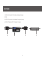
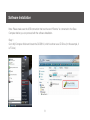
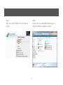
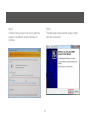
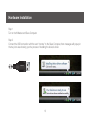
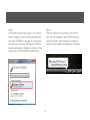
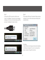
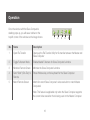
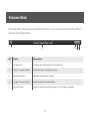
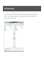
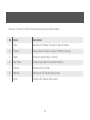
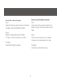
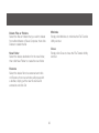
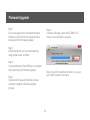
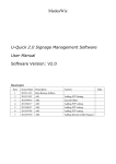
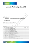
Installation Guide
USB Laptop KVM Switch
GCS661U
1
2
Table of Contents
Table of Contents
3
File Transfer Utility
19
Package Contents
4
Firmware Upgrade
23
System Requirements
5
FCC Statement
25
Overview
6
CE Statement
27
Before You Start
7
SJ/T 11364-2006
28
Software Installation
8
Limited Warranty
29
Hardware Installation
13
Contact
30
Operation
16
USB 2.0 Peripheral Port
17
Fullscreen Mode
18
3
Package Contents
1 x USB Laptop KVM Switch
1 x Carrying Pouch
1 x Installation Guide
1 x Warranty Card
4
System Requirements
Computers
• A USB 2.0 Type A port from the Master Computer*
• A USB 2.0 Type A port from the Slave Computer**
Operating System
• Windows XP
• Windows Vista (32-bit / 64-bit)
• Windows 7
*The term “Master Computer” will be shown throughout the Installation guide. “Master Computer” refers to
the computer that you will be using as the Console – Monitor, keyboard and mouse.
**The term “Slave Computer” will be shown throughout the Installation guide. “Slave Computer” refers to
the computer that is being accessed remotely by the Master Computer.
5
Overview
1. USB 2.0 Connection for the Slave Computer (longer)
2. LEDs
3. USB 2.0 Connection for the Master Computer (shorter)
4. USB 2.0 Peripheral Port for Master Computer
1
2
3
6
4
Before You Start
If you wish the Slave Computer to be ready for access every time after booting up or after GCS661U is
plugged in without the present of a monitor, keyboard and mouse connected to the Slave Computer, the
following procedures are required:
1. Remove all user accounts besides the one that you will be using to access from the Master Computer.
2. Disable login password on the Slave Computer.
3. Install Laptop KVM Remote Software onto the Slave Computer. Please refer to the Software Installation
section for details.
7
Software Installation
Note: Please make sure the USB connection that has the word “Remote” is connected to the Slave
Computer before you can proceed with the software installation.
Step 1
Go to My Computer folder and locate the GCS661U, which is shown as a CD Drive. (In this example, it
is F Drive)
8
Step 3
Double-click on Laptop KVM Remote Setup to
begin the software installation process.
Step 2
Right click on the GCS661U drive and click on
Explore.
9
Step 4
A Window may popup to ask you to grant the
access for installation, simply click Allow to
continue.
Step 5
The initial setup screen will then popup, simply
click next to proceed.
10
Step 7
Select the desire destination that you wish to have
the shortcuts, then simply click Next to continue.
Step 6
Select the desire destination that you wish to have
the software installed, then simply click Next to
continue.
11
Final Step
Once the installation is completed, simply click
Finish to complete the software installation setup.
(If you do not wish to use GCS661U at this
moment, uncheck the Start Laptop KVM Remote
checkbox before you click Finish.)
Step 8
This screen shows the desire destination and Start
Menu Folder name for double-checking. If they are
correct, simply click Install to begin the installation
process.
12
Hardware Installation
Step 1
Turn on both Master and Slave Computer
Step 2
Connect the USB connection with the word “remote” to the Slave Computer, then messages will popup in
the tray icon area showing you the process of installing the device’s driver.
REMOTE
LOCAL
13
Step 3
An AutoPlay window may popup. If you wish the
Slave Computer to auto-start the software every
time when GCS661U is plugged in or every time
after boot-up, make sure the “Always do this for
software and games” checkbox is checked. Then
simply click on “Run IOGEAR GCS661U.exe”
Step 4
Then the software icon will show up in the tray
icon, and the message “Laptop KVM Remote is
running” is shown when the Slave Computer is
ready to be accessed from the Master Computer.
14
Step 6
Then Laptop KVM Local Connection Status window
will popup, and it will be closed automatically after
a few seconds.
Step 5
Connect the USB connection with the word
REMOTE
“local” to the Master
Computer, then messages
will popup in the tray icon area showing you the
process of installing the device’s driver.
LOCAL
Final Step
A new window should popup showing the desktop
of the Slave Computer. You can now access the
Slave computer through this window.
15
Operation
Once the window with the Slave Computer’s
desktop pops up, you will see a toolbar on the
top left corner of the window as the image shown.
1
2
3
4
5
No.
Name
Description
1
Open File Transfer
Opens up the File Transfer Utility for file transfer between the Master and
Slave Computer
2
Toggle Fullscreen Mode
Enable/disable Fullscreen for Slave Computer’s window
3
Minimize Remote Screen
Minimize the Slave Computer’s window
4
Send “Start” (Ctrl+Esc) to
Remote
Press Windows key on the keyboard for the Slave Computer
5
Match Remote Screen
Match/Un-match Slave Computer’s video resolution to match Master
Computer’s
Note: This feature is applicable only when the Slave Computer supports
the current video resolution that is being used on the Master Computer
16
USB 2.0 Peripheral Port
This USB 2.0 port is for the use of the Master Computer only. You can connect any USB device to it and the
device can be used as if it is connected directly to the Master Computer.
Note: If you are connecting a USB harddrive to the USB 2.0 peripheral port, an external power supply for the
harddrive is required.
17
Fullscreen Mode
If Fullscreen Mode is being used, an auto-hide bar will show up if you move the cursor to the top middle of
the screen as the image shown.
1
2
3 4 5
No.
Name
Description
1
Pin Board Pin
Pin/unpin auto-hide bar from the fullscreen
2
Slave Computer’s Name
Shows the Slave Computer’s name
3
Minimize Window
Minimize the fullscreen window
4
Toggle Fullscreen Mode
Disable/enable Fullscreen Mode
5
Close Window
Close the window and disconnect from the Slave Computer
18
File Transfer Utility
After clicking on the Open File Transfer button from the toolbar, a window will popup as the picture is
shown. The left side shows the directories from the Master Computer and the right side shows the
directories from the Slave Computer.
19
There are 7 functions in the File Transfer Utility and they are listed as below:
No.
Name
Description
1
Send
Send files from Master Computer to Slave Computer
2
Receive
Receive files from Slave Computer to Master Computer
3
Delete
Delete the selected file(s) or folder(s)
4
New Folder
Create a new folder in the selected directory
5
Rename
Rename a file or a folder
6
Minimize
Minimize the File Transfer Utility window
7
Close
Close the File Transfer Utility window
20
Receive a file from Slave Computer
Step 1
Select the file that you wish to transfer to the
Master Computer in the Remote Machine root
table
Send a file to Slave Computer
Step 1
Select the file that you wish to transfer to the Slave
Computer in the Local Machine root table
Step 2
Select the desire destination on the Slave
Computer in the Remote Machine root table
Step 2
Select the desire destination on the Master
Computer in the Local Machine root table
Final Step
Click Send to begin the process.
Final Step
Click Receive to begin the process.
21
Minimize
Simply click Minimize to minimize the File Transfer
Utility window
Delete Files or Folders
Select the files or folders that you wish to delete
from either Master or Slave Computer, then click
Delete to delete the file
Close
Simply click Close to close the File Transfer Utility
window
New Folder
Select the desire destination for the new folder,
then click New Folder to create the new folder
Rename
Select the desire file to be renamed and click
on Rename, then new window will popup with
a textbar, simply put the new file name and
extension and click Ok
22
Firmware Upgrade
Step 1
Go to www.iogear.com to download the latest
firmware for the unit from the computer that is
being used for the firmware upgrade.
Step 5
A window will popup, select the GCS661U CD
drive no. then click start to proceed.
Step 2
Extract the file that you have downloaded by
using software such as Winrar.
Step 3
Connect either end of the USB port to computer
that is performing the firmware upgrade.
Note: if you don’t remember the drive no., you can
go to “My Computer” and check.
Step 4
Double-click the execution file that you have
extracted to begin the firmware upgrade
process.
23
Final Step
Once the firmware upgrade has completed, a
window will popup and say Upgrade Success,
simply click OK to complete the firmware upgrade
process.
Step 6
Then the new firmware will begin to load into the
GCS661U.
24
FCC Statement
15.21
You are cautioned that changes or modifications not expressly approved by the part responsible for
compliance could void the user’s authority to operate the equipment.
15.105(b)
his equipment has been tested and found to comply with the limits for a Class B digital device, pursuant
to part 15 of the FCC rules. These limits are designed to provide reasonable protection against harmful
interference in a residential installation. This equipment generates, uses and can radiate radio frequency
energy and, if not installed and used in accordance with the instructions, may cause harmful interference
to radio communications. However, there is no guarantee that interference will not occur in a particular
installation. If this equipment does cause harmful interference to radio or television reception, which can
be determined by turning the equipment off and on, the user is encouraged to try to correct the
interference by one or more of the following measures:
- Reorient or relocate the receiving antenna.
- Increase the separation between the equipment and receiver.
- Connect the equipment into an outlet on a circuit different from that to which the receiver is connected.
- Consult the dealer or an experienced radio/TV technician for help.
25
THIS DEVICE COMPLIES WITH PART 15 OF THE FCC RULES. OPERATION IS SUBJECT TO THE
FOLLOWING TWO CONDITIONS:
1. this device may not cause interference and
2. this device must accept any interference, including interference that may cause undesired operation of the device.
FCC RF Radiation Exposure Statement:
This equipment complies with FCC radiation exposure limits set forth for an uncontrolled environment.
End users must follow the specific operating instructions for satisfying RF exposure compliance. This
transmitter must not be co-located or operating in conjunction with any other antenna or transmitter.
26
CE Statement
This device has been tested and found to comply with the requirements set up in the council directive on
the approximation of the law of member states relating to EMC Directive 89/336/EEC, Low Voltage
Directive 73/23/EEC and R&TTE Directive 99/5/EC.
The product has been approved for LVD and covered the following countries:
Belgium, Denmark, France, Germany, Italy, Portugal, U.K., Spain, Sweden
27
SJ/T 11364-2006
The following contains information that relates to China.
有毒有害物质或元素
部件名称
镉(Cd)
六价 (Cr(VI))
多溴联苯
(PBB)
多溴二苯醚
(PBDE)
铅 (Pb)
汞 (Hg)
电器部件
●
○
○
○
○
○
机构部件
○
○
○
○
○
○
○:表示该有毒有害物质在该部件所有均质材料中的含量均在SJ/T 11363-2006规定的限量要求之下。
●:表示符合欧盟的豁免条款,但该有毒有害物质至少在该部件的某一均质材料中的含量超出
SJ/T 11363-2006的限量要求。
×: 表示该有毒有害物质至少在该部件的某一均质材料中的含量超出SJ/T 11363-2006的限量要求。
28
Limited Warranty
IN NO EVENT SHALL THE DIRECT VENDOR’S LIABILITY FOR DIRECT, INDIRECT, SPECIAL,
INCIDENTAL OR CONSEQUENTIAL DAMAGES RESULTING FROM THE USE OF THE PRODUCT, DISK,
OR ITS DOCUMENTATION EXCEED THE PRICE PAID FOR THE PRODUCT.
The direct vendor makes no warranty or representation, expressed, implied, or statutory with respect to
the contents or use of this documentation, and especially disclaims its quality, performance,
merchantability, or fitness for any particular purpose.The direct vendor also reserves the right to revise or
update the device or documentation without obligation to notify any individual or entity of such revisions,
or updates. For further inquiries please contact IOGEAR.
29
Contact
IOGEAR, INC.
19641 DaVinci
Foothill Ranch, CA 92610
P 949.453.8782
F 949.453.8785
Visit us at: www.iogear.com
© 2009 IOGEAR®. All Rights reserved. Part No. M1069
IOGEAR, the IOGEAR logo, are trademarks or registered trademarks of IOGEAR, Inc. Microsoft and Windows are
registered trademarks of Microsoft Corporation. All other brand and product names are trademarks or registered
trademarks of their respective holders. IOGEAR makes no warranty of any kind with regards to the information presented
in this document. All information furnished here is for informational purposes only and is subject to change without
notice. IOGEAR, Inc. assumes no responsibility for any inaccuracies or errors that may appear in this document.
30
31
About Us
FUN
IOGEAR offers connectivity solutions that are innovative, fun, and stylish,
helping people enjoy daily life using our high technology products.
GREEN
IOGEAR is an environmentally conscious company that emphasizes the
importance of conserving natural resources. The use of our technology
solutions helps reduce electronic waste.
HEALTH
IOGEAR supports healthy and fit lifestyles. By integrating products with the
latest scientific developments, IOGEAR’s solutions enhance the life of endusers.
Part No. M1069
© 2009 IOGEAR®