1
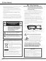
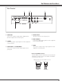
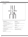
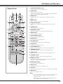
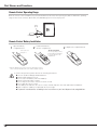
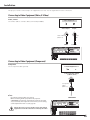
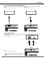
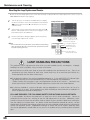
Multimedia Projector
MODEL PLV-Z3000
Owner’s Manual
To the Owner
Safety Precaution
Before operating this projector, read this manual thoroughly
and operate the projector properly.
This projector provides many convenient features and
functions. Operating the projector properly enables you to
manage those features and maintain it in good condition for
many years to come.
Improper operation may result in not only shortening the
product life, but also malfunctions, fire hazard, or other
accidents.
If your projector seems to operate improperly, read this
manual again, check operations and cable connections, and
try the solutions in the “Troubleshooting” section in the back
of this manual. If the problem still persists, contact the dealer
where you purchased the projector or the service center.
CAUTION
RISK OF ELECTRIC SHOCK
DO NOT OPEN
CAUTION: TO REDUCE THE RISK OF ELECTRIC
SHOCK, DO NOT REMOVE COVER (OR
BACK). NO USER-SERVICEABLE PARTS
INSIDE EXCEPT LAMP REPLACEMENT.
REFER SERVICING TO QUALIFIED
SERVICE PERSONNEL.
THIS SYMBOL INDICATES THAT DANGEROUS
VOLTAGE CONSTITUTING A RISK OF ELECTRIC
SHOCK IS PRESENT WITHIN THIS UNIT.
THIS SYMBOL INDICATES THAT THERE ARE
IMPORTANT OPERATING AND MAINTENANCE
INSTRUCTIONS IN THE OWNER’S MANUAL WITH
THIS UNIT.
NOTE:
This symbol and recycle system are applied to EU
countries only and not to the countries in the other area
of the world.
Your SANYO product is designed and
manufactured with high quality materials
and components which can be recycled
and reused.
This symbol means that electrical and
electronic equipment, at their end-of-life,
should be disposed of separately from
your household waste.
Please dispose of this equipment at your
local community waste collection/recycling centre.
In the European Union there are separate collection
systems for used electrical and electronic products.
Please help us to conserve the environment we live in!
READ AND KEEP THIS OWNER’S MANUAL FOR LATER
USE.
WARNING: THIS APPARATUS MUST BE EARTHED.
TO REDUCE THE RISK OF FIRE OR ELECTRIC
SHOCK, DO NOT EXPOSE THIS APPLIANCE TO
RAIN OR MOISTURE.
– This projector produces intense light from the projection
lens. Avoid staring directly into the lens as much as possible,
otherwise eye damage could result. Be especially careful
that children do not stare directly into the beam.
– Install the projector in a proper position. Otherwise it may
result in fire hazard.
– Allowing the proper amount of space on the top, sides,
and rear of the projector cabinet is critical for proper air
circulation and cooling of the unit. The dimensions shown
here indicate the minimum space required. If the projector
is to be built into a compartment or similarly enclosed, these
minimum distances must be maintained.
– Do not cover the ventilation slot on the projector. Heat buildup can reduce the service life of your projector, and can also
be dangerous.
SIDE and TOP
REAR
1.5' (50 cm)
3' (1 m)
1.5' (50 cm)
1.5' (50 cm)
– If the projector is unused for an extended time, unplug the
projector from the power outlet.
CAUTION ON HANGING FROM THE CEILING
When hanging the projector from the
ceiling, clean the air intake vents, air filters,
and the top of the projector periodically
with a vacuum cleaner. If you leave the
projector unclean for a long time, the
cooling fans can be clogged with dust, and
it may cause a breakdown or a disaster.
Do not set the projector in greasy, wet,
or smoky conditions such as IN a kitchen
to prevent A Breakdown or disaster. If the
projector comes in contact with oil or
chemicals, it may become deteriorated.
CAUTION
Not for use in a computer room as defined in the
Standard for the Protection of Electronic Computer/Data
Processing Equipment, ANSI/NFPA 75.
Ne peut être utilisé dans une salle d’ordinateurs telle
que définie dans la norme ANSI/NFPA 75 Standard for
Protection of Electronic Computer/Data Processing
Equipment.
Safety Instructions
All the safety and operating instructions should be read before
the product is operated.
Read all of the instructions given here and retain them for
later use. Unplug this projector from AC power supply before
cleaning. Do not use liquid or aerosol cleaners. Use a damp
cloth for cleaning.
This projector should be operated only from the type of power
source indicated on the marking label. If you are not sure of
the type of power supplied, consult your authorized dealer or
local power company.
Follow all warnings and instructions marked on the projector.
Do not overload wall outlets and extension cords as this can
result in fire or electric shock. Do not allow anything to rest on
the power cord. Do not locate this projector where the cord
may be damaged by persons walking on it.
For added protection to the projector during lightning storm, or
when it is left unattended and unused for long periods of time,
unplug it from the wall outlet. This will prevent damage due to
lightning and power line surges.
Do not attempt to service this projector yourself as opening
or removing covers may expose you to dangerous voltage
or other hazards. Refer all servicing to qualified service
personnel.
Do not expose this unit to rain or use near water... for
example, in a wet basement, near a swimming pool, etc...
Do not use attachments not recommended by the
manufacturer as they may cause hazards.
Do not place this projector on an unstable cart, stand, or
table. The projector may fall, causing serious injury to a child
or adult, and serious damage to the projector. Use only with
a cart or stand recommended by the manufacturer, or sold
with the projector. Wall or shelf mounting should follow the
manufacturer’s instructions, and should use a mounting kit
approved by the manufacturers.
An appliance and cart combination
should be moved with care. Quick stops,
excessive force, and uneven surfaces
may cause the appliance and cart
combination to overturn.
Slots and openings in the back and bottom of the cabinet are
provided for ventilation, to ensure reliable operation of the
equipment and to protect it from overheating.
Unplug this projector from wall outlet and refer servicing to
qualified service personnel under the following conditions:
a. When the power cord or plug is damaged or frayed.
b. If liquid has been spilled into the projector.
c. If the projector has been exposed to rain or water.
d. If the projector does not operate normally by following
the operating instructions. Adjust only those controls that
are covered by the operating instructions as improper
adjustment of other controls may result in damage and will
often require extensive work by a qualified technician to
restore the projector to normal operation.
e. If the projector has been dropped or the cabinet has been
damaged.
f. When the projector exhibits a distinct change in
performance, this indicates a need for service.
When replacement parts are required, be sure the service
technician has used replacement parts specified by the
manufacturer that have the same characteristics as the original
part. Unauthorized substitutions may result in fire, electric
shock, or injury to persons.
Upon completion of any service or repairs to this projector,
ask the service technician to perform routine safety checks to
determine that the projector is in safe operating condition.
The openings should never be covered with cloth or other
materials, and the bottom opening should not be blocked
by placing the projector on a bed, sofa, rug, or other similar
surface. This projector should never be placed near or over a
radiator or heat register.
This projector should not be placed in a built-in installation
such as a bookcase unless proper ventilation is provided.
Never push objects of any kind into this projector through
cabinet slots as they may touch dangerous voltage points
or short out parts that could result in a fire or electric shock.
Never spill liquid of any kind on the projector.
Do not install the projector near the ventilation duct of airconditioning equipment.
Compliance
Federal Communications Commission Notice
This equipment has been tested and found to comply with the limits for a Class B digital device, pursuant to Part 15 of the FCC Rules.
These limits are designed to provide reasonable protection against harmful interference in a residential installation. This equipment
generates, uses, and can radiate radio frequency energy. If it is not installed and used in accordance with the instructions, it may cause
harmful interference to radio communications. However, there is no guarantee that interference will not occur in a particular installation. If
this equipment does cause harmful interference to radio or television reception, which can be determined by turning the equipment off and
on, the user is encouraged to try to correct the interference by one or more of the following measures:
– Reorient or relocate the receiving antenna.
– Increase the separation between the equipment and receiver.
– Connect the equipment into an outlet on a circuit different from that to which the receiver is connected.
– Consult the dealer or an experienced radio/TV technician for help.
Use of shielded cable is required to comply with class B limits in Subpart B of Part 15 of FCC Rules.
Do not make any changes or modifications to the equipment unless otherwise specified in the instructions. If such changes or modifications
should be made, you could be required to stop operation of the equipment.
Model Number(s)
Trade Name
Responsible party
Address
Telephone No.
: PLV-Z3000
: Sanyo
: SANYO FISHER COMPANY
: 21605 Plummer Street, Chatsworth, California 91311
: (818)998-7322
AC Power Cord Requirement
The AC Power Cord supplied with this projector meets the requirement for use in the country you purchased it.
AC Power Cord for the United States and Canada:
AC Power Cord used in the United States and Canada is listed by the Underwriters Laboratories (UL) and
certified by the Canadian Standard Association (CSA).
AC Power Cord has a grounding-type AC line plug. This is a safety feature to be sure that the plug will fit into the
power outlet. Do not try to defeat this safety feature. Should you be unable to insert the plug into the outlet,
contact your electrician.
GROUND
AC Power Cord for the United Kingdom:
This cord is already fitted with a moulded plug incorporating a fuse, the value of which is indicated on the pin face of the plug. Should the
fuse need to be replaced, an ASTA approved BS 1362 fuse must be used of the same rating, marked thus
. If the fuse cover is
detachable, never use the plug with the cover omitted. If a replacement fuse cover is required, ensure it is of the same colour as that
visible on the pin face of the plug (i.e. red or orange). Fuse covers are available from the Parts Department indicated in your User
Instructions.
If the plug supplied is not suitable for your socket outlet, it should be cut off and destroyed.
The end of the flexible cord should be suitably prepared and the correct plug fitted.
ASA
WARNING: A PLUG WITH BARED FLEXIBLE CORD IS HAZARDOUS IF ENGAGED IN A LIVE SOCKET
OUTLET.
The Wires in this mains lead are coloured in accordance with the following code:
Green-and-yellow ············ Earth
Blue ································· Neutral
Brown ······························ Live
As the colours of the wires in the mains lead of this apparatus may not correspond with the coloured markings identifying the terminals in
your plug proceed as follows:
The wire which is coloured green-and-yellow must be connected to the terminal in the plug which is marked by the letter E or by the safety
earth symbol
or coloured green or green-and-yellow.
The wire which is coloured blue must be connected to the terminal which is marked with the letter N or coloured black.
The wire which is coloured brown must be connected to the terminal which is marked with the letter L or coloured red.
WARNING: THIS APPARATUS MUST BE EARTHED.
THE SOCKET-OUTLET SHOULD BE INSTALLED NEAR THE EQUIPMENT AND EASILY ACCESSIBLE.
6
Safety Instructions
Air Circulation
Installing the Projector in Proper Position
Openings in the cabinet are provided for ventilation. To
ensure reliable operation of the product and to protect it from
overheating, these openings must not be blocked or covered.
Install the projector properly. Improper installation may reduce
the lamp life and cause fire hazard.
20˚
CAUTION
Do not tilt the projector more than 20
degrees from side to side.
20˚
Hot air is exhausted from the exhaust vent. When using or
installing the projector, the following precautions should be
taken.
– Do not put any flammable objects or spray can near the
projector. Hot air is exhausted from the ventilation holes.
– Keep the exhaust vent at least 3’ (1 m) away from any
objects.
– Do not touch a peripheral part of the exhaust vent,
especially screws and metallic part. This area will become
hot while the projector is being used.
– Do not put anything on the projector. Objects put on the
cabinet will not only get damaged but also cause fire
hazard by heat.
Cooling fans are provided to cool down the projector.
The fan’s running speed is changed according to the
temperature inside the projector.
Do not point the projector up to
project an image.
NO UPWARD
Do not point the projector down to
project an image.
NO DOWNWARD
Do not put the projector on either side
to project an image.
NO SIDEWARD
Moving the Projector
Air Intake Vent
Exhaust Vent
(Hot air exhaust)
When moving the projector, make sure that the automatic
slide shutter is closed, retract the adjustable feet, and lock the
lens with the Lens Shift Lock to prevent damage to the lens
and cabinet.
When the projector is unused for an extended period, put it
into a suitable case.
Care must be taken when handling the projector; do not drop,
bump, subject it to strong forces, or put other things on the
cabinet.
CAUTION IN CARRYING OR
TRANSPORTING THE PROJECTOR
CAUTION ON CEILING MOUNTING
For ceiling mounting, you need the ceiling mount kit
designed for this projector. When not mounted properly,
the projector may fall, causing hazards or injury. For
details, consult your dealer. The warranty on this projector
does not cover any damage caused by use of any nonrecommended ceiling mount kit or installation of the
ceiling mount kit in an improper location.
7
– Do not drop or bump the projector, otherwise damages or
malfunctions may result.
– When carrying the projector, use a suitable carrying case.
– Do not transport the projector by courier or any other
transport service in an unsuitable transport case. This
may cause damage to the projector. For information
about transporting the projector by courier or any other
transport service, consult your dealer.
– Do not put the projector in a case before it is cooled
enough.
Installation
Connecting the AC Power Cord
This projector uses nominal input voltages of 100 – 120 V or 200
– 240 V AC and it automatically selects a correct input voltage. It is
designed to work with the single-phase power systems having a
grounded neutral conductor. To reduce the risk of electrical shock,
do not plug into any other type of power system.
If you are not sure of the type of power being supplied, consult
your authorized dealer or service station.
Connect the projector with all peripheral equipment before turning
it on.
CAUTION
The AC outlet must be near this equipment and must be easily
accessible.
Connect the AC power cord (supplied) to the
projector.
✔Note:
For safety, unplug the AC power cord when the projector is not
in use.
When the projector is connected to an outlet with the AC
power cord and the Main On/Off switch is on, it is in stand-by
mode and consumes a little electric power. Turn the Main On/
Off switch off when the projector is not in use.
NOTE ON THE POWER CORD
AC power cord must meet the requirements of the country where you use the projector.
Confirm the AC plug type with the chart below and proper AC power cord must be used.
If the supplied AC power cord does not match your AC outlet, contact your sales dealer.
Projector side
AC Outlet side
For the U.S.A. and Canada
For Continental Europe
For the U.K.
Ground
To POWER CORD
CONNECTOR on your
projector.
To the AC Outlet.
(120 V AC)
To the AC Outlet.
(200–240 V AC)
To the AC Outlet.
(200–240 V AC)
8
Part Names and Functions
Rear Terminal
q
w e
r
S-VIDEO
COMPONENT 1
HDMI 1 HDMI 2
COMPUTER
SERVICEPORT
COMPONENT 2
VIDEO
t
y
q COMPUTER
Connect the computer output signal, or RGB Scart 21pin video output to this connector (p.17).
w S-VIDEO
Connect the S-Video output signal from video equipment
to this jack (p.16).
e COMPONENT 1 or COMPONENT 2
Connect the component video output signal to these
jacks (p.16).
Y Pb/Cb Pr/Cr
r SERVICE PORT
This jack is used to service the projector.
t HDMI 1/HDMI 2*
Connect the HDMI output signal from video equipment
to these terminals (p.16).
y VIDEO
Connect the composite video output signal from video
equipment to this jack (p.16).
* Note on the HDMI connector:
Use the HDMI connector less than the size shown below.
Otherwise you cannot connect use HDMI 1 and HDMI 2
terminals at the same time.
Maximum dimensions of the HDMI connectors
0.94" (24 mm)
0.59" (15 mm)
WIDTH
THICKNESS
9
Part Names and Functions
Top Control
e
w
q
o
r
t
y
u
q POWER indicator
– Lights red while the projector is in stand-by mode.
– Lights green during operations.
– Blinks red during the cooling-off period.
– Blinks green in the Power management mode (p.41).
– Blinks orange when the automatic slide shutter is
closed during operations (p.53).
w WARNING indicator
– Lights red light when the projector detects an abnormal
condition.
– Blinks red when the internal temperature of the
projector exceeds the operating range (pp.44, 53).
e LAMP REPLACE indicator
Lights yellow light when the projection lamp reaches its
end of life (pp.49, 53).
r MENU button
Open or close the On-Screen Menu (p.20).
10
i
t INPUT button
Select an input source (p.24).
y POINT ed7 8 buttons
Select an item or adjust the setting values in the OnScreen Menu.
u OK button
Execute the item selected or use it to access the
submenu items (p.20).
i INFO. button
Display the input source information (p.43).
o POWER ON/STAND-BY button
Turn the projector on or off (pp.18, 19).
Part Names and Functions
q POWER ON/STAND-BY button
Turn the projector on or off (pp.18, 19).
Remote Control
e
w
w RESET button
Reset to the previous figure.
This function is limited to when selecting the Image Adjustment
(pp.28 – 33) and Picture Adjustment (p.34).
q
e LIGHT button
Light up the remote control buttons for about 10 seconds
(p.22).
r MENU button
Open or close the On-Screen Menu (p.20).
r
@1
t POINT ed7 8 buttons
Select an item or adjust the setting values in the On-Screen
Menu.
@0
y SCREEN button
Select a screen size (pp.22, 35).
u BRIGHTNESS button
Adjust the brightness of a projected image (pp.23, 28).
t
y
!9
!8
o LAMP CONTROL button
Select a lamp mode (pp.23, 29).
!7
!0 FREEZE button
Freeze the projected image (p.23).
u
!6
i
i INPUT buttons
Select an input source (p.24).
!5
!1 NO SHOW button
Temporarily turn off the projected image (p.23).
!4
!2 LOGO button
Display the captured logo (p.23).
!3
!3 COLOR TEMP. button
Adjust the color temperature of a projected image (p.28).
!2
!1
!4 SHARPNESS button
Adjust the sharpness of a projected image (pp.23, 29).
!0
!5 COLOR button
Adjust the color intensity of a projected image (pp.23, 28).
!6 CONTRAST button
Adjust the contrast of a projected image (pp.23, 28).
!7 IMAGE ADJ. button
Display the Image adj. Menu items one at a time and directly
adjust the selected items (pp.23, 28).
!8 IMAGE MODE buttons
Select an image mode (pp.23, 27).
o
!9 INFO. button
Display the input source information (p.43).
@0 OK button
Execute the selected item or access the sub-menu items (p.20).
@1 BACK button
Return to the previous menu.
✔Note:
To ensure safe operation, observe the following precautions:
– Do not bend, drop, or expose the remote control to
moisture or heat.
– For cleaning, use a soft dry cloth. Do not apply benzene,
thinner, splay, or any other chemicals.
11
Part Names and Functions
Remote Control Operating Range
Point the remote control toward the projector (Infrared Remote Receiver) when pressing any buttons. Maximum operating
range for the remote control is about 16.4’ (5 m) and 60 degrees in front of the projector.
16.4’
(5 m)
30°
Remote control
30°
Remote Control Battery Installation
1
Open the battery
compartment lid.
2
Install new batteries
into the compartment.
Pull up the lid
and open it.
3
Replace the compartment lid.
Two AA size batteries
For correct polarity (+ and –),
be sure battery terminals are
in contact with pins in the
compartment.
* When the batteries of the remote control are replaced, the remote
control code automatically returns to the initial code (Code 1) (p.41).
To ensure safe operation, please observe the following precautions:
● Use two (2) AA or LR6 type alkaline batteries.
● Always replace batteries in sets.
● Do not use a new battery with a used battery.
● Avoid contact with water or liquid.
● Do not expose the remote control to moisture or heat.
● Do not drop the remote control.
● If the battery has leaked on the remote control, carefully wipe the case clean and install new batteries.
● Risk of explosion if battery is replaced by an incorrect type.
● Dispose of used batteries according to the instructions or your local disposal rule and guidelines.
12
Installation
This projector can be connected up to six equipment at one time. See the figures below for the connections.
Connecting to Video Equipment (Video, S-Video)
Video, S-video
Use a video cable or a S-video cable (commercially available).
Video Equipment
Composite
Video Output
Video Cable
(RCA x 1)
S-VIDEO
Output
S-video
Cable
VIDEO
S-VIDEO
Connecting to Video Equipment (Component)
Component
Use a component cable (optional).
Video Equipment
Component Video Output
(Y, Pb/Cb, Pr/Cr)
Component
Cable
(RCA x 3)
✔Note:
• To order the optional cables, see page 58.
• When connecting HDTV equipment to the projector’s
COMPONENT 1/2 terminals, horizontal line noise may be noted
only occasionally. Then adjust the value of Fine sync. The setting
can be adjusted from 0 to +31 (see page 34).
COMPONENT
Unplug the power cords of both the projector and external
equipment from the AC outlet before connecting the cables.
15
Installation
Connecting to Video Equipment (HDMI, RGB Scart)
HDMI
Use a HDMI cable (optional) for HDMI output.
RGB Scart
Use a Scart-VGA cable (optional).
Video Equipment
Video Equipment
HDMI Video
Output
HDMI
Cable
RGB Scart
21-pin Output
Scart-VGA
Cable
COMPUTER
HDMI
Connecting to a Computer
Computer (Analog)
Use a VGA cable (commercially available) or a DVI-VGA cable
(commercially available).
Computer
Monitor Out
DVI-VGA
Cable
VGA
Cable
COMPUTER
✔Note:
• To order the optional cables, see page 58.
Unplug the power cords of both the projector and external
equipment from the AC outlet before connecting the cables.
16
Maintenance and Cleaning
Lamp Replacement
When the projection lamp of this projector reaches its end of life,
the LAMP REPLACE indicator emits yellow light. If this indicator
lights yellow, replace the lamp with a new one promptly.
The time when the LAMP REPLACE indicator should light is
depending on the lamp mode.
Top Control
This indicator lights yellow
when the projection lamp
reaches its end of life.
CAUTION
CAUTION
Allow a projector to cool, for at least 45 minutes before
you open the Lamp cover. The inside of the projector
can become very hot.
For continued safety, replace with a lamp of the same
type. Do not drop a lamp or touch a glass bulb! The
glass can shatter and may cause injury.
Screw
Follow these steps to replace the lamp.
1
Turn off the projector and unplug the AC power cord. Let the
projector cool for at least 45 minutes.
2
Loosen the screw that secures the lamp cover, and then
open the lamp cover.
3
Loosen the two (2) screws that secure the lamp. Pull out the
lamp by using the built in handle.
4
Replace the lamp with a new one and secure it with the two
(2) screws. Make sure that the lamp is set properly. Put the
lamp cover back and secure it with the screw.
5
Connect the AC power cord to the projector and turn on the
projector.
6
(p.50).
Reset the Lamp replacement counter
Lamp Cover
Handle
Lamp
Screws
ORDER REPLACEMENT LAMP
Replacement lamp can be ordered through your dealer. When ordering a projection lamp, give the following information
to the dealer.
●
Model No. of your projector
● Replacement Lamp Type No.
:
:
PLV-Z3000
POA-LMP114
(Service Parts No. 610 336 5404)
45
Maintenance and Cleaning
Resetting the Lamp Replacement Counter
Be sure to reset the lamp replacement counter after the lamp is replaced. When the lamp replacement counter is reset, the
LAMP REPLACE indicator stops lighting.
1
Turn the projector on and press the MENU button to display
the On-Screen Menu. Select the Setting Menu with the Point
ed buttons. Press the Point 8 or OK buttons to access the
submenu items.
2
Select Lamp counter reset and then press the OK or Point 8
buttons. “Lamp replacement counter reset?” appears. Select
[Yes] and then press the OK button.
3
Another confirmation dialog box appears, and select [Yes] to
reset the Lamp replacement counter.
✔Note:
• Do not reset the Lamp replacement counter without implementing
lamp replacement. Be sure to reset the Lamp replacement counter
only after replacing the lamp.
Lamp counter reset
Select Lamp counter reset
and press the OK or Point 8
buttons. “Lamp replacement
counter reset?” appears.
Select [Yes] and press
the OK button, then
another confirmation
box appears.
Select [Yes] again to
reset the lamp counter.
LAMP HANDLING PRECAUTIONS
This projector uses a high-pressure lamp which must be handled carefully and properly. Improper
handling may result in accidents, injury, or create a fire hazard.
● Lamp lifetime may differ from lamp to lamp and according to the environment of use. There is no
guarantee of the same lifetime for each lamp. Some lamps may fail or terminate their lifetime in a
shorter period of time than other similar lamps.
● If the projector indicates that the lamp should be replaced, i.e., if the LAMP REPLACE indicator lights
up, replace the lamp with a new one IMMEDIATELY after the projector has cooled down.
( Follow carefully the instructions in the Lamp Replacement section of this manual. ) Continuous use
of the lamp with the LAMP REPLACE indicator lighted may increase the risk of lamp explosion.
● A Lamp may explode as a result of vibration, shock or degradation as a result of hours of use as its
lifetime draws to an end. Risk of explosion may differ according to the environment or conditions in
which the projector and lamp are being used.
IF A LAMP EXPLODES, THE FOLLOWING SAFETY PRECAUTIONS SHOULD BE TAKEN.
If a lamp explodes, disconnect the projector’s AC plug from the AC outlet immediately. Contact an
authorized service station for a checkup of the unit and replacement of the lamp. Additionally, check
carefully to ensure that there are no broken shards or pieces of glass around the projector or coming out
from the cooling air circulation holes. Any broken shards found should be cleaned up carefully. No one
should check the inside of the projector except those who are authorized trained technicians and who are
familiar with projector service. Inappropriate attempts to service the unit by anyone, especially those
who are not appropriately trained to do so, may result in an accident or injury caused by pieces of broken
glass.
46
Appendix
Technical Specifications
Projector Type
Dimensions (W x H x D)
Net Weight
LCD Panel System
Panel Resolution
Number of Pixels
Color System
High Definition TV Signal
Scanning Frequency
Projection Image size (Diagonal)
Projection Lens
Throw Distance
Projection Lamp
Video Input jacks
Computer Input Terminal
HDMI Input Terminals
Service Port Connector
Feet Adjustment
Voltage and
Power Consumption
Operating Temperature
Storage Temperature
Multimedia Projector
15.75” x 5.75” x 13.62” (400 mm x 146 mm x 346 mm) (not including raised portions)
16.1 lbs (7.3 kg)
0.74” wide TFT Active Matrix type, 3 panels
1920 x 1080 dots
6,220,800 (1920 x 1080 x 3 panels)
PAL, SECAM, NTSC, NTSC4.43, PAL-M, and PAL-N
480i, 480p, 575i, 575p, 720p, 1080i, and 1080p
H-sync. 15 kHz – 80 kHz, V-sync. 50 Hz – 100 Hz
Adjustable from 40” to 300”
F 2.0 – 3.05 lens with f 22.6 – 45.3 mm with manual zoom and focus
3.9’ – 60.4’ (1.2 m – 18.4 m)
165 W
RCA Type x 1 (Video), RCA Type x 3 (Y, Pb/Cb, Pr/Cr) x 2 and Mini DIN 4 pin x 1 (S-video)
mini D-sub 15 pin x 1
HDMI terminal 19 pin x 2
Mini DIN 8 pin x 1
0˚ to 6.5˚
AC 100 – 120 V (2.9 A Max. Ampere), 50/60 Hz (The U.S.A. and Canada)
AC 200 – 240 V (1.6 A Max. Ampere), 50/60 Hz (Continental Europe and The U.K.)
41˚F – 95˚F (5˚C – 35˚C)
14˚F – 140˚F (-10˚C – 60˚C)
Remote Control
Power Source
Operating Range
Dimensions
Net Weight
:
:
:
:
AA or LR6 1.5 V ALKALINE Type x 2
16.4’ (5 m)/±30˚
2.13” x 1.04” x 6.81” (54 mm x 26.3 mm x 173mm)
3.4 oz (95.5 g) (not including batteries)
Accessories
Owner’s Manual (CD-ROM)
Quick Reference Guide
AC Power Cord
Remote Control and Batteries
Air Blower
● The specifications are subject to change without notice.
● LCD panels are manufactured to the highest possible standards. Even though 99.99% of the pixels are effective, a tiny
fraction of the pixels (0.01% or less) may be ineffective by the characteristics of the LCD panels.
This symbol on the nameplate means the product is Listed by Underwriters Laboratories
Inc. It is designed and manufactured to meet rigid U.L. safety standards against risk of
fire, casualty and electrical hazards.
The CE Mark is a Directive conformity mark of the European Community (EC).
Pixelworks ICs used.
53