1
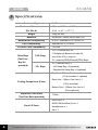
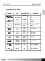
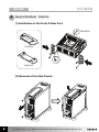
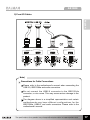
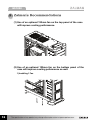
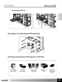
GS1000
English version
◈ Please read this manual thoroughly before installation.
◈ Please visit the GS1000 web page at Zalman’s website to view the GS1000
installation video.
E-mail: [email protected]
www.zalman.com
GS1000
▣ Contents
1. Cautionary Notes
3
2. Specifications
4
3. Components
5
4. Installation Guide
8
5. Zalman’s Recommendations
2
The specifications of any product may change without prior notice to improve performance
18
GS1000
1 Cautionary Notes
English
(1) Check the condition of the product and its components before installation. If
there is a problem with the product and/or its components, please contact the
retailer for replacement.
(2) Refrain from inserting objects into the system while it is powered ON to avoid
harm to the user and/or product.
(3) Check the manual when connecting cables to prevent short circuiting and
risk of fire.
(4) Do not block any of the air vents.
(5) Keep unit away from heat sources such as direct sunlight, as well as water, oil,
and humidity. Place the unit on a level and stable area that is well-ventilated.
(6) Do not clean any surface with chemical cleaners or solvents.
(chemicals including but not limited to: industrial brightener, wax, benzene,
alcohol, paint thinner, mosquito repellent, aromatics, lubricant, detergent etc.)
(7) If this unit needs to be transported long distances, please ensure that all Hot
Swap HDD’s are securely fastened before transport. Also, please place the
GS1000 in its original packaging for transport.
◈ Disclaimer
Zalman Tech Co., Ltd. is not responsible for any damages due to external
causes, including but not limited to improper use, problems with electrical
power, accident, neglect, alteration, repair, improper installation, or
improper testing.
The specifications of any product may change without prior notice to improve performance
3
GS1000
2 Specifications
Enclosure Type
Enclosure Dimensions
(D x W x H)
Weight
Full Tower
585 mm X 220 mm X 520 mm
x 8.7
(18.9
x 17.7 )
12kg (26.4lb)
Materials
Aluminum/ Plastic (ABS)/ steel (GI)
Motherboard Compatibility
E-ATX / Standard ATX / microATX
PSU Compatibility
PCI/AGP Card Compatibility
Standard ATX / ATX12V
Full Size
External Bay x 4
5.25
Drive Bays
5.25 Bays
(Tool Free
use of two 5.25
bays as
3.5 Internal(HDD)/External(FDD) Bays
Bay Kit
provided)
*2 Adaptors & Bezels included for
3.5
3.5 Bays
Internal Bay x 6
- Hot Swap Bay x 3(standard)
- Regular/Hot Swap Bay x 3(optional)
Top Vent : 120mm Fan Vent x 2
(1 Fan included, 1 optional)
Cooling Components (Fans)
Rear Vent : 120mm Fan Vent x 1
(1 Fan included)
Bottom Vent : 120mm Fan Vent x 2
(Fans optional)
Expansion Card Slots
(Tool Free Bolts provided)
7 Slots
USB Port x 2
Front I/O Ports
IEEE1394(FireWire) Port x 1
Headphones x 1
Mic x 1
4
The specifications of any product may change without prior notice to improve performance
GS1000
3 Components
English
(1) GS1000
POWER
USB 2.0
Headphones
Mic
Front View
Back View
IEEE 1394
Top View
Icon Description
Tools required for assembly
Side View
The specifications of any product may change without prior notice to improve performance
5
GS1000
(2) GS1000 Diagram and Parts Table
6
Item
Part Name
Qty
Item
Part Name
Qty
1
HDD Cover
2
7
Aluminum Door
2
2
HDD Tray
6
8
PSU Bracket
1
3
2 In 1 Bracket
2
9
PSU Fan Bracket
1
4
5.25" Bay Cover
2
10
Rear Foot
1
5
Chassis
1
11
Front Foot
1
6
Top Cover
1
The specifications of any product may change without prior notice to improve performance
GS1000
(3) Included GS1000 Parts
Part
Specification Qty
Description
Foot
(FRONT/REAR)
ABS+Spray
(matches case
color)
1
Enclosure Support
CPU
12V Extension
Cable
For Power
Cable
(8PIN)
1
M/B Power Extension
Cables
M/B Stand Off
PH #6-32*6
(Silver)
20
Use with microATX
M/Bs
HDD
Screws
PHM
#6-32*12
(Black)
12
HDD fixing bolt
PSU
Screws
PHM
#6-32*6
(Silver)
24
PSU Screws
M/B Screw
ODD, M/B
Screws
PWH M3*6
(Black)
8
ODD Screws
Foot Fixing
Screws
PWH M3*12
(Black)
4
Foot Screws
FDD Cover
ABS
1
For FDD Installation
Cable Tie
ABS
10
I/O Cable Routing
The specifications of any product may change without prior notice to improve performance
English
Diagram
7
GS1000
4 Installation Guide
(1) Installation of the Front & Rear Feet
PWH M3*12
Front Foot
Rear Foot
(2) Removal of the Side Panels
8
The specifications of any product may change without prior notice to improve performance
GS1000
(3) Installation of the Power Supply
1) PSU Bracket Removal
English
TYPE
TYPE
#6-32*6
2) PSU Bracket Installation
TYPE
TYPE
The specifications of any product may change without prior notice to improve performance
9
GS1000
(4) Installation of the M/B and Add-On Card(s)
1) M/B Installation
#6-32*6
micro ATX motherboards
Server motherboards
2) Graphic Card Installation
10
The specifications of any product may change without prior notice to improve performance
GS1000
(5) 5.25 and 3.5 Drives
1) 5.25 Drive Panel Removal
English
2) 5.25 ODD Drive Installation
The specifications of any product may change without prior notice to improve performance
11
GS1000
3) 5.25
Bay FDD / HDD installation
1 FDD Installation
M3 * 5
2 HDD Installation
12
The specifications of any product may change without prior notice to improve performance
GS1000
(6) HDD Installation
1) 3.5
HDD Tray Removal
English
2
1
1. Press both corners towards the center.
2. Pull the handle with another finger or hand.
The specifications of any product may change without prior notice to improve performance
13
GS1000
2) 3.5
HDD Installation
1
2
Push the hooks as shown in the
diagram
3
Diagram of released hooks.
4
3.5
" HDD
5
6
3.5
" HDD
3.5
" HDD
3) HDD Installation
#6-32*12
Note) To transport a fullly assembled system, use a bolt to fixate the HDD
lock as shown in figure.
Please make sure that the HDD assembly is not upside-down and install
as shown in the diagram to insure normal operation (The HDD LED lights
up under normal operation).
14
The specifications of any product may change without prior notice to improve performance
GS1000
(7) Hot Swap Installation
A
B
C
English
Hot Swap PCB
A
B
C
Back
Front
1) Hot Swap Cables
SATA Cable
Power Cable
To use the Hot Swap HDD features, SATA and Power Cables must be
connected to the Hot Swap PCB.
Note) For safe installation and removal of HDD’s, please turn the computer
OFF before proceeding.
SATA cables not provided with the GS1000. Please purchases or use that
of another source.
The specifications of any product may change without prior notice to improve performance
15
GS1000
(8) Power Button / LED and Front I/O Cables
1) Power Cable
If the Power LED Connector is installed in reverse the power
LED will not operate properly. Please refer to the
motherboard’s manual before connecting the Power LED.
16
The specifications of any product may change without prior notice to improve performance
GS1000
2) Front I/O Cables
English
Note)
Precautions for Cable Connections
Please refer to the motherboard’s manual when connecting the
USB 2.0, IEEE1394a and audio connectors.
Do not connect the USB2.0 connector to the IEEE1394a
connector, or vice versa. This may cause serious damage to the
product.
The diagram above is a simplified representation and certain
motherboards may have different configurations for the
IEEE1394a, USB2.0, and audio connectors. Please refer to the
motherboard’s manual.
The specifications of any product may change without prior notice to improve performance
17
GS1000
5 Zalman’
s Recommendations
(1) Use of an optional 120mm fan on the top panel of the case
will improve cooling performance.
(2) Use of an optional 120mm fan on the bottom panel of the
case will improve cooling peformance as well.
1) Installing 1 Fan
18
The specifications of any product may change without prior notice to improve performance
GS1000
2) Installing a 2nd Fan
English
(3) Adding a 2nd Hot Swap PCB (optional)
(4) Zalman Recommended Products for GS1000
CNPS9700
CPU Cooler
GV1000
VGA Cooler
ZM-F3 LED
LED Fans
ZM850-HP
PSU
ZM-NBF47
Northbridge
Cooler
The specifications of any product may change without prior notice to improve performance
19