1
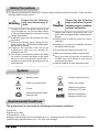
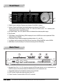
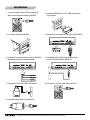
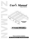
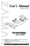
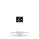
Safety Precautions
▣ The following precautions and directions are measures against possible accidents and injuries. Please read them
thoroughly before using this product.
Warning
Neglecting the following
may cause serious injury or
death.
▶ Opening the cover of the product while the power
cord is plugged into the Current/Voltage Sensor
(CVS) may cause electrocution of the user or critical
damage to the product.
▶ Handling the power cord with wet hands may cause
electrocution.
▶ During heavy lightning storms, unplug the main
power cord from the CVS to prevent possible system
damage and fire hazards.
▶ Plugging in the CVS Cable of the CVS into the
motherboard’s USB port may damage the
motherboard and CVS.
▶ If the current to be measured exceeds 10A (RMS),
use a cable or conductor that allows current greater
than the current to be measured to flow through it,
and always connect protective grounding prior to use
of this instrument.
Caution
Neglecting the following
may cause minor injuries,
degrade product conditions,
or cause malfunction.
▶ Operating the product in an extremely cold or hot
environment can degrade product performance and
life span.
▶ Allowing liquids to enter the product can result in
malfunction.
▶ Operating in a humid or non-ventilated environment
can reduce product life span.
▶ Do not place heavy objects on top of the CVS.
▶ Must use a well wrung-out cloth to clean the CVS.
▶ Using the product for purposes not specified by
ZALMAN may cause damage to other devices
connected to this product.
▶ Must be installed on an easily reachable location.
Symbols
Alternating current
Protective conductor terminal
Caution, risk of electric shock
Caution, risk of danger
CE mark
Federal Communications
Commission (FCC) mark
Nationally Recognized Testing
Laboratory mark
Restriction of Hazardous
Substances (RoHS) mark
Environmental Conditions
This product must be used under the following environmental conditions:
a) Indoor use;
b) Altitude up to 2,000m;
c) Temperature 5 ℃ to 40 ℃;
d) Maximum relative humidity 80% for temperatures up to 31 ℃ decreasing linearly to 50% relative humidity at 40 ℃;
e) MAINS supply voltage fluctuations up to ±10% of the nominal voltage.
※ The specifications of product may change without any prior notice to improve performance.
Features
1. Real time display of power consumption.
2. Four sensors for temperature monitoring and display.
3. Monitoring and control of one PWM fan and three standard fans.
4. Alarm system to notify non-operation of any of the fans.
5. Fan’s operation status indicated with animated propeller images.
Components
1. One ZM-MFC2
2. One CVS (Current/Voltage Sensor)
3. One Bracket / CVS Extension Cable
4. Four Temperature Sensors
5. Fan Cables - 3-Pin 2EA, 4-Pin 1EA, Y-Cable 1EA
6. Four ZM-MFC2 Installation Bolts
7. One Bracket Installation Bolts
8. One User’s Manual
ZM-MFC2 Specifications
Dimensions
147 x 87 x 42 (mm)
Power & Temperature Display
30~800W/ -9℃ ~ +99℃
Fan Compatibility
1 X 4-Pin (Supports fans with PWM function)
3 X 3-Pin (Supports fans with RPM output function)
Fan RPM Control
60~5940rpm
PWM Regulation Method (Fan No.4)
Voltage Control Method (Fan No.1~3)
Output Current
0.7A
Output Voltage
4~11V
Input Voltage
12VDC/+5VDC
CVS Specifications
Input
100-240V~,50/60 Hz, 10A
Bypass Output
100-240V~, 50/60Hz, 10A
Output
5V~, 0.03A
※ The specifications of product may change without any prior notice to improve performance.
Front Panel
Graphic Power Load Meter: Displays power between 30 to 800W in 4 stages.
Numeric Power Load Display: Numerically displays power between 30 and 800W.
(The Numeric Power Load Display will read“LLL”when an overflow occurs.“LLL”indicates power
loads beyond the unit’s measurable range.)
Fan Status Display: The Fan’s operation status is indicated with animated propeller images.
Fan Channels
RPM Display: During RPM Setting, RPM is displayed in units of 60RPM, and actual operational RPM is
displayed in units of 10RPM.
Temperature Display: Displays temperature readings between -9℃ and +99℃
Jog Wheel: Used for adjusting Fan RPM. RPM can be set from 1000 to 5940RPM in units of 60RPM.
Mode Button: Used for selecting a Fan Channel and saving the Fan RPM setting.
Back Panel
Standard Fans (Fan 1~3): 3-Pin fans that include the RPM output function can be connected for use.
PWM Fan (Fan 4): 4-Pin fan that includes the PWM function can be connected for use.
Temperature Sensing: Four temperature sensors can be connected.
CVS Terminal: Receives the measured values of the CVS.
Power Connector: Connects with the PSU’s 4-Pin connector.
※ The specifications of product may change without any prior notice to improve performance.
Installation
1. Turn the computer’s power OFF and unplug the
Main Power Cord before installing ZM-MFC2.
2. Install the ZM-MFC2 into a 5.25" ODD bay as shown
in the diagram.
3. Fix it in place with the use of Bolts.
4. Connect the Power Cable and Fan Cables to ZM-MFC2.
5. Connect the Temperature Sensor’s plug to ZM-MFC2,
and attach the sensors to desired locations.
6. Install the Bracket in the Enclosure, and connect
the CVS Extension Cable to ZM-MFC2.
7. Connect the CVS’s CVS Cable to the Bracket.
8. Connect the CVS’s AC Power Cord to the PSU.
9. Connect the Main Power Cord to the CVS.
※ The specifications of product may change without any prior notice to improve performance.
Connections
The Main AC Power Cord is not provided with ZM-MFC2.
※ The specifications of product may change without any prior notice to improve performance.
Operational Guidelines
Four channels of ZM-MFC2 detect fan RPM signals.
The Alarm will activate if a fan is not connected or if there is no RPM input signal for any of the channels.
To deactivate the Alarm, the Stand-By Mode (default setting: ON) of each unused channel must be deactivated.
1. Selecting a Channel/Deactivating Stand-By Mode
(1) Select a channel with the Mode Button (The selected channel will begin to flicker).
(2) Press the Jog Wheel to deactivate the selected channel’s Stand-By Mode. The fan image will turn off.
(3) Deactivate the Stand-By Mode of all unused channels as mentioned above.
Note: Deactivating the Stand-By Mode of all the channels will not deactivate other functions (Channel Output, RPM
Display, RPM Setting & Saving etc.)
2. RPM Setting and Saving
(1) Select a channel with the Mode Button.
(2) Set the RPM with the Jog Wheel. (Turning the Jog Wheel in clockwise motion will increase the RPM, and turning it
counter-clockwise will decrease the RPM)
(3) Press the Mode Button again to save the set value and to select the next channel.
(If nothing is input for 5 seconds, the ZM-MFC2 will automatically save the latest setting and leave the Setting Mode).
3. Initializing to Default Settings
Press the Mode Button for 3 seconds. (The entire display will be on for 1 second and all fans will be set to 1500 RPM)
Y-Cable Guidelines
Use of the Y-cable allows the operation of 2 fans with 1
channel.
Please read the following guidelines carefully before use.
(1) A 3-pin fan must be connected to the White Housing.
(2) The second fan must be connected to the Blue Housing.
(3) The fan speed cannot be controlled if a fan is connected to the Blue Housing with no fan connected to the White
Housing.
(4) The fan speed is controlled according to the speed of the fan connected to the White Housing, and the specifications of
the two fans must be identical.
Items to Check Before Reporting for Malfunction
1. Check to see that the CVS is properly connected to the ZM-MFC2 and PSU.
2. Check to see that all the cables are connected properly.
3. Check to see if pressing the Mode Button initializes the device to default settings.
4. Check the fans’ specifications.
(1) The RPM of 2-Pin Fans that do not output RPM signals cannot be controlled. Must use 3-Pin Fans that output 2 clock
pulses for each round.
(2) Connecting a 3-Pin Fan to the PWM 4-Pin connector will not allow RPM control.
5. If there are any problems with the fan, then noise will interfere with the RPM clock waves. This disrupts accurate RPM
control.
6. Fan RPM cannot be set higher than the fan’s specified value. If using a 3000RPM fan, then setting it to 5000RPM will not
cause the fan to operate at 5000RPM.
7. For fans with a specified minimum RPM, if the fan is set to a low RPM, there may be cases in which the fans stop and
restart rotating. This is not a defect of ZM-MFC2. You must set the RPM higher than the specified minimum RPM of the
fan.
※ The specifications of product may change without any prior notice to improve performance.
Zalman’s CNPS (Computer Noise Prevention System) Products
For a stable and noiseless system of the highest quality, use Zalman’s Ultra Quiet CPU Coolers, Ultra Quiet VGA Coolers,
Ultra Quiet Power Supplies, Heatpipe HDD Cooler, Fanless Northbridge Coolers, and Noiseless Case Fans.
Ultra Quiet CPU Cooler
CNPS9700 LED
Fanless Northbridge Cooler
ZM-NBF47
Ultra Quiet VGA Cooler
VF900-Cu LED
Silent Case Fan
ZM-F1, F2, F3
Ultra Quiet Power Supply
ZM600-HP
Heatpipe HDD Cooler
ZM-2HC2
International Safety and EMC Certifications
This device complies with part 15 of the FCC Rules. Operation is subject to the following two conditions: (1) This device
may not cause harmful interference, and (2) this device must accept any interference received, including interference that
may cause undesired operation.
Product Warranty (International)
Thank you for purchasing Zalman’s product.
Warranty - If this product has any defects, then Zalman guarantees that it can be exchanged within one (1) year from the
time of purchase.
* Product exchange is made with the reseller where the product was purchased.
For further inquiries, contact Zalman headquarters at www.zalman.co.kr or via e-mail to a representative.
There will be no exchanges in the following cases:
A) Violation of the Safety Precautions and the instructions in this manual.
B) Human fatality and/or property damage due to events of natural causes.
C) External case damage, electrical problems, and damage to components caused by careless mishandling.
Disclaimer
Zalman Tech Co., Ltd. is not responsible for any damages due to external causes, including but not limited to, improper
use, problems with electrical power, accident, neglect, alteration, repair, improper installation, or improper testing.
Contact Information
< Zalman Tech Co., Ltd. >
Homepage : www.zalman.co.kr
E-mail : [email protected]
< Zalman USA Inc. >
Homepage : www.zalmanusa.com
E-mail : [email protected]
※ The specifications of product may change without any prior notice to improve performance.