1
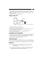
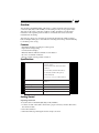
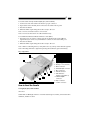
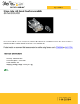
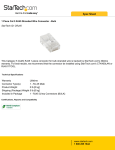
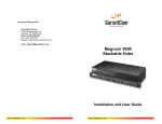
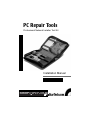
PC Repair Tools
Professional Network Installer Tool Kit
Installation Manual
CTK400LAN
1
Overview
The StarTech.com Professional LAN Installation Tool kit provides all the necessary tools
to install and test RJ45 networks in a compact, handy, carrying case. Tools included are:
a RJ45/11 Crimp tool, a 110/66 Impact Punch Tool, a wire stripper, several RJ45
connectors, and a RJ45 network cable tester with remote loopback plug (same as the
StarTech.com REMOTETEST tester).
Getting Started
Unpacking the CTK400LAN
This package should contain:
1 x Remote Cable Tester (in own carrying case, same as StarTech.com’s LANTESTPRO)
1 x Combo Crimper (same as StarTech.com’s RJ4511TOOL)
1 x Punch Down Tool
1 x Stripping Tool
30 x RJ11 Connectors
30 x RJ45 Connectors
24 x Boots for Cable Ends (various colors)
2 x Blades for Punch Down Tool
1 x Carrying Case
Building a Cable
Cutting Blade
Crimper 8-pin
Crimper 6-pin
1. Use the Combo Crimping tool to trim both ends of the cables by using the blade
closest to the handle. Be sure that both ends are cut square.
2. Use the trimming blade to strip the jacket off both ends of the cable. thus exposing the
individual color coded conductors.
3. Remove a length of jacket so that, when conductors are pushed all the way to the
front of the connectors, the jacket extends under the slot on the connector where the
crimping operation will hold it for strain relief.
4. Insert the conductors into the RJ45/RJ11 connector so that the blue conductor goes to
pin 1.
2
5. Insert the RJ45/RJ11 plug into the crimping tool as far as possible. There are two
modules: a 6-way one for RJ11 connectors (used on phone jacks) and an 8-way one for
RJ45 connectors used on computer jacks. Close the tool as firmly as you can to crimp
the plug into the cable.
6. Repeat steps 2- 5 for the other end of the cable.
Stripping Copper Pairs
Stripper
Punch down tool for use on 110/88 type of termination
1. Prepare the wire that you want to strip. Determine the appropriate stripper size by
reading the number shown as AWG or MM.
2. Open the tool by rotating the lock latch downward.
3. Place one end of your wire in the V-groove. Leave approximately 3/8 inch (1 cm) of
wire protruding beyond the edge of the tool.
4. Close and lock the stripper. Pull outward to strip off the insulating sheath.
5. Open the tool and remove the wire.
Note: Be sure that no strands of braid are loose, or they may cause shorts.
Seating Wires into Terminal Blocks
1. Put the wire into the V-groove, both beside colour coded tips, on the connecting block.
2. Use the punch down tool to establish a connection. Put the punch down tool above
the wire; then, punch the handle of the tool to insert the wire into the connecting
block, and the tool will cut the wire to the appropriate length.
3. Repeat these steps for additional wire seating.
Testing Connectivity
After you finished building up the RJ45/RJ11 connector, you can verify the integrity of
the connection done by using the remote cable tester provided in the CTK400LAN. Refer
to the cable tester’s user manual for more detailed information on its use and operation.
Appendix A
Networking: Networking consists of sharing information and services. Computer
networking provides the communication tools that allow users to
share information.
LAN: A local area network (LAN) refers to a combination of computer hardware and
transmission media that interconnect a relatively small number of machines. A
typical LAN usually does not exceed 10km in diameter.
3
MAN: A metropolitan area network (MAN) is larger than a LAN. It normally covers a
city-sized area and reaches a size several kilometers.
WAN: A wide area network (WAN) includes all networks. A WAN interconnects LASs
that may be located in different countries.
Appendix B
Copper Pairs
1. Most LANs employing copper wires use two pairs: one pair in each direction and all
twisted-pair are baseband.
2. Pairs must be twisted. This minimizes the EMI interface and radiation.
3. Pairs must be shielded - IBM type 1 and 2 use shielded pairs.
4. Typical interface - unshielded twisted pair (85-115 ohms at 10mhz) and shielded
twisted pair (150 ohms).
5. For UTP, RJ45, 8-pin modular telephone plugs dominate - 10BaseT standard
specifies them.
Coaxial Cable
Coaxial cable is used for both baseband and broadband LANs
1. Independence - the independence of coaxial cable is not based on size. That means, for
example, that bib cables do not necessarily have a low impedance.
2. Three common values of impedance - 50 ohms (for baseband Ethernet/802.3 LANs),
75 ohms (for broadband LANs/801.4) and 93 ohms (for ARCnet LANs)
3. EMI, radiation and bandwidth/bit rate
• EMI susceptibly and radiation are lower than TP.
• Conventional bandwidth is greater than 400mhz. It is usually limited by the
attached equipment.
• Data bit:10Mbps
4. Advantage of using optical fiber are:
• Security: No radiation. Avoids tapping.
• EMI: Not susceptible to electromagnetic interference.
Appendix C
Ethernet Comparison Chart
Media
Thicknet
Coaxial
Thinnet
Coaxial
10 BaseT
UTP
Data Rate
10
10
10
Maximum Segment Legth (m)
500
185
100
Network Span (m)
2500
925
Node Per Segment (m)
100
30100
Topology
Bus
Bus
Star
Wiring Testers
Remote Cable Tester for RJ45 RJ11 and BNC
Installation Manual
REMOTETEST
1
Overview
The StarTech.com REMOTETEST cable tester is a palm-sized unit with four kinds of
connectors: RJ45, RJ11, USB and BNC, for the testing of today’s most popular media.
This unit can be used to verify the condition of cables, both before and after their
installation. The separable passive module is connected to the remote end of the
installed network cabling.
The tester also offers easy operating; the user begins by testing by simply pushing a
button. Multiple LEDs give a clear indication of testing status and go off automatically,
to maximize power saving.
Features
• Detachable module for testing two remote points
• Open/Short wiring testing
• Connected wires display
• Ethernet 10Base2/10Base5 termination value detector
• No wire or termination indicator
• Wrong connection/Non-parallel connection
Specifications
Indicators
Battery Good/Battery Low
(Green/Yellow)
No Connection/No Terminator LED
(Yellow)
Non-Parallel/50 Ohm LED (Yellow)
Connected/25 Ohm LED (yellow)
Short LED (Red)
S, C/a, 2, 3, 4, 5, 6, 7, 8 LEDs (Yellow)
Connectors
RJ45 x 2, RJ11 x 2, USB A x 1, USB B x 1,
BNC x 1
Cable Length
200m for all connectors
Power
9V Alkeline battery
Size
145 x 86 x 26 mm (5.7 x 3.39 x 1.03")
Weight
185g (6.53 oz)
Getting Started
Operating Instruction
To test the cable not installed (RJ45, RJ11, USB, and BNC):
1. Connect one end of the cable to the master’s proper connector, and the other end to
the remote module.
2. Press the test button.
3. When the LEDs stop flashing the result is ready to be read.
2
To test the cables already installed (RJ45, RJ11, USB and BNC):
1. Connect one end of the cable to the master’s proper connector.
2. Separate the remote module, then connect it to the cable’s remote point.
3. Press the test button.
4. When the LEDs stop flashing the result is ready to be read.
Note 1: Do not connect the tester to a live circuit.
Note 2: Do not test more than one cable simultaneously.
To test Ethernet 10Base2/10Base5 terminator value (BNC):
1. Disconnect any one of the T-connectors from its attached node on the 10Base2
segment that you want to test, and link the T-connector to the testers BNC port.
2. Press the test button.
3. When the LEDs stop flashing the result is ready to be read.
Note 1: Before conducting the test, verify there isn’t any activity on the 10Base2 segment.
Note 2: If testing LED fails to light after pressing the test button, replace the battery.
Key components
7
3
1
4
6
B
2
C
A
5
1. Operating push button
2. Battery cover (on back)
3. BNC connector
4. Shielded RJ45 connector
5. RJ11 connector
6. USB B connector
7. LED indicator
(Refer to Appendix A)
A. Shielded RJ45
connector
B. RJ11 connector
C. USB A connector
How to Read the Results
Testing RJ45, RJ11, USB and BNC
Short Test
When LEDs for Short, S, and 3 are on and the tester beeps four times, it means the Wire
number 3, 4 and 5 are short.
3
Connected Test
When LEDs for Connected, S, and 1...8 LED are on and the tester beeps three times, it
means the shielding and indicated wires are pin-to-pin connected between cable’s two
ends. For instance, if a standard Ethernet 10BaseT unshielded twisted-paired cable (UTP)
are tested, the LEDs for Connected, Wire 1, 2, 3 and 6 will turn on.
Note: If there is only one wire connected inside a cable between the cable’s two ends, the
tester will state no wire connected.
Connected and Non-parallel Test
LEDs for both Connected and Non-parallel, and LEDs for Wire S, 1, 2, ...8 turn on and
the tester beeps twice, it means the shielding and indicated wires are connected between
cable’s two ends, but not pin-to-pin straight connection. It is possibly a wrong connection
cable or a cross-over cable.
Note: If there are only two wires connected inside a cable between the cable’s two ends,
the tester cannot detect whether these two wires are pin-to-pin connected or not. It only
indicates two wires connected.
No Connection Test
When the No Connection LED turns on and the tester beeps once, it means there is no
connection between the master and the remote module. It happens when no cable is
connected with the tester.
Testing BNC Connector
LED for Short, S and C
When LEDs for Short, S and C, turn on and the tester beeps four times, it means the
shield and the center of the BNC connector is short.
LED for 25 OHM, S and C
When the LEDs for the 25 OHM, S and C turn on and the tester beeps three times, it
means the tested cable it terminated with correct terminated resister value.
LED for 50 OHM, S and C
When the LEDs for 50 OHM, S and C turn on and the tester beeps twice, it means a
single ending terminated resister value is detected. It may be caused by a broken cable,
or the terminator at one end is not linked well.
LED for No Terminator
When the LED for No Terminator turns on and the tester beeps once, it means no resister
value detected between shielding and center. The cable is probably not terminated
(all open).
4
Appendix A - LED Indicators
The Remote Cable Tester has a total of 14 LEDs, 9 horizontal indicating each individual
wire inside a cable, and 5 vertical displaying a cable connection status. You can read the
result from the combination of lit horizontal and vertical LEDs.
• S (Yellow) Shielding
• C/1 (Yellow) Center of coaxial cable (BNC) or wire a of TP cable (RJ45), telephone cord
(RJ11) or USB
• 2, 3, 4, ...8 (Yellow) Wire 2, 3, 4, ...8
• Short (Red) Short condition between wires, or between shielding and center of BNC
connector.cable are detected.
• Connected or 25 Ohm (Green) A straight-through connection cable is detected. Or a
standard Ethernet 10Base2 and 10Base5 terminated with 25 Ohm cable is detected.
• Non-parallel or 50 Ohm A non-straight-through connection cable is detected. Or an
Ethernet 10Base2 and 10BAse5 cable with one end termination value (50 Ohm)
is detected.
• No connection/no terminator (Yellow) No cable or terminator is scanned.
• Battery good/battery low (Yellow/Green) It shows the battery status. If LED is green
the battery condition is good, if the LED is yellow the battery condition is poor.
Replace the old battery with a new one when the LED fails to remain lit during
normal operation.
Appendix B
UTP Colour Code
Pair 1
Pair 2
Pair 3
Pair 4
White-Blue (W-BL)
Blue (BL)
White-Orange (W-O)
Orange (O)
White-Green (W-G)
Green (G)
White-Brown (W-BR)
Brown (BR)
Wiring Scheme
T568A
1 W-G
2 G
3 W-O
4 BL
5 W-BL
6 O
7 W-BR
8 BR
T568B
1 W-O
2 O
3 W-G
4 BL
5 W-BL
6 G
7 W-BR
8 BR