1
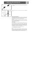
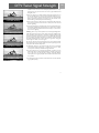
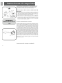
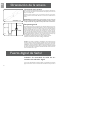
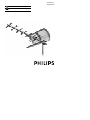
SDV9201/17
SDV9201K/17
EN
User manual
3
SP
Manual de utilizador
9
Contents
EN
2
3
Safety Instructions
4
Assembly and Installation
5
Aiming the Antenna
5
DTV Tuner Signal Strenght
8
Warranty
8
Technical Support
Safety Instructions
EN
WARNING INSTALLATION OF THIS PRODUCT NEAR POWER
LINES IS DANGEROUS. FOR YOUR SAFETY, KEEP LADDER AND
ANTENNA AWAY FROM POWER LINES. CONTACT MAY CAUSE
ELECTROCUTION
Antenna Grounding and Safety Warning
1. Outdoor antennas and lead-in conductors from antenna to a building, should
not cross over open conductors of electric light of power circuits.They should
be kept away from all circuits to avoid the possibility of accidental contact.
2. Each conductor of a lead-in from an outdoor antenna should be connected
with an antenna discharge unit. Antenna discharge units (or Lightning
Arrestors) should be located outside the building or inside the building
between the point of entrance of the lead-in and the TV, and as near as practical to the entrance of the conductors to the building.
IMPORTANT
READ
BEFORE
INSTALLATION
About the Design of Your Antenna
The design process of this antenna began in the very early days of DTV transmission, largely because of frustration with the selection of antennas on the market.The old antennas were all legacy technology from the 1950s. Popular thinking of the early days of DTV transmitting was “radio waves have not changed so
why should we use different antennas for DTV?” Radio waves have not changed
but our transmission system and performance expectations have. We designed
this antenna to be an integral part of the DTV transmission and reception chain.
It is designed to maximize the strengths and minimize the weakness of the new
ATSC system. It was designed to work with the DTV tuner and capture a more
stable signal so the DTV tuner can do its job with a minimum of effort and create a razor sharp and stable picture on your DTV.This antenna was not designed
by simulated theoretical physics; it was designed to work with the physics of the
real world, the real world of changing weather, cities and mountains.This antenna will work in areas where others completely fail or provide marginal results
with part time reception.
TO STATION
Note: For final installation and connection of your antenna, a dditional hard w a re may be re q u i red. B e fo re starting
assembly, please read through the instructions care f u l ly to
determine your specific re q u i re m e n t s .
3
Assembly and installation
EN
Assembly and installation instructions
Before assembling the antenna, take a moment to familiarize yourself with the
antennas’ construction. Notice that the boom of the antenna has a top and bottom. The horizontal elements are mounted to the top side of the boom. The
reflector on the other hand, does not have a specific top or bottom.
1. Extend the folded drive element by carefully folding the “wings” outward so
they are at 90 degrees to the boom. (fig.3)
fig. 3
2. Attach Transformer to bottom studs of drive elements with wing nuts and
washers. (fig.4)
3. Slide the reflector screen onto the boom from the rear until the screw holes
of the screen bracket line up with the holes on the top and bottom of the
boom.Attach the screen to the boom using two (2) 1-1/2” bolts, lockwashers
and wing nuts.
fig. 4
Tip:
To make it easier to fit when sliding the screen onto the boom, squeeze the top
and bottom of the screen towards each other.
4. Insert end caps at end of boom (fig. 5).
5. Attach the antenna to the mast: Assemble U-bolt to cross piece. Attach Ubolt assembly loosely to antenna, using saddle, lockwashers and nuts. insert
mast through U-bolt.Tighten nuts securely (fig.5) (Mast sold separately).
fig. 5
6. Connect 2 mast sections as shown in figure 6 (included in SDV9201K only)
fig.6
4
Aiming the Antenna
fig. 7
EN
7. Connect a good quality RG-6 coaxial cable to the transformer. Slide the
weatherproof boot over the connection firmly until it seals (fig. 7) (Cable sold
separately)
8. Attach cable standoff to mast as shown in figure 8 (included in SDV9201K
only)
fig. 8
Aiming the Antenna
Before permanently mounting the antenna for digital television (DTV) reception
it is a good idea to perform a quick sight survey to find the spot with the best
signal. Moving the antenna one way or another just a few feet can make a
tremendous difference in the success of the antenna installation.
WARNING – Installation of this product near power lines is dangerous. For your safety, keep ladder and antenna away from power lines.
Contact may cause electrocution.
Overview
DTV is a little different than analog TV.With analog TV peak signal strength was
the most important factor for good reception and creating a good picture.With
DTV peak signal strength is not the most important factor for good reception.
This means that our old methods for finding a location and aiming a TV antenna
will not give us the best results for DTV. In choosing a permanent location for
our DTV antenna we want to look at a couple of mounting locations.There are
two methods for testing for the best antenna location:
1. Terrestrial Digital receivers internal signal strength indicator.
2. Conventional Analog TV pointing method.
Tip:
Do not use a convention signal strength meter for installing a DTV antenna.
Chances are this will give you false information and cause the antenna not to
work reliably. Severe ghosting is the number one reason for DTV reception
problems. Most severe ghosting occurs in locations where there is plenty of signal strength. A conventional signal strength meter will find this location.
5
DTV Tuner Signal Strength
EN
DTV Tuner Signal Strength Indicator
If your DTV set top box or DTV tuner in your TV has a signal strength indicator (refer to that components user manual) you can utilize this feature for
selecting a location for installation and aiming the antenna.
1. Locate antenna in a high location with as few obstructions in front of, behind,
or to the sides of the antenna as possible. Optimally the antenna needs to be
at least 30 feet above the ground pointed directly in the “line of sight” of the
broadcast antenna (Line of sight means that there are not any obstructions
between the broadcast and receiving antenna such as buildings, water towers,
mountains or trees. Line of sight does not mean you need to be able to see
the broadcast antenna with your eye) If you are able to achieve this “line of
site installation and do not have severe multi-path problems such as in a very
dense high rise area, you will in most cases receive a good stable DTV and
Analog TV picture.
2. Connect the antenna to your DTV tuner with a good quality transmission
line.
3. Slowly rotate antenna on mounting mast in both directions until the highest
signal strength is achieved on the DTV tuner. Check all DTV channels to make
sure the signal is good on all channels you desire to receive from the DTV
broadcast tower that you are pointing at. If you have two DTV broadcast towers in two distinct directions and are not able to receive all DTV stations
broadcasting in your area install the antenna with a rotor.
4. Watch DTV channel for a few minutes to make sure picture is consistently
stable without freezing, disappearing or breaking up. If picture is stable, securely mount antenna per enclosed mounting instructions.
5. For best results, do not run signal through diplexers or splitters, run new RG6
coaxial cable from antenna location directly to your DTV receiver. If you have
a cable run of more than 100 feet or need to run through diplexers and/or
splitters use a signal preamplifier that is installed as close to the antenna as
possible.
6. To avoid signal loss, do not attach the coaxial cable to the mast, use standoffs
(fig. 7) (sold separately).
Analog TV Pointing Method
This method uses a conventional analog TV to chose the best spot for a DTV
antenna.
1. Place antenna in as high location with as few obstructions in front of behind
or to the sides of the antenna as possible. Optimally the antenna needs to be
30 feet above the ground pointed directly in the “line of sight” of the broadcast antenna (Line of sight means that there are not any obstructions between
the broadcast and receiving antenna such as buildings, water towers, mountains or trees. Line of sight does not mean you need to be able to see the
broadcast antenna with your eye) If you are able to achieve this “line of site
6
DTV Tuner Signal Strength
EN
installation and do not have severe multi-path problems such as in a very
dense high rise area, you will in most cases receive a good stable DTV and
Analog TV picture.
2. Tune your analog TV to a UHF TV channel (channel 14 or higher) that is on
the same broadcast tower or tower location as the DTV stations you are trying to receive. If you do not know this information you can call your local TV
station’s engineering department and ask them. If you have internet access,
Antennaweb.org is also helpful. (www.antennaweb.org)
Picture With Ghosting
3. Slowly rotate antenna or walk location area with antenna while monitoring
your analog TV. Find the location that has a stable picture with the least
amount of ghosting.
4. Very often, ghosting can be minimized if you rotate your antenna until the picture improves. Unfortunately, sometimes there is no solution for the problem
due to surrounding terrain/obstructions. We are looking for a picture that is
clear and free of ghosting.
Snow in Analog Picture
Ghosting - This is a very common problem in areas with large buildings, hills or
valleys. The signal bounces off of various surfaces and creates multiple images.
This is sometimes called “multi-path” to describe the multiple signals that reach
the antenna. In extreme cases, you may see six or more distinct clear images side
by side overlapping each other. The problem can usually be resolved by moving
the antenna mounting position six feet to the left or right and/or raising your
antenna higher to receive a more direct signal.
Do not worry about snow in the analog picture; this is not a problem for DTV.
Find a location where the analog TV has the least amount of ghosting, and color
in the picture with the audio clearly heard.
Impulse Noise in Analog
5. Watch DTV channel for a few minutes to make sure picture is consistently
stable without freezing, disappearing or breaking up. If picture is stable,
securely mount antenna per enclosed mounting instructions.
6. For best results, do not run signal through diplexers or splitters, run new
RG6 coaxial cable from antenna location directly to your DTV receiver. If you
have a cable run of more than 100 feet or need to run through diplexers
and/or splitters use a signal preamplifier that is installed as close to the antenna as possible.
Good Clear Picture
7. To avoid signal loss, do not attach the coaxial cable to the mast, use stand offs
(fig. 7) (sold separately)
7
Warranty
EN
Limited One-Year Warranty
Philips warrants that this product shall be free from defects in material, workmanship and assembly, under normal use, in accordance with the specifications
and warnings, for one year from the date of your purchase of this product.This
warranty extends only to the original purchaser of the product, and is not transferable. To exercise your rights under this warranty, you must provide proof of
purchase in the form of an original sales receipt that shows the product name
and the date of purchase. For customer support or to obtain warranty service,
please call 919-573-7863. THERE ARE NO OTHER EXPRESS OR IMPLIED
WARRANTIES. Philips’ liability is limited to repair or, at its sole option, replacement of the product. Incidental, special and consequential damages are disclaimed where permitted by law. This warranty gives you specific legal rights. You
may also have other rights that vary from state to state.
Technical Support
Technical Support
For technical support send an email with the model number of the product and
a detailed description of your problem to:
Email: [email protected]
©2006
Accessories Service Center
Philips
Accessories and Computer Peripherals,
Ledgewood, NJ 07852 USA
Manufactured in USA
Printed in USA
8
Contenido
10
Instrucciones de seguridad
11
Montaje e Instalación
12
Orientación de la antena
13
Fuerza digital de Señal
15
Garantía
15
Asistencia Técnica
EN
9
Instrucciones de seguridad
EN
LA ADVERTENCIA LA INSTALACION DE ESTE PRODUCTO CERCA DE
LINEAS DE FUERZA ES PELIGROSA. PARA SU SEGURIDAD, MANTENGA ESCALERA Y ANTENA LEJOS DE LINEAS DE FUERZA. LA ELECTROCUCION DE LA CAUSA DEL MAYO DEL CONTACTO.
Puesta a tierra de la antena y advertencia de
seguridad
1. Las antenas de exterior y los conductores que ingresan a un edificio desde
la antena no deberían cruzarse con conductores abiertos de iluminación o
circuitos de energía eléctrica. Deberían mantenerse alejados de todos los circuitos para evitar la posibilidad de un contacto accidental.
2. Cada conductor de un cable de entrada desde una antena de exterior
debería conectarse a una unidad de descarga de antena. Las unidades de
descarga de antena (o supresores de sobretensiones de origen atmosférico)
deberían estar ubicados fuera del edificio o, dentro del edificio, entre el punto
de ingreso del cable de entrada y el televisor, y tan cerca como sea posible
de la entrada de los conductores al edificio.
IMPORTANTE
LEER ANTES DE INSTALAR
A LA ESTACIÓN
Acerca del diseño de la antena
El proceso de diseño de esta antena comenzó en los muy tempranos días de la
transmisión de televisión digital, en gran parte debido a la frustración que causaba la selección de las antenas disponibles en el mercado. Las viejas antenas eran
todas de tecnología heredada de los años cincuenta. El pensamiento popular de
los primeros días de la transmisión de televisión digital era: “las ondas de radio
no han cambiado, entonces, ¿por qué deberíamos emplear antenas diferentes
para televisión digital?” Las ondas de radio no han cambiado, pero los sistemas
de transmisión y las expectativas de calidad funcional sí han cambiado. Hemos
diseñado esta antena para que sea una parte integral de la cadena de transmisión
y recepción de televisión digital. Está diseñada para maximizar las fortalezas y
minimizar las debilidades del nuevo sistema ATSC (Advanced Television Systems
Committee, Comité de Sistemas de Televisión Avanzados, de EE.UU.). Fue diseñada para trabajar con el sintonizador de televisión digital y capturar una señal más
estable de tal forma que el sintonizador de televisión digital pueda cumplir su
función con un mínimo de esfuerzo y crear una imagen nítida y estable en el televisor digital. Esta antena no fue diseñada mediante física teórica simulada; fue diseñada para trabajar con la física del mundo real, el mundo real de clima cambiante, de ciudades y montañas. Esta antena funciona en áreas donde otras fallan
completamente u ofrecen resultados marginales con recepción solamente
durante parte del tiempo.
Instrucciones de montaje e instalación
10
Montaje e Instalación
EN
Antes de ensamblar la antena, tómese un momento para familiarizarse con su
construcción. Note que el larguero de la antena tiene una parte de arriba y una
parte de abajo. Los elementos horizontales están montados en el lado de arriba
del larguero. El reflector, por el contrario, no tiene una parte de arriba ni una
parte de abajo específicas.
1. Extienda el elemento excitador plegado, doblando cuidadosamente las “alas” hacia
afuera de modo que queden a 90º con respecto al larguero (ver Figura 3).
fig. 3
2. Fije el transformador a los espárragos inferiores de los elementos excitadores con tuercas mariposa y arandelas (ver Figura 4).
3. Deslice la rejilla reflectora sobre el larguero desde la parte de atrás hasta que
los agujeros de tornillo del soporte de la rejilla estén alineados con los agujeros ubicados en las partes de arriba y de abajo del larguero. Fije la rejilla al
larguero usando los dos (2) pernos de 1 1/2 pulgadas (38 mm), arandelas de
presión y tuercas mariposa.
Consejo: Para facilitar el calce cuando deslice la rejilla sobre el larguero, apriete
las partes de arriba y de abajo de la rejilla una contra la otra.
fig. 4
fig. 5
4. Inserte los tapones de terminación en los extremos del larguero (ver Figura 6).
5. Conecte un cable coaxial de tipo RG-6 de buena calidad al transformador.
Deslice firmemente la vaina a prueba de agua sobre la conexión hasta que
selle (ver Figura 5) (el cable se vende separadamente).
6. Fije la antena al mástil: monte el perno en U a la pieza en cruz.Fije flojamente
el perno en U a la antena empleando la pieza de fijación, arandelas de presión y tuercas, e inserte el mástil a través del perno en U. Ajuste las tuercas
firmemente (ver Figura 6) (el mástil se vende separadamente).
fig. 6
11
Orientación de la antena
EN
Orientación de la antena
Antes de montar permanentemente la antena para recepción de televisión digital, es una buena idea realizar un reconocimiento visual rápido para encontrar el
lugar con la mejor señal.
Cambiar la antena de lugar, en una u otra dirección, sólo unos pocos metros,
puede representar una tremenda diferencia en el éxito de la instalación de la
antena.
fig. 7
SDV9201K sólo
ADVERTENCIA: la instalación de este producto cerca de líneas de
energía es peligrosa. Para su seguridad, mantenga la escalera y la antena lejos de líneas de energía. El contacto puede causar electrocución.
Perspectiva general
fig. 8
La televisión digital es un poco diferente de la televisión analógica. Con la televisión analógica, la máxima intensidad de señal era el factor más importante para
la buena recepción y para crear una buena imagen. Con la televisión digital, la
máxima intensidad de señal no es el factor más importante para una buena
recepción. Esto significa que nuestros viejos métodos para encontrar una ubicación y orientar una antena de televisión no nos darán los mejores resultados
para la televisión digital. Al elegir una ubicación permanente para la antena de
televisión digital, tenemos que observar un par de ubicaciones de montaje. Hay
dos métodos para probar cuál es la mejor ubicación de la antena:
1. Indicador de intensidad de señal de receptores digitales terrestres.
2. Método de orientación con televisor analógico convencional.
Consejo: No emplee un medidor de intensidad de señal convencional para
instalar una antena de televisión digital. Es probable que le dé información falsa
y haga que la antena no funcione confiablemente. La razón número uno de los
problemas de recepción en televisión digital es el efecto fantasma severo. La mayoría de los efectos fantasma severos ocurren en ubicaciones donde la intensidad
de señal es muy elevada. Un medidor de intensidad de señal convencional encontraría una ubicación de ese tipo.
Fuerza digital de Señal
Indicador de intensidad de señal de sintonizador de televisión digital
Si su receptor decodificador de televisión digital o el sintonizador de televisión
digital de su televisor tienen un indicador de intensidad de señal (consulte el
12
Fuerza digital de Señal
SP
manual del usuario de esos componentes), puede utilizar esta característica para
elegir una ubicación para instalar la antena y para orientarla.
1. Ubique la antena en un lugar elevado con tan pocas obstrucciones como sea
posible frente a la antena, detrás de ella o a sus costados. Lo óptimo es que
la antena esté al menos 30 pies (9 m) por encima del suelo, directamente en
la “línea visual” de la antena emisora de televisión (Línea visual significa que
no haya ninguna obstrucción entre la antena emisora y la antena receptora,
como edificios, torres de agua, montañas o árboles. Línea visual no significa
que pueda verse la antena emisora.). Si puede conseguir esta instalación en
“línea visual” y no tiene severos problemas de trayectoria múltiple, como en
un área con mucha densidad de edificios altos, en la mayoría de los casos
recibirá una imagen de televisión digital y analógica buena y estable.
2. Conecte la antena al sintonizador de televisión digital con una línea de transmisión de buena calidad.
3. Gire lentamente la antena sobre el mástil de montaje en ambos sentidos
hasta que se alcance la intensidad de señal máxima en el sintonizador de televisión digital.Verifique todos los canales de televisión digital para asegurarse
de que la señal sea buena en todos los canales que desee recibir desde la
torre de emisión de televisión digital a la que esté apuntando. Si hay dos torres de emisión de televisión digital en distintas direcciones y no puede recibir
todas las estaciones de televisión digital que se emiten en su área, instale la
antena con un rotor.
4. Mire el canal de televisión digital durante unos pocos minutos para asegurarse de que la imagen sea consistentemente estable, sin congelamiento,
desaparición ni ruptura. Si la imagen es estable, monte firmemente la antena
según las instrucciones de montaje que se incluyen.
5. Para obtener los mejores resultados, no encamine la señal a través de diplexores o divisores; instale cable coaxial nuevo de tipo RG-6 desde la ubicación
de la antena directamente hasta su receptor de televisión digital. Si tiene un
recorrido de cable de más de 100 pies (30 m) o necesita pasar a través de
diplexores y/o divisores, emplee un preamplificador de señal instalado tan
cerca de la antena como sea posible.
6. Para evitar pérdidas de señal, no fije el cable coaxial al mástil; emplee soportes
separadores (ver Figura 7) (se venden por separado).
Método de orientación con televisor analógico
Este método emplea un televisor analógico convencional para elegir el mejor
lugar para una antena de televisión digital.
1. Coloque la antena en un lugar elevado, con tan pocas obstrucciones como
sea posible frente a la antena, detrás de ella o a sus costados. Lo óptimo es
que la antena esté al menos 30 pies (9 m) por encima del suelo directamente
en la “línea visual” de la antena emisora de televisión (Línea visual significa
que no haya ninguna obstrucción entre la antena emisora y la antena receptora, como edificios, torres de agua, montañas o árboles. Línea visual no sig13
Fuerza digital de Señal
SP
nifica que pueda verse la antena emisora.). Si puede conseguir esta instalación
en “línea visual” y no tiene severos problemas de trayectoria múltiple, como
en un área con mucha densidad de edificios altos, en la mayoría de los casos
recibirá una imagen de televisión digital y analógica buena y estable.
Picture With Ghosting
2. Sintonice el televisor analógico en un canal de televisión UHF (ultra high frequency, frecuencia ultra alta) (canal 14 ó más alto) que esté en la misma torre
emisora o en la misma ubicación de torre que las estaciones de televisión
digital que esté tratando de recibir. Si no conoce esta información, puede llamar al departamento de ingeniería de la estación de televisión local y preguntarles. Si tiene acceso a Internet, Antennaweb.org también es útil
(www.antennaweb.org).
3. Gire lentamente la antena o camine por el área de ubicación con la antena
mientras controla el televisor analógico. Encuentre la ubicación que tenga
una imagen estable, con la menor cantidad de efecto fantasma.
Snow in Analog Picture
Impulse Noise in Analog
4. Muy a menudo, el efecto fantasma puede minimizarse si se gira la antena
hasta que la imagen mejore. Desafortunadamente, a veces no hay solución al
problema debido a las características del terreno circundante y a las obstrucciones existentes. Estamos buscando una imagen que sea clara y libre de
efecto fantasma.
Efecto fantasma: éste es un problema muy común en áreas con grandes edificios, cerros o valles. La señal rebota en varias superficies y crea múltiples imágenes. Esto se llama a veces “trayecto múltiple” para describir las múltiples
señales que llegan a la antena. En casos extremos, se pueden ver seis o más imágenes claras distintas lado a lado, sobreponiéndose una a la otra. El problema
puede resolverse usualmente moviendo la posición de montaje de la antena unos
seis pies (dos metros) a la izquierda o a la derecha y/o elevando la antena para
recibir una señal más directa.
No se preocupe por el efecto nieve en la imagen analógica; no representa un
problema para la televisión digital. Encuentre una ubicación donde la imagen en
el televisor analógico tenga la menor cantidad de efecto fantasma y donde,
además, la imagen tenga color y el audio se escuche claramente.
5. Mire el canal de televisión digital durante unos pocos minutos para asegurarse
de que la imagen sea consistentemente estable, sin congelamiento, desaparición ni ruptura. Si la imagen es estable, monte firmemente la antena según las
instrucciones de montaje que se incluyen.
Good Clear Picture
6. Para obtener los mejores resultados, no encamine la señal a través de diplexores o divisores; instale cable coaxial nuevo de tipo RG-6 desde la ubicación
de la antena directamente hasta su receptor de televisión digital. Si tiene un
recorrido de cable de más de 100 pies (30 m) o necesita pasar a través de
diplexores y/o divisores, emplee un preamplificador de señal instalado tan
cerca de la antena como sea posible.
7. Para evitar pérdidas de señal, no fije el cable coaxial al mástil; emplee soportes
separadores (ver Figura 7) (se venden por separado).
14
Garantía
SP
Garantía limitada por un año
Philips garantiza que este producto carece de defectos de material, manufactura
o armado, bajo uso normal y de acuerdo con las especificaciones y advertencias,
por el plazo de un año a partir de la fecha de compra de este producto. Esta
garantía cubre únicamente al comprador original del producto y no es transferible. Para ejercer sus derechos bajo esta garantía, debe proporcionar una prueba
de compra mediante una factura original que muestre el nombre del producto y
la fecha de compra. Por atención al cliente o para obtener servicio de garantía,
sírvase llamar al 866-892-4765. NO EXISTEN OTRAS GARANTÍAS IMPLÍCITAS
O EXPLÍCITAS. Las obligaciones de Philips se limitan a la reparación o, a su sola
opción, al reemplazo del producto. No se aceptan reclamos por daños incidentales, especiales e indirectos, de acuerdo a lo permitido por la ley. Esta garantía
le otorga a usted derechos legales específicos. Usted también tener otros derechos que pueden variar de estado a estado.
Asistencia Técnica
Asistencia Técnica
Correo electrónico:
[email protected]
©2006
Centro de Servicio de Accesorios
Philips
Accessories and Computer Peripherals,
Ledgewood, NJ 07852 USA
Hecho en EE.UU.
Imprimido en EE.UU.
15
Specifications are subject to change without notice
Trademarks are property of Philips Accessories and Computer Peripherals
2006© Philips Accessories and Computer Peripherals, Ledgewood, NJ USA
313520700014
www.philips.com