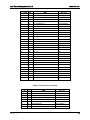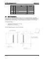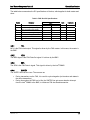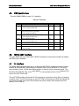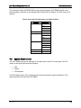
1
Intel® Remote Management Module 2 Technical Product Specification Revision 1.0 March, 2007 Enterprise Platforms and Services Division - Marketing Revision History Intel® Remote Management Module 2 Revision History Date March, 2007 Revision Number 1.0 Modifications First release Disclaimers Information in this document is provided in connection with Intel® products. No license, express or implied, by estoppel or otherwise, to any intellectual property rights is granted by this document. Except as provided in Intel's Terms and Conditions of Sale for such products, Intel assumes no liability whatsoever, and Intel disclaims any express or implied warranty, relating to sale and/or use of Intel products including liability or warranties relating to fitness for a particular purpose, merchantability, or infringement of any patent, copyright or other intellectual property right. Intel products are not intended for use in medical, life saving, or life sustaining applications. Intel may make changes to specifications and product descriptions at any time, without notice. Designers must not rely on the absence or characteristics of any features or instructions marked "reserved" or "undefined." Intel reserves these for future definition and shall have no responsibility whatsoever for conflicts or incompatibilities arising from future changes to them. The Intel® Remote Management Module 2 may contain design defects or errors known as errata which may cause the product to deviate from published specifications. Current characterized errata are available on request. Intel, Pentium, Itanium, and Xeon are trademarks or registered trademarks of Intel Corporation. *Other brands and names may be claimed as the property of others. Copyright © Intel Corporation 2007. All rights reserved. ii Revision 1.0 Intel® Remote Management Module 2 Table of Contents Table of Contents 1. Introduction .......................................................................................................................... 1 2. Product Overview................................................................................................................. 1 3. 4. 2.1 Virtual Presence....................................................................................................... 1 2.2 Firmware Feature Set .............................................................................................. 1 2.3 Web Front-end ......................................................................................................... 2 2.4 Virtual Media ............................................................................................................ 2 2.5 Remote Console ...................................................................................................... 3 2.6 Hardware Feature Set.............................................................................................. 3 2.7 Physical Dimensions................................................................................................ 7 Board Architecture ............................................................................................................... 8 3.1 Media Independent Interface (MII) ........................................................................... 8 3.2 USB 2.0 (high-speed) Interface................................................................................ 9 3.3 IPMB Connections ................................................................................................... 9 3.4 15-bit DVO Video Source......................................................................................... 9 3.5 Intel ® ASMI Connector .......................................................................................... 10 3.5.1 BMC_FML_0 Interface........................................................................................... 10 3.5.2 FML Connection..................................................................................................... 10 3.5.3 NIC_FML_1 ........................................................................................................... 10 3.6 8-MB SDRAM Video Frame Buffer Chip................................................................ 11 3.7 32-MB SDRAM System Memory ........................................................................... 11 3.8 8-MB Flash ............................................................................................................ 11 Electrical Specifications .................................................................................................... 12 4.1 3.3 V Auxiliary Operation ....................................................................................... 12 4.2 Power System ........................................................................................................ 12 4.3 DC Specifications .................................................................................................. 12 4.4 FML Bus Specifications.......................................................................................... 12 4.4.1 MCL ....................................................................................................................... 13 4.4.2 MDA ....................................................................................................................... 13 4.4.3 SDA ....................................................................................................................... 13 4.4.4 SINTEX .................................................................................................................. 13 4.5 IPMB Specifications ............................................................................................... 14 4.6 16550 UART Interface ........................................................................................... 14 Revision 1.0 iii List of Figures 4.7 MII Interface ........................................................................................................... 14 4.8 DVO Video and DDC/EDID Specifications............................................................. 15 4.8.1 DVO Interface ........................................................................................................ 15 4.8.2 Supported Video Resolutions and Refresh Rates .................................................. 16 4.9 5. Intel® Remote Management Module 2 System Reset Control ............................................................................................ 17 Network Connections and Authentication ....................................................................... 18 5.1 5.1.1 Network Connectivity ............................................................................................. 18 Supported Traffic ................................................................................................... 18 Glossary..................................................................................................................................... 19 List of Figures Figure 1. Frequency Relationships ............................................................................................. 16 List of Tables Table 1. Connector Pin-out, Side A .............................................................................................. 4 Table 2. Connector Pin-out, Side B .............................................................................................. 5 Table 3. FML Bus DC Specifications .......................................................................................... 13 Table 4. I2C Interface .................................................................................................................. 14 Table 5. DVO Bus DC Specifications.......................................................................................... 15 Table 6. Supported Video Resolutions and Refresh Rates ........................................................ 17 iv Revision 1.0 Intel® Remote Management Module 2 1. Introduction Introduction This Technical Product Specification (TPS) provides details about the architecture and feature set of the Intel® Remote Management Module 2 (Intel® RMM2). This document does not replace the Intel RMM2 Users Guide, but provides enhanced information to assist with understanding and learning more about specific features of the board. 2. Product Overview The Intel RMM2 is a 2.25-inch x 2.75-inch printed circuit board. When installed onto the Intel® RMM connector on Intel® server boards, it provides an increased level of manageability over the basic server management available to the server board. Designed to work with the Baseboard Management Controller (BMC), this small form-factor mezzanine card enables graphical server control from anywhere, at anytime. 2.1 Virtual Presence The Intel® RMM2 provides Virtual Presence (Remote Console) at the host server. This presence includes keyboard / video / mouse (KVM) redirection over Transmission Control Protocol / Internet Protocol (TCP/IP) using an Ethernet network port dedicated for remote management. The keyboard, video, and mouse of the remote server are available to the administrator from any network location, regardless of the state of the server (OS loading, running, or not responding (blue screen), Pre-OS BIOS boot and setup, etc). The dedicated Ethernet controller supports Out Of Band (OOB) access. In other words, it runs separately from the OS and the BIOS. This separation allows the Intel RMM2 to operate continuously, thus supporting 24 X 7 management of the system. The management traffic does not share network bandwidth with the host system software. 2.2 Firmware Feature Set Intel® RMM2 Virtual Presence over Remote Console: Keyboard/Video/Mouse (KVM) redirection over TCP/IP Intel RMM2 Web server supporting HTTPS or HTTP Automatically senses video resolution for best possible screen display Intel RMM2 Virtual Media: USB remote storage redirection over TCP/IP, up to two mass storage devices at a time Intel RMM2 Virtual Presence over Web Front-end: Power and Reset Control over TCP/IP Interaction with the BMC for support of Intelligent Platform Management Interface (IPMI) 2.0 Support for a dedicated 10/100 Out of Band (OOB) Management LAN channel Local and Remote Configuration Utilities for Microsoft Windows* and Linux* Firmware upgrade capabilities Revision 1.0 1 Product Overview 2.3 Intel® Remote Management Module 2 Highest Security Standards using up to 256 bit SSLv3, Certificate Management, Event Logging and State-of-the-Art Authentication Methods Web Front-end The Intel® RMM2 module features an embedded operating system and applications offering a variety of standardized interfaces. The interfaces are accessed using the TCP/IP protocol family, thus they can be accessed using the built-in Ethernet adapterr. The Intel® RMM2 Web Front-end is a Graphical User Interface (GUI). It offers convenient and secure access to Open the Remote Console Virtual Media System Health User Management KVM Settings Device Settings Intel RMM2 Maintenance information Using a standard web browser on the administrator’s client computer, the Intel RMM2 Web GUI provides Virtual Presence to the server. It offers the user the ability to: Obtain detailed system information Perform virtual media transfers Control power and reset the server In addition, the Intel® RMM2 allows the user to open a Remote console, see the screen of the target system and work with all applications as if he/she was seated at the system. All network communication with the Intel® RMM2 is secured using industry standard authentication, encryption, and access control mechanisms. Access to the Intel RMM2 Web Console is controlled by a user-based security system. 2.4 Virtual Media The Intel® RMM2 provides Virtual Media, which is USB remote storage redirection over TCP/IP, using the dedicated LAN interface. Administrators use Intel® RMM Virtual Media to: 2 Upload a floppy image to the Intel® RMM2, maximum size of 1.44 MB. Access a CD-ROM / DVD-ROM image on a Windows Share (SAMBA). Redirect CD-ROM / DVD-ROM drives, hard drives, or other mass storage medium, that is physically local to the administrator’s client computer, to appear as USB mass storage device on the target server. Additional client software is available for Windows*. Revision 1.0 Intel® Remote Management Module 2 Product Overview Once mounted, the media that is remote to the server appears local to the server. This allows administrators to install software or drivers on, or boot the server from the remote media. Intel® RMM2 - Virtual Media can be used to complete these actions: Install a new operating system on a target server Install an operating system upgrade on a target server Repair damaged operating system installs Transfer files to and from the target server to a remote location Flash BIOS or other firmware by use of bootable DOS storages The Intel® RMM2 Virtual Media offers to redirect two drives at a time which makes it even more comfortable to perform remote OS installations and allows access to use additional driver disks during OS installation. The ability to recover from a system hard drive crash to a known good state is also provided by the combination of Intel® RMM2 Virtual Media and Intel RMM2 Virtual Server Control. 2.5 Remote Console The Remote Console is the redirected screen, keyboard and mouse of the remote host system where the Intel® RMM2 module is installed. To use the Remote Console window of your managed host system, the browser must include a Java* Runtime Environment plug-in. If the browser has no Java support, such as with a small handheld device, the user can maintain the remote host system using the administration forms displayed by the browser. The Remote Console window is a Java Applet that establishes its own TCP connection to the Intel RMM2 module. The protocol that is run over this connection is RFB (Remote Frame Buffer Protocol), not HTTP nor HTTPS Starting the Remote Console opens a new window to display the screen content of the host system. The Remote Console acts as if the administrator was sitting directly in front of the screen of his/her remote system. That means keyboard and mouse can be used in the usual way. 2.6 Hardware Feature Set KIRA100 ARM 9 Processor at 200 MHz Dedicated Out-of-Band (OOB) 10/100Mbit Ethernet Network Interface Chip 32 MB CPU SDRAM 8 MB VSC SDRAM (Flash Memory) USB 2.0 High Speed Interface 15-bit DVO Interface Video input at up to 1600 X 1200 Resolution at 60 Hz High Speed Fast Management Link (FML) Interface to BMC IPMB (Intelligent Platform Management Bus) LPC (Low Pin Count) Revision 1.0 3 Product Overview Intel® Remote Management Module 2 The Intel® RMM2 connects to the Intel RMM connector on the Intel server board. The Intel RMM connector is based on the Advanced Server Management Interface (Intel® ASMI) specification. The Intel® RMM2 uses a sub-set of the connector’s pins. It connects to the following interfaces: IPMB DDC DVO RS232 FML 0 or FML 1 MII USB Table 1. Connector Pin-out, Side A Pin Side A 1 4 Pin 1 Signal NC_RESERVED Intel® RMM NO CONNECT 2 3 LPC_SYSRST_N SYSRST# 3 5 GND GND 4 7 NC RESERVED NO CONNECT 5 9 NC RESERVED NO CONNECT 6 11 GND GND 7 13 GND GND 8 15 USB1_P D+ 9 17 USB1_N D- 10 19 GND GND 11 21 VCC 3.3V +3.3V 12 23 LAD0 LAD0 13 25 LAD1 LAD1 14 27 VCC 3.3V +3.3V 15 29 LCLK (33Mhz) LCLK (33Mhz) 16 31 VCC 3.3V +3.3V 17 33 NIC_FML1_MDA (Module Master) NIC_FML1_MDA 18 35 NIC_FML1_SDA (Module Master) NIC_FML1_SDA 19 37 NIC_FML1_MCL (Module Master) NIC_FML_MCL 20 39 NIC_FML1_SINTEX (Module Master) NIC_FML_SNTX 21 41 VCCa 3.3Aux +3.3V AUX 22 43 EMP/SOL_SERIAL_DSR RSER_DSR 23 45 EMP/SOL _SERIAL_RTS RSER_RTS 24 47 EMP/SOL_SERIAL_CTS RSER_CTS 25 49 EMP/SOL _SERIAL_DCD RSER_DCD 26 51 EMP/SOL _SERIAL_RI RSER_RI 27 53 EMP/SOL _SERIAL_TX RSER_TX 28 55 VCCa 3.3Aux +3.3V AUX 29 57 LCDCNTL[3] – PIXEL CLK VDCLK Revision 1.0 Intel® Remote Management Module 2 Product Overview Pin Side A 30 Pin 59 GND Signal Intel® RMM GND 31 61 NC RESERVED_3 NO CONNECT 32 63 NC_RESERVED_4 NO CONNECT 33 65 GND GND 34 67 LCDCNTL[0] – DV_VS VSYNC 35 69 NC_RESERVED_8 C NO CONNECT 36 71 GND GND 37 73 LCDDATA23 LCDDATA23 38 75 LCDDATA22 LCDDATA22 39 77 LCDDATA21 LCDDATA21 40 79 LCDDATA20 LCDDATA20 41 81 LCDDATA19 LCDDATA19 42 83 GND GND 43 85 MAN LAN type 1 ML_TYPE1 44 87 MAN LAN type 2 ML_TYPE2 45 89 NC_RESERVED_9 C_TRST_IN# 46 91 RESERVED for Future Voltage Rail #2 C_TMS 47 93 MII_MDC MDC 48 95 MII_COL COL 49 97 GND GND 50 99 MII_TXER TXERR 51 101 MII_MDIO MDIO 52 103 GND GND 53 105 MII_RXD3 RXD3 54 107 MII_RXD2 RXD2 55 109 GND GND 56 111 MII_RXD1 RXD1 57 113 MII_RXD0 RXD0 58 115 GND GND 59 117 MII_RXCLK RXCLK 60 119 MII_RXDV RXDV Table 2. Connector Pin-out, Side B Pin Revision 1.0 1 Pin 2 GND Signal GND Intel® RMM 2 4 NC RESERVED NO CONNECT 3 6 NC RESERVED NO CONNECT 4 8 GND GND 5 10 GND GND 6 12 NC RESERVED NO CONNECT 7 14 NC RESERVED NO CONNECT 8 16 GND GND 5 Product Overview Intel® Remote Management Module 2 Pin 6 9 Pin 18 GND Signal GND Intel® RMM 10 20 NC_RESERVED_1 NO CONNECT 11 22 NC_RESERVED_2 NO CONNECT 12 24 GND GND 13 26 LFRAME LFRAME 14 28 LAD2 LAD2 15 30 LAD3 LAD3 16 32 VCC 3.3V +3.3V 17 34 IPMB_SDA IPMB_SDA 18 36 IPMB_SCL IPMB_SCL 19 38 BMC_FML0_MCL (Module Slave) BMC_FML0_MCL 20 40 BMC_FML0_SINTEX (Module Slave) BMC_FML0_SNTX 21 42 BMC_FML0_MDA (Module Slave) BMC_FML0_MDA 22 44 BMC_FML0_SDA (Module Slave) BMC_FML0_SDA 23 46 VCCa 3.3Aux +3.3V AUX 24 48 ASMI_PRSNT_N ASMI_PRSNT_N 25 50 EMP/SOL_SERIAL_DTR SER_DTR 26 52 EMP/SOL _SERIAL_RX SER_RX 27 54 VCCa 3.3Aux +3.3V AUX 28 56 LCDDATA7 LCDDATA7 29 58 LCDDATA6 LCDDATA6 30 60 LCDDATA5 LCDDATA5 31 62 LCDDATA4 LCDDATA4 32 64 LCDDATA3 LCDDATA3 33 66 LCDCNTL[1] - DV_HS DV_HS 34 68 GND GND 35 70 LCDDATA15 LCDDATA15 36 72 LCDDATA14 LCDDATA14 37 74 LCDDATA13 LCDDATA13 38 76 LCDDATA12 LCDDATA12 39 78 LCDDATA11 LCDDATA11 40 80 GND GND 41 82 LCDCNTL[2] - DV_DE DV_DE 42 84 DVIDDCDATA (SDA) DDC_SDA 43 86 DVIDDCCLK DDC_SCL 44 88 PS_PWRGOOD PS_PWRGD 45 90 Reserved for Future Voltage Rail #1 C_TCK 46 92 NC_RESERVED_6 NO CONNECT 47 94 NC_RESERVED_7 NO CONNECT 48 96 GND GND 49 98 MII_CRS CRS 50 100 MII_TXCLK TXCLK 51 102 GND GND 52 104 MII_TXD3 TXD3 Revision 1.0 Intel® Remote Management Module 2 Pin 2.7 Product Overview 53 Pin 106 MII_TXD2 Signal Intel® RMM TXD2 54 108 GND GND 55 110 MII_TXD1 TXD1 56 112 MII_TXD0 TXD0 57 114 GND GND 58 116 MII_TXEN TXEN 59 118 MII_RXER RXERR Physical Dimensions The 120-pin Intel® RMM server board connector and the corresponding 120-pin Intel RMM2 connector provide a stack height of 8 mm between the server board and the Intel RMM2 with the allowable module component height. The server board to top of module is 13 mm (0.51 inch). The allowable height is: Typical rack mounted server, is 14.7 mm Pedestal server, is 15.24 mm The Intel® RMM2 thickness is 1.65 mm or 0.065 inch. Revision 1.0 7 Board Architecture 3. Intel® Remote Management Module 2 Board Architecture The Intel® RMM2 connects to the 120-pin header on the server board at the interfaces shown in the following Intel RMM2 Board Architecture block diagram: 3.1 Media Independent Interface (MII) A Media Independent Interface (MII) connects the MAC of the dedicated Ethernet NIC of the Intel RMM2 to the Ethernet PHY located on the Intel® GCM3 (NIC Module). 8 Revision 1.0 Intel® Remote Management Module 2 3.2 Board Architecture USB 2.0 (high-speed) Interface A USB 2.0 (high-speed) interface supports the following: Virtual keyboard Virtual mouse Intel® RMM2 - Virtual Media Local utilities 3.3 IPMB Connections The Intelligent Platform Management Bus (IPMB) connects to the server board RMM header and is connected to a buffered I2C bus interface of the KIRA100 Chip on the Intel® RMM2. This IPMB interface connects the Intel RMM2 to the BMC. The Intel® RMM2 provides IPMI satellite controller functionality to the BMC. The IPMB of the Intel RMM2 provides bi-directional communication at 100 KHz. 3.4 15-bit DVO Video Source The 15-bit DVO video source comes from the server board’s ATI* graphics controller. The DVO pins are organized as follows: Five red Five green Five blue The DVO signals from the server board RMM connector are wired to the CPLD on the Intel RMM2. This CPLD chip converts single pixel DVO input to double pixel DVO output. The double pixel DVO output goes to the KIRA100 chip where the Video Sampling Controller (VSC) algorithm completes the following actions to the video stream: Captures Compresses Packetizes Encrypts Revision 1.0 9 Board Architecture 3.5 Intel® Remote Management Module 2 Intel® ASMI Connector The server board RMM connector implements two Fast Management Link (FML) interfaces: BMC_FML_0 NIC_FML_1 Both FML interfaces are wired to the FPGA of the Intel® RMM2. However, only the Intel RMM2 uses the BMC_FML_0. The FML bus is a high-speed (8 Mb/S) point-to-point interface that utilizes a single master and a single slave. The BMC is the FML master and the Intel® RMM2 is the FML slave. 3.5.1 BMC_FML_0 Interface BMC_FML_0 provides a high-speed interface between the BMC on the server board and the Intel RMM2. Through this interface, the Intel RMM2 forwards IPMI 2.0 traffic (UDP/IP traffic to specific RMCP ports) to the BMC. The forwarded traffic is received from the network on the dedicated NIC. IPMI return traffic is transmitted by the BMC to the Intel® RMM NIC on the FML, as well. 3.5.2 FML Connection The FML connection with the Intel RMM2 resembles a LAN channel to the server board BMC. The Intel® RMM2 acts as an FML slave device to the FML master within the BMC on the server board. As the FML slave, the Intel® RMM2 controls the SINTEX interrupt line. This interrupt is used to signal the BMC whenever the Intel RMM2 wishes to initiate an FML data transfer of any kind. 3.5.3 NIC_FML_1 NIC_FML_1 is not used by the Intel® RMM2, but it is connected from the server board RMM connector to pins on the FPGA. This could be used to connect the Intel RMM2 to a server board Intel® RMM NIC using the FML bus instead of the MII interface. This scheme is referred to as the FML/TCO management port. 10 Revision 1.0 Intel® Remote Management Module 2 3.6 Board Architecture 8-MB SDRAM Video Frame Buffer Chip The DVC FPGA on the Intel® RMM2 uses an 8 MB SDRAM video frame buffer chip by Micron*. The chip allows support for the DVO video: Video capture Video compression Video encryption Video packetization Video transmission 3.7 32-MB SDRAM System Memory The KIRA100* chip uses a 32 MB SDRAM chip (8 MB X 32 b). This chip supports running the embedded Linux* operating system and all other embedded Intel® RMM2 firmware. 3.8 8-MB Flash The embedded firmware is stored in an 8 MB flash chip. Both of these are attached to the local bus of the KIRA100 chip. Revision 1.0 11 Electrical Specifications 4. Electrical Specifications 4.1 3.3 V Auxiliary Operation Intel® Remote Management Module 2 The server board generates the 3.3 V auxiliary supply from the system’s 5 V standby power rail when the system is off. Certain other devices on the server board also operate on 5V standby power to provide complete management functionality. When system power is on, the server board generates this power from the 3.3 V system power rail. The Intel® RMM2 can only be attached and removed when the AC power is disconnected from the server. 4.2 Power System The Intel® RMM2 is powered from the system’s standby power rail. The Intel RMM2 implements its own power-on reset control, with a reset duration sufficient to allow all clocks and PLL circuits to stabilize before the Intel RMM2 comes out of reset. There is a one-second delay from the time the Intel® RMM2 comes out of reset to its first attempt to communicate with the server board. This allows the server board to come out of its own power-on reset. The cold reset signal for the Intel RMM2 is called AC present. 4.3 DC Specifications All pins on the Intel® RMM are 3.3-volt tolerant, except for the USB signals, which are USB compatible. 4.4 FML Bus Specifications The Fast Management Link (FML) is an Intel standard communication bus for management traffic. It handles all network traffic types and Internet protocols. The FML bus is comprised of four signals: 12 MCL SINTEX MDA SDA Revision 1.0 Intel® Remote Management Module 2 Electrical Specifications The table below summarizes the DC specifications of the bus, which applies for both master and slave: Table 3. FML Bus DC Specifications Symbol Parameter Vil Data, Clock input low voltage Limits Minimum Maximum 0.8 Units Vih Data, Clock input high voltage 2.0 - V Vol Data, clock output low voltage - 0.4 V Voh Data, clock output high voltage 2.4 - V Vdd Nominal bus voltage 3.0 3.6 V V Iih Input high current - 15 uA Iil Input low current 15 - uA 4.4.1 Comments 3.3V typical MCL MCL is the FML clock output. This signal is driven by the FML master. In this case, the master is the BMC. 4.4.2 MDA The MDA signal is the FML Data Out signal. It is driven by the BMC. 4.4.3 SDA The SDA is the FML Data In signal. This signal is driven by the Intel® RMM2. 4.4.4 SINTEX The SINTEX line has two uses. The uses are as: During transactions on the FML, it is used for cycle elongation (to introduce wait states in the active transaction). During times when the FML bus is idle, the SINTEX line acts as an attention interrupt from the Intel® RMM2 to the BMC, to initiate an FML bus Read transaction. Revision 1.0 13 Electrical Specifications 4.5 Intel® Remote Management Module 2 IPMB Specifications The Intel® RMM2 IPMB bus uses 3.3 V signalling. Table 4. I2C Interface Symbol Freq 4.6 Parameter Minimum Operating frequency Maximum 400 Unit KHz Tbuf Bus free time between Stop and Start condition (= Tcyc * (I2C_CLK_DIV+16)) 4.7 us thd:sta Hold time after (repeated) start condition. After this 4.0 period, the first clock is generated (= Tcyc * (I2C_CLK_DIV-8)) us tsu:sta Repeated Start condition setup time (= Tcyc * (I2C_CLK_DIV+15)) 4.0 us tsu:sto Stop condition setup time (= Tcyc * (I2C_CLK_DIV+15)) 4.0 us thd:data Data hold time from SCL 300 ns tsu:data Data setup time to SCL 250 ns Tf Clock/Data fall time into 100 pF capacitance and 4.7K ohm pullup. 300 ns 16550 UART Interface The Intel® RMM2 has one 16550 UART* (RS232) interface for serial communication. By default, the RS232 port is disabled. 4.7 MII Interface The Media Independent Interface (MII) is an Ethernet (IEEE 802.3) standard for communication between an Ethernet MAC (Media Access Controller) device and an Ethernet PHY (Physical layer interface) device. The MII specification defines 16 pins per port for data and control. The MII allows the KIRA100* chip on the Intel® RMM2 to communicate with the 10/100 Ethernet PHY chip on the Intel® GCM3 card. The Intel® GCM3 module provides the RJ 45 connector for connection to the LAN via a Category 5 network cable. The RJ45 connector on the Intel® GCM3 module has two LEDs that indicate the LAN connector state. One of the LEDs indicates link activity and the other indicates the LAN speed (10 or 100 Mb/S). 14 Revision 1.0 Intel® Remote Management Module 2 4.8 Electrical Specifications DVO Video and DDC/EDID Specifications Table 5. DVO Bus DC Specifications Parameter VIL- Low level input voltage Condition Vout >/= VOH(Minimum) or Vout </= VOL(Maximum) Minimum -0.3 V Maximum 1.0 V VIH- High level input voltage Vout >/= VOH(Minimum) or Vout </= VOL(Maximum) 2.5 V 3.6 V IIN- Input current Vin =0 or Vin = 3.3 V VOL- Low level output voltage VDD=3.1V, IOL=2mA VOH- High level output voltage VDD=3.1V, IOH=-2mA 4.8.1 +/-10 uA 0.4 V 3.1 V DVO Interface The DVO interface consists of three groups of five signals that represent standard digital video data. The groups are: Red signals Green signals Blue signals In addition to the 15 video data signals, the ATI* graphics controller on the server board generates these signals: Clock Data enable Horizontal sync signals Vertical sync signals Revision 1.0 15 Electrical Specifications Intel® Remote Management Module 2 The relationship of the clock, data enable, RGB data and horizontal sync are shown below (The vertical sync is not shown). The clock frequency varies for different resolutions and refresh rates. DVO CLOCK DATA_ENABLE RGB DATA 15 15 15 15 15 HSYNC Figure 1. Frequency Relationships These signals are inputs to the CPLD on the Intel® RMM2. 4.8.2 Supported Video Resolutions and Refresh Rates ® The Intel RMM2 supports the Extended Display Identification Data (EDID) standard data format, version 1.3. The EDID is a VESA standard that contains basic information about monitors and capabilities. The information includes: Vendor information Maximum image size Color characteristics Factory pre-sets Frequency range limits Character strings for the monitor name Serial number The Intel® RMM2 emulates a monitor by supporting the EDID information with an on-board EEPROM. System software uses this information for configuration purposes to allow the graphics controller to work with the Intel RMM2. The Intel RMM2 EDID communicates: 16 Allowable resolutions Color depths Refresh rates Revision 1.0 Intel® Remote Management Module 2 Electrical Specifications The information within the EDID ROM is communicated from the Intel® RMM2 and the server board’s graphics controller via the Display Data Channel (DDC) interface. The DDC uses an I2C protocol. Table 6. Supported Video Resolutions and Refresh Rates Resolution 640 X 480 Refresh Rate 60Hz 72Hz 75Hz 85Hz 640 X 480 100Hz 800 X 600 60Hz 72Hz 75Hz 85Hz 1024 X 768 60Hz 72Hz 75Hz 85Hz 4.9 1280 X 960 60Hz 1280 X 1024 60Hz System Reset Control The Intel® RMM2 receives an indication of a system reset via the LPC reset signal. The LPC reset is a hard reset that resets the following: CPU Chipset I/O subsystem The BIOS takes control of the system after the reset and performs system initialization. This reset signal does not reset the Intel® RMM2. Revision 1.0 17 Network Connections and Authentication Intel® Remote Management Module 2 5. Network Connections and Authentication 5.1 Network Connectivity The Intel® RMM2 requires Ethernet connectivity. Therefore, the Intel RMM2 is connected to the GCM3 card. An alternative staffing option is available on the Intel RMM2 in which an Ethernet PHY is installed on the Intel RMM2. Either approach enables the Intel® RMM2 to manage these network functions: Dynamic Host Configuration Protocol (DHCP) Address Resolution Protocol (ARP) Internet Control Message Protocol (ICMP) TCP/IP 5.1.1 Supported Traffic ® All Intel RMM2 Virtual Presence Features (Web GUI, Virtual Media, etc) are supported on the dedicated 10/100 Ethernet interface. IPMI traffic to the BMC is supported over two LAN channels embedded in the BMC, if enabled. 18 Revision 1.0 Glossary Word / Acronym ARP Address resolution protocol Definition BMC Baseboard Management Controller CLI command line interface DDC Display Data Channel DHCP Dynamic Host Configuration Protocol DVC Dambrackas Video Compression DVO Dynamic Visual Output EDID Extended Display Identification Data FML Fast Management Link FPGA Field Programable Gate Array ICMP Internet Control Message Protocol ® Intel ASMI Intel® Advanced Server Management Interface Intel® RMM2 Intel® Remote Management Module 2 IPMI Intelligent Platform Management Interface ITE Information Technology Equipment KVM keyboard, video and mouse MAC Media Access Controller MII Media Independent Interface OOB Out Of Band- No operating system interaction on Server PBDE Polybrominated Biphenyls Diphenyl Ethers RMII Reduced Media Independent Interface RTC Real-Time Clock TCP/IP Transmission Control Protocol / Internet Protocol TPS Technical Product Specification UART Universal asynchronous receiver transmitter UDP User Datagram Protocol Revision 1.0 19