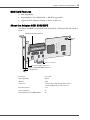
1
Adaptec SCSI Card 29320LPE
Installation and User’s Guide
●
2
Copyright
©2006 Adaptec, Inc. All rights reserved. No part of this publication may be reproduced, stored in a retrieval system, or transmitted
in any form or by any means, electronic, mechanical, photocopying, recording or otherwise, without the prior written consent of
Adaptec, Inc., 691 South Milpitas Blvd., Milpitas, CA 95035.
Trademarks
Adaptec, SCSISelect and the Adaptec logo are trademarks of Adaptec, Inc., which may be registered in some jurisdictions.
Microsoft and Windows are trademarks of Microsoft Corporation in the US and other countries, used under license.
Red Hat is a trademark of Red Hat, Inc. in the US and other countries, used under license.
Novell and NetWare are trademarks of Novell, Inc. in the US and other countries, used under license.
All other trademarks are the property of their respective owners.
Changes
The material in this document is for information only and is subject to change without notice. While reasonable efforts have been
made in the preparation of this document to assure its accuracy, Adaptec, Inc. assumes no liability resulting from errors or
omissions in this document, or from the use of the information contained herein.
Adaptec reserves the right to make changes in the product design without reservation and without notification to its users.
Disclaimer
IF THIS PRODUCT DIRECTS YOU TO COPY MATERIALS, YOU MUST HAVE PERMISSION FROM THE COPYRIGHT
OWNER OF THE MATERIALS TO AVOID VIOLATING THE LAW WHICH COULD RESULT IN DAMAGES OR OTHER
REMEDIES.
●
3
Adaptec Customer Support
If you have questions about installing or using your Adaptec product, check this document first—you will find answers to most of
your questions. If you need further assistance, use the support options listed below. To expedite your service, have your system in
front of you.
Technical Support Identification (TSID) Number
●
Before contacting Technical Support, you need your unique 12-digit TSID number. The TSID number identifies your product
and support status.
●
The TSID number is included on a white, bar-coded label, like this example:
●
Affix a copy of the TSID label to the CD jacket so that you don’t lose it.
North America
●
Visit our Web site at www.adaptec.com.
●
Search the Adaptec Support Knowledgebase (ASK) at ask.adaptec.com for articles, troubleshooting tips, and frequently asked
questions for your product.
●
For information about Adaptec’s support options, call +1 408-957-2550,
24 hours per day, 7 days per week. To speak with a Technical Support Specialist,
●
For Hardware products call +1 408-934-7274,
Monday to Friday, 5:00 A.M. to 5:00 P.M., Pacific Time.
●
For RAID and Fibre Channel products call +1 321-207-2000,
Monday to Friday, 5:00 A.M. to 5:00 P.M., Pacific Time.
●
For support via e-mail, submit your question at ask.adaptec.com.
●
You can order Adaptec products, including accessories and cables, by calling +1 408-957-7274. Or, you can order cables online at
www.adaptec.com/buy-cables.
Europe
●
Visit our Web site at www.adaptec-europe.com.
●
German: Call +49 89 43 66 55 22, Monday to Friday, 9:00 to 17:00, CET. For support via e-mail, submit your question at
ask-de.adaptec.com.
●
French: Call +49 89 43 66 55 33, Monday to Friday, 9:00 to 17:00, CET. For support via e-mail, submit your question at
ask-fr.adaptec.com.
●
English: Call +49 89 43 66 55 44, Monday to Friday, 9:00 to 17:00, GMT. For support via e-mail, submit your question at
ask.adaptec.com.
●
You can order Adaptec cables online at www.adaptec.com/buy-cables.
Japan
●
Visit our Web site at www.adaptec.co.jp.
●
Call +81-3-3831-5190.
●
4
Limited 3-Year Hardware Warranty
1. Adaptec, Inc. (“Adaptec”) warrants to the purchaser of this product that it will be free from defects in material and workmanship
for a period of three (3) years from the date of purchase. If the product should become defective within the warranty period,
Adaptec, at its option, will repair or replace the product, or refund the purchaser’s purchase price for the product, provided it is
delivered at the purchaser’s expense to an authorized Adaptec service facility or to Adaptec.
2. Repair or replacement parts or products will be furnished on an exchange basis and will either be new or reconditioned. All
replaced parts or products shall become the property of Adaptec. This warranty shall not apply if the product has been damaged
by accident, misuse, abuse or as a result of unauthorized service or parts.
3. Warranty service is available to the purchaser by delivering the product during the warranty period to an authorized Adaptec
service facility or to Adaptec and providing proof of purchase price and date. The purchaser shall bear all shipping, packing and
insurance costs and all other costs, excluding labor and parts, necessary to effectuate repair, replacement or refund under this
warranty.
4. For more information on how to obtain warranty service, write or telephone Adaptec at 691 South Milpitas Boulevard,
Milpitas, CA 95035, (800) 959-7274.
5. THIS LIMITED WARRANTY DOES NOT EXTEND TO ANY PRODUCT WHICH HAS BEEN DAMAGED AS A RESULT OF
ACCIDENT, MISUSE, ABUSE, OR AS A RESULT OF UNAUTHORIZED SERVICE OR PARTS.
6. THIS WARRANTY IS IN LIEU OF ALL OTHER EXPRESS WARRANTIES WHICH NOW OR HEREAFTER MIGHT
OTHERWISE ARISE RESPECT TO THIS PRODUCT. IMPLIED WARRANTIES, INCLUDING THOSE OF
MERCHANTABILITY, FITNESS FOR A PARTICULAR PURPOSE AND NON-INFRINGEMENT SHALL (A) HAVE NO
GREATER DURATION THAN 3 YEARS FROM THE DATE OF PURCHASE, (B) TERMINATE AUTOMATICALLY AT THE
EXPIRATION OF SUCH PERIOD AND (C) TO THE EXTENT PERMITTED BY LAW BE EXCLUDED. IN THE EVENT THIS
PRODUCT BECOMES DEFECTIVE DURING THE WARRANTY PERIOD, THE PURCHASER’S EXCLUSIVE REMEDY
SHALL BE REPAIR, REPLACEMENT OR REFUND AS PROVIDED ABOVE. INCIDENTAL OR CONSEQUENTIAL
DAMAGES, INCLUDING WITHOUT LIMITATION LOSS OF DATA, ARISING FROM BREACH OF ANY EXPRESS OR
IMPLIED WARRANTY ARE NOT THE RESPONSIBILITY OF ADAPTEC AND, TO THE EXTENT PERMITTED BY LAW,
ARE HEREBY EXCLUDED BOTH FOR PROPERTY DAMAGE, AND TO THE EXTENT NOT UNCONSCIONABLE, FOR
PERSONAL INJURY DAMAGE.
7. SOME STATES DO NOT ALLOW THE EXCLUSION OR LIMITATION OF INCIDENTAL OR CONSEQUENTIAL DAMAGES
FOR CONSUMER PRODUCTS, AND SOME STATES DO NOT ALLOW LIMITATIONS ON HOW LONG AN IMPLIED
WARRANTY LASTS, SO THE ABOVE LIMITATION OR EXCLUSIONS MAY NOT APPLY TO YOU.
8. This warranty gives you specific legal rights, and you may also have other rights which vary from state to state.
●
5
Regulatory Compliance Statements
Federal Communications Commission Radio Frequency Interference Statement
WARNING: Changes or modifications to this unit not expressly approved by the party responsible for compliance could void the user’s authority to
operate the equipment.
This equipment has been tested and found to comply with the limits for a Class B digital device, pursuant to Part 15 of the FCC rules. These limits are
designed to provide reasonable protection against harmful interference in a residential installation. This equipment generates, uses, and can radiate
radio frequency energy, and if not installed and used in accordance with the instruction manual, may cause harmful interference to radio
communications. However, there is no guarantee that interference will not occur in a particular installation. However, if this equipment does cause
interference to radio or television equipment reception, which can be determined by turning the equipment off and on, the user is encouraged to try to
correct the interference by one or more of the following measures:
■
Reorient or relocate the receiving antenna.
■
Increase the separation between equipment and receiver.
■
Connect the equipment to an outlet on a circuit different from that to which the receiver is connected.
■
Consult the dealer or an experienced radio/television technician for help.
■
Use a shielded and properly grounded I/O cable and power cable to ensure compliance of this unit to the specified limits of the rules.
This device complies with part 15 of the FCC rules. Operation is subject to the following two conditions: (1) this device may not
cause harmful interference and (2) this device must accept any interference received, including interference that may cause
undesired operation.
ASC-29320LPE
Adaptec, Inc.
Tested to Comply
With FCC Standards
FOR HOME OR OFFICE USE
European Union Compliance Statement
This Information Technology Equipment has been tested and found to comply with EMC Directive 89/336/EEC, as amended by 92/31/EEC
and 93/68/EEC, in accordance with:
●
●
EN55022 (1998+A1:2000+A2:2003) Emissions
EN55024 (1998+A1:2001+A2:2003) Immunity:
– EN61000-4-2 (1995) Electrostatic discharge: ±4 kV contact, ±8 kV air
– EN61000-4-3 (1996) Radiated immunity
– EN61000-4-4 (1995) Electrical fast transients/burst: ±1 kV AC, ±0.5 kV I/O
– EN61000-4-5 (1995) Surges ±1 kV differential mode, ±2 kV common mode
– EN61000-4-6 (1996) Conducted immunity: 3 V
– EN61000-4-11 (1994) Supply dips and variation: 30% and 100%
In addition, all equipment requiring U.L. listing has been found to comply with EMC Directive 73/23/EEC as amended by 93/68/EEC in
accordance with EN60950 with amendments A1, A2, A3, A4, A11.
Australian/New Zealand Compliance Statement
This device has been tested and found to comply with the limits for a Class B digital device, pursuant to the Australian/New Zealand standard
AS/NZS 3548 set out by the Spectrum Management Agency.
Canadian Compliance Statement
This Class B digital apparatus meets all requirements of the Canadian Interference-Causing Equipment Regulations.
Cet appareil numérique de la classe B respecte toutes les exigences du Règlement sur le matériel brouilleur du Canada.
Japanese Compliance (Voluntary Control Council Initiative)
This equipment complies to class B Information Technology equipment based on VCCI (Voluntary Control Council for Interface). This
equipment is designed for home use but it may causes radio frequency interference problem if used too near to a television or radio. Please
handle it correctly per this documentation.
Contents
1
About This Guide
What You Need to Know Before You Begin ................................................... 10
Terminology Used in this Guide ...................................................................... 10
How to Find More Information....................................................................... 10
2
Kit Contents and
System Requirements
Kit Contents ...................................................................................................... 12
System Requirements........................................................................................ 12
3
About Your SCSI CARD
SCSI Card Features ........................................................................................... 14
About the Adaptec SCSI 29320LPE ................................................................. 14
4
Understanding SCSI
What is SCSI? .................................................................................................... 16
SCSI IDs............................................................................................................. 16
Terminating the SCSI Bus ................................................................................ 16
Using SCSI Devices ........................................................................................... 17
Using SCSI Disk Drives............................................................................ 17
Using Ultra320 and Ultra160 Disk Drives .............................................. 17
Using SCSI Devices .................................................................................. 18
Combining SCSI and Non-SCSI Devices ........................................................ 18
Installing Multiple SCSI Cards......................................................................... 18
Connecting the LED Connector.............................................................. 19
Overriding SCSI Termination Settings ............................................................ 19
Connecting SCSI Devices ................................................................................. 20
Adaptec SCSI Card 29320LPE ................................................................. 20
Maximum Cable Lengths ................................................................................. 21
Contents
5
●
7
Getting Started
Ultra320 SCSI on the Adaptec 29320LPE........................................................ 23
Device Drivers ................................................................................................... 23
Selecting Cables ................................................................................................. 23
SCSI Cables............................................................................................... 23
Before You Begin............................................................................................... 24
Installing the Adaptec SCSI Card..................................................................... 24
Connecting Disk Drives.................................................................................... 24
Installing with an Operating System ................................................................ 25
Installing on an Existing Operating System..................................................... 25
Uninstalling Your Adaptec 29320LPE ............................................................. 25
Replacing a SCSI Card ...................................................................................... 25
6
Installing the Driver and an Operating System
Before You Begin............................................................................................... 28
Creating a Driver Disk ...................................................................................... 28
Installing with Windows................................................................................... 28
Installing with Red Hat Linux .......................................................................... 29
Installing with SUSE Linux............................................................................... 29
Installing with NetWare.................................................................................... 29
7
Installing the Driver on an Existing Operating System
Before You Begin............................................................................................... 32
Creating a Driver Disk ...................................................................................... 32
Installing with Windows................................................................................... 32
Installing on Red Hat or SUSE Linux .............................................................. 33
Installing on NetWare....................................................................................... 33
8
Configuring the Adaptec SCSI Card with SCSISelect
Starting SCSISelect............................................................................................ 36
Exiting SCSISelect .................................................................................... 36
Using SCSISelect Settings ................................................................................. 36
SCSI Bus Interface Options ..................................................................... 36
Changing Configuration Settings............................................................ 39
Using SCSI Disk Utilities .................................................................................. 43
Listing SCSI IDs and LUNs...................................................................... 43
A
Safety Information
Electrostatic Discharge (ESD) .......................................................................... 45
Contents
B
●
8
Technical Specifications
Environmental Specifications........................................................................... 47
DC Power Requirements .................................................................................. 47
Current Requirements ...................................................................................... 47
C
Using Advanced Configuration Parameters
Using Windows SCSI Parameters .................................................................... 49
Using Driver-specific Parameters..................................................................... 50
D
Troubleshooting
Troubleshooting Checklist ............................................................................... 53
General Troubleshooting.................................................................................. 53
Troubleshooting Windows............................................................................... 54
Troubleshooting NetWare................................................................................ 54
Error Messages .................................................................................................. 56
Common Error Messages ........................................................................ 57
Driver Error Messages.............................................................................. 57
Windows Error Messages......................................................................... 59
Glossary
Index
About This Guide
In this chapter...
1
What You Need to Know Before You Begin .......................................................................... 10
Terminology Used in this Guide............................................................................................ 10
How to Find More Information ............................................................................................ 10
This Installation and User’s Guide provides information about using your Adaptec SCSI
29320LPE and SCSI devices, troubleshooting, SCSI termination, and a basic overview of SCSI
technology. It explains how to use the built-in SCSISelect® utility if you need to view or modify
your Adaptec SCSI card settings. It also explains how to install the software device drivers for
your operating system.
Chapter 1: About This Guide
●
10
What You Need to Know Before You Begin
You should be familiar with system hardware, data storage technology, and the input/output
(I/O) technology—SCSI—used by your card.
You should also be familiar with Direct Attached Storage (DAS) and Storage Area Network
(SAN) concepts and technology.
Terminology Used in this Guide
Because you can use your SCSI card to manage data storage in a variety of configurations from
DAS to SAN, the generic term “storage space” is used to refer to the disk drives and devices
being managed with SCSISelect described in this Guide.
Many of the terms and concepts referred to in this Guide are known to computer users by
multiple names. This Guide uses these terms:
●
Card (also known as Host Bus Adapter, or board)
●
Disk drive (also known as hard disk, hard drive, or hard disk drive)
●
Device (also known as a printers, tape drives, and so on.)
How to Find More Information
You can find more information about your SCSI card and the software and utilities included
with it by referring to this document:
●
Readme.txt—Includes updated product information and known issues; located on the
SCSI Installation CD.
Kit Contents and
System Requirements
2
In this chapter...
Kit Contents............................................................................................................................ 12
System Requirements ............................................................................................................. 12
This chapter lists the contents of your SCSI card kit and the system requirements that must be
met for you to successfully install and use your SCSI card.
Chapter 2: Kit Contents and System Requirements
●
12
Kit Contents
●
Adaptec SCSI 29320LPE card with full-size bracket
●
SCSISelect Utility (Embedded in the card’s BIOS)—Used to view and modify your SCSI
card and disk drive settings
●
Installation CD
●
Drivers for the Adaptec SCSI 29320LPE
●
Product documentation for the Adaptec SCSI 29320LPE
●
Readme Files
●
1 internal 68-pin high-density LVD cable with 6 positions and terminator
●
Low-profile bracket
●
Adaptec SCSI 29320LPE Quick Start Guide (printed)
System Requirements
●
PC-compatible system with Intel Pentium, or equivalent, processor
●
A motherboard with these features:
●
●
Complies with the PCIe Local Bus Specification, Revision 1.0.
One of these operating systems:
●
Microsoft® Windows Server 2003, Windows XP
●
Red Hat® Enterprise Linux 4.0
●
SUSE Linux Enterprise Server 9.0, 10.0
Note: For the latest on Adaptec’s support of Linux, or to download driver sources, visit the
Support area of the Adaptec Web site at www.adaptec.com.
●
Novell® NetWare® 6.5
●
SCO® OpenServer® 6.0
●
UnixWare®
●
Sun® Solaris™ 10
●
At least 256 MB (or more) of RAM
●
Available compatible PCIe slot
●
40 MB of free drive space
●
16-bit SVGA color monitor with a resolution of at least 800 x 600
●
CD drive
●
SCSI interface cables
About Your SCSI CARD
In this chapter...
3
SCSI Card Features................................................................................................................. 14
About the Adaptec SCSI 29320LPE....................................................................................... 14
This chapter provides an overview of standard SCSI card features, and describes the unique
features of your SCSI card.
Chapter 3: About Your SCSI CARD
●
14
SCSI Card Features
●
PCIe compatibility
●
Programmable SCSI card BIOS ROM - 1 MB (Flash upgradeable)
●
Support for LVD (Ultra320, Ultra160, or Ultra2) SCSI devices
About the Adaptec SCSI 29320LPE
The Adaptec 29320LPE is a low-profile single channel PCIe x1 Ultra320 SCSI card with these
features:
68-pin internal LVD connector
Activity
LED
PCIe x1 connector
Termination Enable jumper J4
68-pin external LVD VHDCI connector
Mounting bracket
Form factor
Low-profile
PCI compatibility
PCIe x1
Channels
Single
Connectors
1 internal 68-pin high density LVD connector
1 external VHDCI 68-pin LVD connector
Disk drives/Devices
to 15
Active termination
Yes
Programmable SCSI card BIOS ROM
Yes
Understanding SCSI
In this chapter...
4
What is SCSI?.......................................................................................................................... 16
SCSI IDs.................................................................................................................................. 16
Terminating the SCSI Bus ...................................................................................................... 16
Using SCSI Devices ................................................................................................................ 17
Combining SCSI and Non-SCSI Devices.............................................................................. 18
Installing Multiple SCSI Cards .............................................................................................. 18
Overriding SCSI Termination Settings.................................................................................. 19
Connecting SCSI Devices....................................................................................................... 20
Maximum Cable Lengths....................................................................................................... 21
This chapter provides useful information on using the Adaptec SCSI Card and your SCSI
devices. For more information about a specific SCSI device, refer to the documentation for that
device.
Chapter 4: Understanding SCSI
●
16
What is SCSI?
SCSI (pronounced “scuzzy”) stands for Small Computer Systems Interface. SCSI is an industry
standard computer interface for connecting SCSI devices (such as a disk drive, CD-ROM drive,
or scanner) to a common SCSI bus.
A SCSI bus is an electrical pathway that consists of a SCSI card installed in a system and one or
more SCSI devices. SCSI cables are used to connect the devices to the SCSI card.
For the SCSI bus to function properly, a unique SCSI ID must be assigned to the SCSI card and
each SCSI device connected to it, and the SCSI bus must be properly terminated.
SCSI IDs
Each device attached to an Adaptec SCSI Card, as well as the Adaptec SCSI Card itself, must be
assigned a unique SCSI ID number from 0 to 15 for each of the two SCSI buses. A SCSI ID
uniquely identifies each SCSI device on the SCSI bus and determines priority when two or
more devices are trying to use the SCSI bus at the same time.
Refer to the device’s documentation to set the SCSI ID. Here are some general guidelines for
SCSI IDs:
●
For internal SCSI devices, the SCSI ID is set by configuring a jumper on the device.
●
For external SCSI devices, the SCSI ID is set with a switch on the back of the device.
●
SCSI ID numbers do not need to be sequential, as long as the Adaptec SCSI Card and each
device has a different number. For example, on each of the two SCSI buses you can have an
internal SCSI device with ID 0, and an external SCSI device with ID 6.
●
SCSI ID 7 has the highest priority on the SCSI bus. The priority of the remaining IDs are in
descending order: 6 to 0, then 15 to 8.
●
The Adaptec SCSI Card is preset to SCSI ID 7 and should not be changed. This gives the
card the highest priority on the SCSI bus.
●
Most internal SCSI disk drives come from the factory preset to SCSI ID 0.
●
If you have 8-bit (or Narrow) SCSI devices, they must use SCSI IDs 0, 1, 2, 3, 4, 5, or 6.
SCSI ID 0 is recommended for the first SCSI disk drive.
●
If you are booting your system from a SCSI disk drive connected to the Adaptec SCSI
Card, the Boot SCSI ID setting in the SCSISelect utility must correspond to the SCSI ID of
the device from which you are booting. By default, the Boot SCSI ID is set to 0. We
recommend that you do not change this setting.
●
With the SCSISelect disk utility feature, you can confirm/view which SCSI ID is assigned to
each device. See Configuring the Adaptec SCSI Card with SCSISelect on page 34.
Terminating the SCSI Bus
To ensure reliable communication on the SCSI bus, the ends of the SCSI bus must be properly
terminated. This is accomplished when the device at the end of each cable, or the end of the
cable itself, has a terminator installed (or enabled). Terminators must be removed, or
termination must be disabled, on devices between the ends of each cable.
Chapter 4: Understanding SCSI
●
17
Since the method for terminating a SCSI device can vary widely, refer to the device’s
documentation for instructions on how to enable or disable termination. Here are some
general guidelines for termination:
●
Internal Ultra320, Ultra160, and Ultra2 SCSI LVD devices come from the factory with
termination disabled and cannot be changed. Proper termination for these internal devices
is provided by the built-in terminator at the end of the 68-pin internal LVD SCSI cable.
●
Termination on SE internal SCSI devices is usually controlled by manually setting a jumper
or a switch on the device, or by physically removing or installing one or more resistor
modules on the device.
●
Termination on most external SCSI devices is controlled by installing or removing a SCSI
terminator. However, termination on some external SCSI devices is enabled or disabled by
setting a switch on the back of the SCSI device.
●
By default, termination on an Adaptec SCSI Card itself is set to Automatic (the preferred
method). We recommend that you do not change this default setting. This automatic
setting is just for the Adaptec SCSI Card itself; the card cannot change the termination
setting on a device.
●
Internal and external Ultra320, Ultra 160, and Ultra2 SCSI LVD SCSI buses must be
terminated with an LVD terminator. This is sometimes referred to as an LVD terminator or
a Multi-Mode terminator.
Using SCSI Devices
Using SCSI Disk Drives
If you connect a SCSI disk drive to an Adaptec SCSI card that was previously connected to a
different SCSI card, it is recommended that you low-level format the drive before you can use
it. Back up the data on the drive before moving the drive to the new SCSI card and before you
format the drive. (SeeUsing SCSI Disk Utilities on page 43 for information on using the
SCSISelect format utility.)
! Caution: A low-level format destroys all data on the drive. Be sure to back up the data before
performing a low-level format.
Every SCSI disk drive must be physically low-level formatted, partitioned, and logically
formatted before it can be used to store data. For instructions on how to partition and format
your SCSI disk drives, refer to your operating system documentation.
Using Ultra320 and Ultra160 Disk Drives
Adaptec recommends that you connect your LVD (Ultra 320, Ultra160, and Ultra2) SCSI
devices to one SCSI Channel (bus) and your non-LVD SCSI devices (if any) to a separate SCSI
Channel (bus). This allows the LVD SCSI devices to run at their maximum performance levels
of 320 MB/sec, 160 MB/sec. or 80 MB/sec. If you combine LVD and non-LVD SCSI devices on
the same SCSI channel, the data transfer rate of the LVD SCSI devices will drop down to nonLVD SCSI performance levels of up to 40 MB/sec.
Internal LVD SCSI devices come from the factory with termination disabled and cannot be
changed. Proper termination is provided by the terminator at the end of the internal LVD SCSI
cable.
Chapter 4: Understanding SCSI
●
18
Using SCSI Devices
If you connect SCSI devices (such as scanners, tape drives, zip drives, etc.) to your Adaptec
SCSI Card, you must install the device manufacturer’s proprietary software drivers. See your
device’s documentation for details.
Combining SCSI and Non-SCSI Devices
You can install an Adaptec SCSI Card in a system that already has a non-SCSI card, such as an
ATA, SATA, or Serial Attached SCSI (SAS) controller. However, you cannot cross-connect the
disk drives and other devices: SCSI devices must be connected to an Adaptec SCSI card, ATA
devices must be connected to the ATA controller, and so on.
When you install an Adaptec SCSI Card and SCSI disk drives in a system that boots from a
non-SCSI disk drive, the system will continue to boot from the non-SCSI disk drive unless you
change the system’s CMOS configuration. You do not need to change the configuration if you
just want to use the SCSI drives for additional file storage space.
If your system’s motherboard BIOS supports the BIOS Boot Specification (BBS) feature, you
can select a different boot device without much difficulty. (To determine if the motherboard
BIOS supports BBS, refer to the system documentation or contact your motherboard
manufacturer.)
After you install the SCSI card and SCSI devices to use different kinds of disk drives in the
same system, see the following table for recommendations.
Does computer BIOS
support BBS?
Want computer to boot
from SCSI drive?
NO
NO
No action required. SCSI drives and non-SCSI
drives can be used together.
NO
YES
Run CMOS Setup program. Change primary
disk drive setting to None or No Drives
Installed (see system documentation). You
will not be able to use the non-SCSI drive(s) at
all when you boot from the SCSI drive.
YES
NO
No action required. SCSI drives and non-SCSI
drives can be used together.
YES
YES
Run CMOS Setup program and select SCSI
drive as boot device. SCSI drives and nonSCSI drives can be used together.
Then do this:
Installing Multiple SCSI Cards
You can install multiple SCSI cards in your system; you are limited only by the available system
resources (for example, IRQ settings, I/O port addresses, BIOS addresses, and so forth).
Each SCSI card you install forms a separate SCSI bus with a different set of SCSI devices. SCSI
IDs can be reused as long as the ID is assigned to a device on a different SCSI card (for example,
each SCSI card can have a device with SCSI ID 2).
If you have two or more SCSI cards and your system boots from a SCSI disk drive, leave the
SCSI card BIOS enabled on the SCSI card to which the boot disk drive is connected. Use
SCSISelect to disable the SCSI card BIOS on the other SCSI cards.
Chapter 4: Understanding SCSI
●
19
If you have two or more SCSI cards, you can choose which SCSI card is found first by your
system by physically changing the order of the SCSI cards in the PCIe/PCI/PCI-X slots. Your
system scans the PCIe/PCI/PCI-X slots in a set order.
Connecting the LED Connector
(Optional feature) Most computers have an LED disk activity light on the front panel of the
system case. If you choose to disconnect the cable from the LED connector on the
motherboard and connect it to the LED connector on the SCSI card as shown in the figure
below, the LED on the front panel of the system will light whenever there is activity on the
SCSI bus.
Note: If you connect the LED cable to the SCSI card, the LED disk activity light will no longer
indicate disk activity on the non-SCSI disk drives.
LED Cable
from
Motherboard
2-pin
LED
Cable
LED Connector
on SCSI Card
1
1
Pin 1
Overriding SCSI Termination Settings
You use SCSISelect to control the termination of the SCSI channel on an Adaptec SCSI Card.
The default termination setting for a channel is Automatic. This setting allows the SCSI card to
adjust SCSI termination automatically, depending on which connectors have SCSI devices
attached to them.
Regardless of the SCSISelect termination setting, the SCSI card termination is always disabled
when the power is turned off. If you want SCSI card termination to be enabled when the power
is turned off, you must terminate the SCSI channel manually.
To manually terminate the channel on the Adaptec SCSI 29320LPE, place a shunt on the
Termination enable jumper.The next figure shows where the jumper is located on Adaptec
SCSI 29320LPE.
Chapter 4: Understanding SCSI
●
20
Termination Enable Jumper J4
If you manually terminate the SCSI card with jumpers, you will override the SCSISelect setting.
Making changes in SCSISelect will have no effect on termination when these jumpers are
installed.
You might want to manually terminate the SCSI card if an Adaptec SCSI Card is connected to
one or more external SCSI devices that are also connected to a SCSI card in another system.
The devices can be shared between the two computers if one SCSI card is terminated when it is
powered off, while the system with the other SCSI card is using the SCSI devices.
Connecting SCSI Devices
Here are some examples of how you can connect internal and external SCSI devices to an
Adaptec SCSI Card. Attach the first device to the end connector of the cable (furthest from the
SCSI card); attach other devices to the connectors that are closer to the SCSI card.
Adaptec SCSI Card 29320LPE
Here are some examples of how you can connect internal and external SCSI devices to the
Adaptec SCSI 29320LPE card.
Built-in Terminator on
Cable
T
Terminated Device
T
The following figure shows SCSI devices connected to the internal connector.
Built-in Terminator on Cable
T
Chapter 4: Understanding SCSI
●
21
The following figure shows SCSI devices connected to the external connector.
Terminated Device
Maximum Cable Lengths
The total length of cabling (internal and external) on the SCSI bus cannot exceed the
maximum lengths listed in the following table. The third column lists the maximum number
of SCSI devices you can connect to the SCSI card.
1
2
Maximum Devices
Supported
Maximum Cable Length
Data Transfer Rate
25 m (82.0 ft)
Ultra320 SCSI (320 MB/sec)
Ultra160 SCSI (160 MB/sec)
Ultra2 SCSI (80 MB/sec)
1
12 m (39.4 ft)
Ultra320 SCSI (320 MB/sec)1
Ultra160 SCSI (160 MB/sec)
Ultra2 SCSI (80 MB/sec)
15
3 m (9.8 ft)
Fast Wide SCSI (20 MB/sec)
15
3 m (9.8 ft)
Fast SCSI (10 MB/sec)
7
3 m (9.8 ft)
Ultra SCSI (40 MB/sec for 16-bit, 20 MB/sec for
8-bit)
4
1.5 m (4.9 ft)
Ultra SCSI (40 MB/sec for 16-bit, 20 MB/sec for
8-bit)
5-72
Mixing Fast/Ultra devices with Ultra320/Ultra160 and Ultra2 SCSI devices causes the entire SCSI bus to default to
Ultra SCSI speeds and cable length requirements.
Ultra SCSI data transfer rates do not currently support more than seven devices connected to the SCSI card due to
cable lengths.
Getting Started
In this chapter...
5
Ultra320 SCSI on the Adaptec 29320LPE ............................................................................. 23
Device Drivers ........................................................................................................................ 23
Selecting Cables ...................................................................................................................... 23
Before You Begin .................................................................................................................... 24
Installing the Adaptec SCSI Card .......................................................................................... 24
Connecting Disk Drives ......................................................................................................... 24
Installing with an Operating System ..................................................................................... 25
Installing on an Existing Operating System.......................................................................... 25
Uninstalling Your Adaptec 29320LPE ................................................................................... 25
Replacing a SCSI Card............................................................................................................ 25
This chapter provides the basic information you need to set up your SCSI card and the devices
you wish to attach. It also describes the options you have for installing your SCSI card and disk
drives, and other SCSI devices.
Note: Before you begin, familiarize yourself with your SCSI cards physical features and the devices
that it supports (see page 14).
Chapter 5: Getting Started
●
23
Ultra320 SCSI on the Adaptec 29320LPE
The Adaptec SCSI 29320LPE is a single channel SCSI card with a maximum throughput of 320
MB/sec. Ultra320 is an enhanced SCSI technology that transfers data at up to 320 MB/sec.
Ultra320 SCSI allows cable length of up to 12 meters for optimal connectivity and flexibility.
See About Your SCSI CARD on page 13 for more information.
Note: For the best data I/O performance, Adaptec recommends that you keep your Low Voltage
Differential (LVD) and non-LVD/SE devices separate. (LVD devices means Ultra320, Ultra160, and
Ultra2 SCSI devices and non-LVD are Fast SCSI or Ultra SCSI devices.)
Device Drivers
An Adaptec SCSI card comes with a set of software device drivers and other files that enable it
to communicate with your system.
For information on how to install the driver for an Adaptec SCSI card, refer to the section of
this User’s Guide that describes your specific operating system.
Selecting Cables
This section describes the cable options and requirements for your SCSI card. For information
about cable lengths, see Maximum Cable Lengths on page 21.
SCSI Cables
One six-position Ultra320 SCSI LVD cable with terminator is included in the kit.
Depending on your requirements, you may need one 68-pin VHDCI external LVD SCSI cable
(similar to the one shown below) for each external SCSI device you plan to connect.
External SCSI cable—Connects to an external SCSI
disk drive or device.
Adaptec recommends using only high-quality Ultra320-rated cables with multimode
terminators for all disk drives that share a channel with Ultra320 disk drives. Avoid poor
quality cables, as they may degrade reliability. Do not use cables not rated for Ultra320
operation.
Adaptec recommends using only Adaptec SCSI cables. For more information or to purchase
cables, visit the Adaptec Web site at www.adaptec.com.
Chapter 5: Getting Started
●
24
Before You Begin
●
Read the safety information on page 45.
●
Familiarize yourself with your SCSI card’s physical features (see page 13).
●
Ensure that you have the proper cables for your SCSI card and disk drives (see page 22).
●
If you have a low-profile computer cabinet, replace the original full-height bracket with
the low-profile bracket supplied in the SCSI card kit.
●
Handle the SCSI card by its bracket or edges only.
Installing the Adaptec SCSI Card
This section describes how to install your Adaptec SCSI card into your computer cabinet.
! Caution: Electrostatic Discharge (ESD) can damage your
SCSI card. Handle the SCSI card carefully so that you do not
expose it to static charge.
1
If you have a low-profile computer cabinet, replace the
original full-height bracket on the SCSI card with the lowprofile bracket supplied in the SCSI card kit.
2
Turn off your system and disconnect the power cord.
3
Open the cabinet, following the manufacturer’s
instructions.
4
Insert the SCSI card into an available PCIe slot (compliant
with PCIe rev. 1.0) and secure the bracket in the PCIe slot,
using the retention device (for instance, a screw or lever)
supplied with your system.
5
Install and connect any internal drives using the
appropriate cable(s), then close the computer cabinet.
Note: If you connect non-LVD/SE (Wide Ultra/Ultra) SCSI devices
to the same SCSI channel as LVD (Ultra320, Ultra160 and Ultra2)
SCSI devices, the data transfer rate for the LVD SCSI devices will
drop to non-LVD/SE performance levels. To achieve maximum
data transfer rates for the LVD SCSI devices, be sure to keep them
separate.
Connecting Disk Drives
1
Set the SCSI ID of each disk drive to a unique number between 0 and 15. The SCSI card is
set to ID 7 by default. Although not recommended, you can change the SCSI card ID by
using the SCSISelect utility (see page 34).
Note: Do not change the SCSI card ID unless absolutely necessary.
2
Install a terminator (or enable termination) on the disk drive at the end of each cable, or
the end of the cable itself.
Chapter 5: Getting Started
●
25
3
Remove any terminators (or disable termination) on disk drives between the ends of each
cable.
4
Install your SCSI disk drives. If space inside your computer cabinet is limited, connect
your disk drives to the SCSI cable before installing them. (For installation instructions,
refer to your system’s documentation.)
5
To avoid causing unstable operation, do not attach a cable to the SCSI card unless the
other end of the cable is attached to a least one disk drive.
6
Alternatively, install your disk drives, then connect them to the SCSI card.
7
When all internal disk drives have been installed and connected, close your computer
cabinet, reattach the power cord, then continue with the following section.
For more information about SCSI Devices, see Understanding SCSI on page 15.
Installing with an Operating System
1
Install and connect your SCSI card and devices (see page 24).
2
Install your operating system and the driver (see page 27).
Installing on an Existing Operating System
1
Install and connect your SCSI card and devices (see page 24).
If your SCSI card has an external connector, you can connect external disk drives as well
(or instead).
2
Install the SCSI card driver (see page 31).
Uninstalling Your Adaptec 29320LPE
To uninstall your Adaptec SCSI Card 29320LPE:
1
Turn off your system and disconnect the power cord. Open the cabinet, following the
manufacturer’s instructions. Read the safety information on page 45.
2
Remove the SCSI card from the PCIe slot. Close the computer cabinet, reattach the
system’s power cord, then power on your system.
Note: The setup of some operating systems do not delete the device driver from your system
disk; it only updates the software configuration information so that the device driver is no
longer loaded during system startup.
Replacing a SCSI Card
The task of replacing one SCSI card with another is similar to the task of adding a SCSI card.
When replacing a SCSI card, though, you add the new SCSI card before removing the old one.
Note: If you do not install the new SCSI card first, your operating system may fail to boot. If this
happens, remove the new SCSI card and reinstall the original one.
To replace a SCSI card:
1
Turn off your system and disconnect the power cord. Open the cabinet, following the
manufacturer’s instructions. Read the Safety Information on page 45.
Chapter 5: Getting Started
●
26
2
Leaving the existing SCSI card in place, install the new SCSI card, following the
instructions provided Installing the Adaptec SCSI Card on page 24.
3
Power on your system.
4
If prompted, install the operating system driver.
5
If prompted, restart your system.
6
Ensure that the new SCSI card is functioning properly, then power off your system and
disconnect the power cord. Open the cabinet, following the manufacturer’s instructions.
Read the Safety Information on page 45.
7
Disconnect any SCSI devices from the old SCSI card and transfer them to the new SCSI
card.
8
Remove the old SCSI card from its PCI, PCI-X or PCIe slot. Close the computer cabinet,
reattach the system’s power cord, then power on your system.
Installing the Driver and an Operating
System
6
In this chapter...
Before You Begin .................................................................................................................... 28
Creating a Driver Disk ........................................................................................................... 28
Installing with Windows ........................................................................................................ 28
Installing with Red Hat Linux ............................................................................................... 29
Installing with SUSE Linux.................................................................................................... 29
Installing with NetWare ......................................................................................................... 29
This chapter explains how to install your SCSI card driver and an operating system.
Note: To install the driver on an existing operating system, see page 31.
Chapter 6: Installing the Driver and an Operating System
●
28
Before You Begin
●
Install and connect your Adaptec SCSI card and internal disk drives (see page 24).
●
Create a driver disk (see the following section).
Creating a Driver Disk
Before you can apply a driver to your operating system installation, you will need to create a
driver disk. To create the driver disk:
1
Within Windows, insert the Adaptec SCSI CD, the Main Menu will open.
2
Click Create Driver Disk, from the Main Menu.
3
Select one of the operating systems from this list:
●
Windows
●
Linux
●
NetWare
4
Select the type of operating system you want to use.
5
Select the version of the operating system.
6
When prompted, insert the floppy disk, then click OK.
The system creates the driver disk.
7
Remove and label the driver disk.
8
Continue with the installation of the operating system and SCSI card driver, as described
in the remainder of this chapter.
Installing with Windows
To install the SCSI card driver while installing Windows:
1
Insert your Windows CD, then restart the system.
2
Follow the on-screen instructions to begin the Windows installation.
3
When prompted to install a third-party driver, press F6.
Note: When F6 is active, a prompt appears at the bottom of the screen for only 5 seconds. If
you miss your chance to press F6, restart your system.
4
Insert the driver disk, then wait until prompted to install the driver. Press S to specify that
the driver is on the floppy disk, then press Enter. The system reads the disk.
5
When the driver is found, press Enter. Follow the on-screen instructions to complete the
installation.
Note: Advanced users may use software parameters to alter the configuration of the Windows
device drivers supplied by Adaptec. For more information on using advanced configuration
parameters, see Using Advanced Configuration Parameters on page 48.
Chapter 6: Installing the Driver and an Operating System
●
29
Installing with Red Hat Linux
To install the SCSI card driver while installing Red Hat Linux:
Note: For the most up-to-date information on Linux support, visit www.adaptec.com.
1
Insert the first Red Hat installation CD.
2
Restart the system.
3
When the Red Hat Welcome screen appears, type linux dd at the Boot: prompt.
4
When prompted, insert the driver disk, then select OK.
5
Follow the prompts to set up the environment you want.
6
If you are installing other third-party devices, install them now. Otherwise, select Done.
7
Continue with the Linux installation, according to the Red Hat instructions.
Installing with SUSE Linux
To install the SCSI card driver while installing SUSE Linux:
Note: For the most up-to-date information on Linux support, visit www.adaptec.com.
1
Insert the first SUSE Installation CD.
2
Restart your system.
3
When the SUSE installation selection screen appears, choose the type of installation you
want, then ...
For SLES 9.0: Press the F6 key to indicate the use of a driver disk. (If F6 is not shown on the
screen, you may have an older version of SUSE; press the Alt key instead.)
For SLES 10.0: Press the F5 key and select Yes to indicate the use of a driver disk.
4
When prompted, insert the driver disk, then press any key to continue.
5
Follow the prompts to set up the environment you want.
6
If you are installing other third-party devices, install them now. Otherwise, select Back.
7
Complete the Linux installation, following the instructions included with your operating
system.
Installing with NetWare
To install the SCSI card driver while installing NetWare:
1
Restart your system, then install NetWare. (For instructions, refer to your NetWare
documentation).
2
To be able to load additional drivers later, select Manual install mode during the first part
of the installation.
3
When the Device Drivers screen displays, check the storage adapters list, then select
Modify to add another driver.
4
Select Storage Adapters, then press Enter.
Chapter 6: Installing the Driver and an Operating System
5
If necessary, press the Delete key to remove the default SCSI driver.
6
Press Insert to add another driver.
The available drivers are displayed.
7
Insert the driver floppy disk.
8
Press the Insert key, then press Enter to scan the floppy disk drive.
9
Once the driver is selected, the new Device Driver is displayed.
10 Select Return to Driver Summary, then press Enter.
11 From the lower window menu, select Continue, then press Enter.
12 Follow the instructions in the NetWare manual to complete the installation.
●
30
Installing the Driver on an Existing
Operating System
7
In this chapter...
Before You Begin .................................................................................................................... 32
Creating a Driver Disk ........................................................................................................... 32
Installing with Windows ........................................................................................................ 32
Installing on Red Hat or SUSE Linux.................................................................................... 33
Installing on NetWare ............................................................................................................ 33
This chapter explains how to install your SCSI card driver on an existing operating system.
Note: To install the driver and an operating system, see page 27.
Chapter 7: Installing the Driver on an Existing Operating System
●
32
Before You Begin
●
Install and connect your Adaptec SCSI card and internal disk drives (see page 24).
●
Create a driver disk (see the following section).
Creating a Driver Disk
Before you can apply a driver to your operating system installation, you will need to create a
driver disk. To create the driver disk:
1
Within Windows, insert the Adaptec SCSI CD, the Main Menu will open.
2
Click Create Driver Disk, from the Main Menu.
3
Select one of the operating systems from this list:
●
Windows
●
Linux
●
NetWare
4
Select the type of operating system you want to use.
5
Select the version of the operating system.
6
When prompted, insert the floppy disk, then click OK.
The system creates the driver disk.
7
Remove and label the driver disk.
8
Continue with the installation of the operating system and SCSI card driver, as described
in the remainder of this chapter.
Installing with Windows
To install the driver on Windows:
1
Start or restart Windows.
The Found New Hardware Wizard opens and searches for the driver.
2
Insert the driver disk, select Floppy drive, then click Next.
3
Click Next, then click Next again.
4
Follow the on-screen instructions to complete the driver installation.
5
Remove the driver disk and restart your system if prompted.
Note: Advanced users may use software parameters to alter the configuration of the Windows
device drivers supplied by Adaptec. For more information on using advanced configuration
parameters, see Using Advanced Configuration Parameters on page 48.
Chapter 7: Installing the Driver on an Existing Operating System
●
33
Installing on Red Hat or SUSE Linux
To install the module on Red Hat or SUSE Linux:
1
Insert and mount the SCSI Installation CD:
Red Hat: mount /dev/cdrom /mnt/cdrom
SUSE: mount /dev/cdrom /media/cdrom
2
Install the module RPM:
rpm -Uvh mount-point/xxx/yyy.rpm
where mount-point is the specific mount point on the Linux system, xxx is the driver path,
and yyy.rpm is the rpm file.
3
Reboot your system to ensure the driver loaded correctly.
4
Run fdisk, mkfs, and create mount points for any new disk drives.
Installing on NetWare
Before you begin, ensure that your NetWare operating system has been upgraded to the
minimum patch level specified by Novell. Refer to the Novell Web site for more information.
To install the driver on NetWare:
1
Start your system.
2
At the NetWare server console prompt, type load hdetect, then press Enter if it has not be
loaded automatically.
3
At the Device types menu, select Continue, then press Enter.
4
At the Device type option, select Modify, then press Enter.
5
Select Storage Adapters, then press Enter.
6
At the Additional Driver Options menu, select Modify, then press Enter.
7
At the Driver Name menu, press the Insert key.
8
Insert the driver disk, press the Insert key, then press F3.
9
At the A:\ prompt, press Enter.
The driver installs.
10 At the Additional Driver Option menu, select Return to driver summary, then press Enter.
11 At the Driver type menu, select Load on Additional Driver Options.
12 After the driver loads, select Continue.
Configuring the Adaptec SCSI Card
with SCSISelect
8
In this chapter...
Starting SCSISelect ................................................................................................................. 36
Using SCSISelect Settings ...................................................................................................... 36
Using SCSI Disk Utilities ....................................................................................................... 43
SCSISelect, which is included with the Adaptec SCSI Card, enables you to change SCSI settings
without opening the computer or handling the card. SCSISelect also enables you to low-level
format or verify the disk media of your SCSI disk drives.
Chapter 8: Configuring the Adaptec SCSI Card with SCSISelect
●
35
The following table lists the available and default settings for each SCSISelect option.
The default settings are appropriate for most systems and should not be changed. Run
SCSISelect if you need to change or view current settings, or if you need to use the SCSI disk
utilities.
SCSISelect Options
Available Settings
Default Setting
SCSI card ID
0-15
7
SCSI card Parity
Enabled
Disabled
Enabled
SCSI card Termination:
Automatic, Enabled, Disabled
Automatic
SCSI Bus Interface Definitions:
Boot Device Configuration Options—BBS Systems Only:
Select Master SCSI card
A
A
Boot Device Configuration—Non-BBS systems Only:
Select Master SCSI card
A
A
Boot SCSI ID
0-15
0
0-7
0
Sync Transfer Rate (MB/sec)
320, 160, 80.0, 66.6, 40.0, 33.3,
20.0, 10.0, ASYN
320
Packetized
Yes, No
Yes (Enabled)
QAS
Yes, No
Yes (Enabled)
Initiate Wide Negotiation
Yes, No
Yes (Enabled)
Enable Disconnection
Yes, No
Yes (Enabled)
Send Start Unit Command
Yes, No
Yes (Enabled)
BIOS Multiple LUN Support 1
Yes, No
No (Disabled)
Include in BIOS Scan 1
Yes, No
Yes (Enabled)
Reset SCSI Bus at IC Initialization
Enabled, Disabled
Enabled
Display <Ctrl> <A> Messages during BIOS
Initialization
Enabled, Disabled
Enabled
Extended INT 13 Translation for
DOS Drives > 1 GB
Enabled, Disabled
Enabled
Post Display Mode
Verbose, Silent, Diagnostic
Verbose
SCSI card INT 13 Support
Enabled
Disabled: Scan Bus Disabled: Not
Scan
Enabled
Domain Validation
Enabled, Disabled
Enabled
Support Removable Disks Under
INT 13 as Fixed Disks 2
Disabled,
Boot Only,
All Disks
Disabled
BIOS Support for Bootable CD-ROM 2
Enabled, Disabled
Enabled
1
Boot LUN Number
SCSI Device Configuration Options:
Advanced Configuration:
1
Setting is valid only if Multiple LUN Support is enabled.
2 Settings are valid only if the controller BIOS (SCSI card INT 13 Support) is enabled.
Chapter 8: Configuring the Adaptec SCSI Card with SCSISelect
●
36
Starting SCSISelect
To start SCSISelect:
1
Turn on or restart your system.
2
During the startup process, pay careful attention to the messages that appear on your
screen.
3
When the following message appears on your screen, press the Ctrl-A keys simultaneously
(this message appears for only a few seconds):
Press <Ctrl><A> for SCSISelect (TM) Utility!
4
Select SCSI Channel.
5
From the menu that appears, use the arrow keys to move the cursor to the option you want
to select, then press Enter.
Exiting SCSISelect
To exit SCSISelect:
1
Press Esc until a message prompts you to exit (if you changed any settings, you are
prompted to save the changes before you exit).
2
At the prompt, select Yes to exit, then press any key to restart the system. Any changes you
made in SCSISelect take effect after the system restarts.
Using SCSISelect Settings
To select an option, use the arrow keys to move the cursor to the option, then press Enter. In
some cases, selecting an option displays another menu. You can return to the previous menu at
any time by pressing Esc.
To restore the original SCSISelect default values, press F6 from the main SCSISelect screen.
SCSI Bus Interface Options
●
SCSI Card ID—(Default: 7) Sets the SCSI ID for the SCSI card. The Adaptec SCSI Card is
set at 7, which gives it the highest priority on the SCSI bus. Adaptec recommends that you
do not change this setting.
●
SCSI Card Parity—(Default: Enabled) SCSI cards perform parity checking to verify the
accuracy of data transfer on the SCSI bus. Most currently available SCSI devices support
parity checking. However, if a device on the SCSI bus does not support parity checking,
disable this option. This setting changes parity for the entire SCSI card and the way it looks
at each ID on that SCSI card. You cannot mix devices that do and do not support parity
checking on the same SCSI bus.
●
SCSI Card Termination—(Default: Automatic) Determines the termination setting for the
SCSI card. The default setting is Automatic, which allows the SCSI card to adjust the
termination as needed. Adaptec recommends that you do not change this setting.
Chapter 8: Configuring the Adaptec SCSI Card with SCSISelect
●
37
SCSI Device Configuration Options
SCSI Device Configuration options can be set individually for each connected SCSI device.
Note: To configure settings for a SCSI device, you must know its SCSI ID (see Using SCSI Disk
Utilities on page 43).
●
Sync Transfer Rate—(Default: 320) Determines the maximum synchronous data transfer
rate that the SCSI card supports. We recommend that you leave the maximum (default)
value of 320 MB/sec.
●
Packetized—(Default: Yes) Packetized protocol is required to operate at 320 MB/sec.
When enabled, this option is available if it is implemented in the device drivers. However,
this option is not supported by the BIOS.
●
QAS—(Default: Yes) Quick Arbitration and Selection reduces the overhead of control
release on the SCSI bus from one device to another. This improvement reduces command
overhead and maximizes bus utilization. When enabled, this option is available if it is
implemented in the device drivers. However, this option is not supported by the BIOS.
●
Initiate Wide Negotiation—(Default: Yes) Enables the SCSI card to initiate Wide
Negotiation with the SCSI target. When set to Yes, the SCSI card attempts 16-bit data
transfer (wide negotiation). When set to No, the SCSI card uses 8-bit data transfer unless
the SCSI device requests wide negotiation.
Note: Set Initiate Wide Negotiation to No if you are using an 8-bit SCSI device that hangs or
exhibits other performance problems with 16-bit data transfer rate enabled.
●
Enable Disconnection—(Default: Yes) When set to Yes, Enable Disconnection allows the
SCSI device to disconnect from the SCSI bus. When set to No, the SCSI device cannot
disconnect from the SCSI bus. Leave the setting at Yes if two or more SCSI devices are
connected to the SCSI card. When Enable Disconnection is set to No, the SCSI device
cannot disconnect from the SCSI bus, packetized transfers cannot occur, and transfer rates
are set at Ultra 160 levels.
●
Send Start Unit Command—(Default: Yes) When set to Yes, sends the Start Unit
Command to the SCSI device at bootup. This reduces the load on a system’s power supply
by allowing the SCSI card to turn on SCSI devices one-by-one when the system boots;
otherwise, all SCSI devices turn on at the same time.
Note: Check the device documentation to make sure the device supports the command. On
most devices, you must also change a switch or jumper setting on the device to enable the
device to respond to the command.
The following options have no effect if the SCSI card BIOS is disabled. (The SCSI card BIOS is
normally enabled by default.)
●
BIOS Multiple LUN Support—(Default: No) Leave this setting at No if the device does not
have multiple LUNs. When set to Yes, the SCSI card BIOS provides boot support for a SCSI
device with multiple LUNs (for example, a CD juke box device in which multiple CDs can
be accessed simultaneously).
●
Include in BIOS Scan—(Default: Yes) When set to Yes, the SCSI card BIOS controls the
SCSI device if it is an INT 13 device (such as a SCSI disk drive) without device driver
software. When set to No, the SCSI card BIOS does not control the SCSI device and device
driver software is required. The BIOS can support up to eight INT 13 devices without an
additional device driver.
Chapter 8: Configuring the Adaptec SCSI Card with SCSISelect
●
38
Advanced Configuration Options
! Caution: Do not change the Advanced Configuration Options unless absolutely necessary and
you thoroughly understand the consequences of the change.
●
Reset SCSI Bus at IC Initialization—(Default: Enabled) When set to Enabled, the BIOS
resets the SCSI bus at POST time and then waits two seconds before scanning the bus for
SCSI devices. If this option is disabled, the SCSI card BIOS does not issue a SCSI reset and
there is no two-second delay.
●
Display <Ctrl> <A> Messages during BIOS Initialization—(Default: Enabled) When set
to Enabled, the SCSI card BIOS displays the Press <Ctrl> <A> for SCSISelect (TM) Utility!
message on your screen during system bootup. If this setting is disabled, you can still
invoke the SCSISelect Utility by pressing <Ctrl> <A> after the SCSI card BIOS banner
appears.
●
Extended INT 13 Translation for DOS Drives > 1 GByte—(Default: Enabled) When set to
Enabled, provides an extended translation scheme for SCSI hard disks with capacities
greater than 1 GB. This setting is necessary only for current versions of MS-DOS; it is not
required for other operating systems, such as NetWare or UNIX.
! Caution: Changing the translation scheme destroys all data on the drive. Be sure to back
up your disk drives before changing the translation scheme.
●
Post Display Mode—(Default: Verbose) During POST, the amount of information
displayed depends on the mode. The following modes are available:
●
Verbose—The results of the SCSI bus scan are displayed, but the results of the PCIe
bus scan are not displayed.
●
Silent—Nothing is displayed about POST, not even the Adaptec banner. However,
error messages are displayed if there is a problem on the SCSI bus or SCSI devices.
! Caution: Setting this feature to Silent completely disables the messages displayed by the
Adaptec Ultra320 SCSI card during the restart of the system. You will have to remember
where in the POST cycle of the BIOS the Press Ctrl-A to enter SCSISelect message was
displayed, and press Ctrl-A at that time to get into SCSISelect. If you press Ctrl-A too early
or too late, you will not be able to enter into the card’s setup.
●
●
Diagnostic—The PCI and SCSI bus scan results are displayed separately. There is a
pause between PCI and SCSI scans.
SCSI Card INT 13 Support—(Default: Enabled) This option controls the state of the BIOS
at POST time. The following settings are available:
●
●
Enabled—Supports INT 13 for booting from a SCSI disk drive connected to the SCSI
card. If you use this option, the following options are available:
●
Extended INT 13 Translation for DOS Drives > 1 GB
●
Support Removable Disks Under INT 13 as Fixed Disks
Disabled:NOT Scan—Set to this option if all the devices on the SCSI bus (for example,
CD-ROM drives) are controlled by software drivers and do not need the BIOS, and
you do not want the BIOS to scan the SCSI bus. SCSISelect remains available if needed.
Chapter 8: Configuring the Adaptec SCSI Card with SCSISelect
●
●
39
Disabled:Scan Bus—Set to this option if all the devices on the SCSI bus (for example,
CD-ROM drives) are controlled by software drivers and you need the BIOS to scan the
SCSI bus. Allows devices to spin up according to the setting of the Send Start Unit
Command. SCSISelect remains available if needed.
The following options have no effect if the SCSI card BIOS is disabled. (The SCSI card BIOS is
normally enabled by default.)
●
Domain Validation—(Default: Enabled) Determines the optimal transfer rate for each
device on the SCSI bus and sets transfer rates accordingly. When enabled, this option is
available if it is implemented in the device drivers. However, this option is not supported
by the BIOS. If you change this setting, the change automatically applies to both SCSI
channels.
●
Support Removable Disks Under INT 13 as Fixed Disks—(Default: Disabled) Determines
which removable-media drives are supported by the SCSI card BIOS. The options are as
follows:
●
Disabled— No removable-media drives running under DOS are treated as disk drives.
Software drivers are required because the drives are not controlled by the BIOS.
! Caution: You may lose data if you remove a removable-media cartridge from a SCSI drive
controlled by the SCSI card BIOS while the drive is on. If you want to be able to remove the
media while the drive is on, install the removable-media software driver and set Support
Removable Disks Under BIOS as Fixed Disks to Disabled.
●
Boot Only—Only the removable-media drive designated as the boot device is treated
as a disk drive.
●
All Disks—All removable-media drives supported by the BIOS are treated as disk
drives. This setting has no effect on drives under NetWare because NetWare
automatically supports removable-media drives as disk drives.
Note: The Boot Only and All Disks options are available only if the SCSI card BIOS option is
enabled.
●
BIOS Support for Bootable CD-ROM—(Default: Enabled) When set to Enabled, the SCSI
card BIOS allows the system to boot from a CD-ROM drive. If booting from a disk or
other device, make sure no bootable CD is inserted, or disable this option.
Changing Configuration Settings
The factory default settings for Adaptec SCSI cards are correct for most computers. However, if
you need to change the settings for the SCSI card or a SCSI device:
1
If you have not yet installed the SCSI card and the SCSI devices, do so now. Refer to your
SCSI card Installation Guide for details.
2
Start SCSISelect. See Starting SCSISelect on page 36.
SCSISelect detects all Adaptec SCSI cards and displays the model number, channel letter,
slot number, and PCI address for each card and channel. Channels are listed separately.
3
Select the 29320LPE, then press Enter.
Chapter 8: Configuring the Adaptec SCSI Card with SCSISelect
Adaptec
SCSISelect(TM)
29320LPE
●
40
Utility v4.31.0
06:04:00
<Arrows> move cursor, <Enter> to select option, <Esc> to exit ( * =default)
4
The Options menu appears. Select Configure/View SCSI card Settings. (For details see
Using SCSI Disk Utilities on page 43.)
Adaptec
SCSISelect(TM)
29320LPE
Utility v4.31.0
06:04:00
Would you like to configure the SCSI controller, or run the SCSI
disk utilities? Select the option and press <Enter>.
Options
Configure/View SCSI Controller Settings
SCSI Disk Utilities
<Arrows> move cursor, <Enter> to select option, <Esc> to exit (*=default)
The Configuration menu appears. The Configuration menu displays the current settings
for the SCSI bus interface. The BIOS Information section at the bottom of the menu
displays the Interrupt (IRQ) channel and I/O Port Address of the selected device. This
section cannot be modified.
Note: Text displayed in yellow is for information only and cannot be selected.
From the Configuration menu, you can access the following settings:
●
Boot Device Configuration
●
SCSI Device Configuration
●
Advanced Configuration Options
Chapter 8: Configuring the Adaptec SCSI Card with SCSISelect
●
41
If you select Boot Device Configuration, the Boot Device Configuration menu appears.
The non-BBS version is shown in the next figure. This menu displays and provides menu
options for setting Master SCSI controller, Boot SCSI controller, Boot SCSI ID, and Boot
LUN Number.
Adaptec
SCSISelect(TM)
Utility v4.31.0
Boot Device Configuration
Single Image
Select Master SCSI Controller........................29320LPE, 06:04:00
Select SCSI peripheral from which to boot
Boot SCSI Controller......................................29320LPE, 06:04:00
<Arrows> move cursor, <Enter> to select option, <Esc> to exit ( * = default)
The BBS version of the Boot Device Configuration menu is shown in the next figure. This
menu displays the Select Master SCSI card option only.
SCSI Device Configuration
If you select Select Master SCSI card or Boot SCSI card (non-BBS systems only), the
Master/Boot SCSI card Selection menu appears. The asterisk indicates the default master
or boot SCSI card and channel.
Note: Default settings are always marked with an asterisk. You can press F6 to return all
settings to the defaults.
If you select SCSI Device Configuration, the SCSI Device Configuration menu appears.
This menu lists the current device settings for each SCSI ID, including IDs not assigned to
a device.
Chapter 8: Configuring the Adaptec SCSI Card with SCSISelect
●
42
H o s t A d a pSteCr In
n su ra tio n
S te
I Drfae cveic De eCfino itio
n fig
H o s t A d a p te r In te rru p t < IR Q > C h1 a1 n n e l ..............
S C S I C h a n n e l In te rfa c e D e fin itio n s
H o s t A d a p te r S C S I ID ........................................
7
S C S I P a r ity C h e c k in g ........................................
E n a b le d
H o s t A d a p te r S C S I T e rm in a tio n E........................
n a b le d
A d d itio n a l O p tio n s
S C S I D e vic e C o n fig u r a tio n ................................
P re s s < E n te r>
A d va n c e d C o n fig u r a tio n O p tio n sP.......................
re s s < E n te r>
#8
#9
#10 #11 #12 #13 #14#15
If you do not know the SCSI ID of a device you want to configure, press Esc to get back to
the Options menu. Then, select SCSI Disk Utilities. A list of SCSI devices and SCSI ID
appears. Note the ID of the device you want to configure. Press Esc to redisplay the
Options menu, select Configure/View SCSI card Settings, and then select SCSI Device
Configuration.
If you select Advanced Configuration Options, the Advanced Configuration Options
menu appears. To change a setting in the Advanced Configuration Options menu, select
the setting. From the pop-up menu that appears, select a new setting.
11
7
E n a b le d
E n a b le d
P re s s < E n te r>
P re s s < E n te r>
< F 6 > - R e s e t to H o s t A d a p te r D e fa u lts
5
When you are finished changing settings, press Esc until a message prompts you to save the
changes. To save the changes, select Yes. To abandon the changes, then select No.
6
Press Esc until prompted to exit the utility, then select Yes.
The system prompts you if a restart is needed for your new settings to take effect. (Changing
the Boot SCSI card setting or running the standalone SCSI utility forces an automatic restart.)
Otherwise, your new settings take effect immediately.
Chapter 8: Configuring the Adaptec SCSI Card with SCSISelect
●
43
Using SCSI Disk Utilities
The disk utilities provide options for:
●
Listing SCSI IDs and LUNs
●
Verifying or Formatting a disk
Listing SCSI IDs and LUNs
With SCSISelect, you can list the SCSI IDs of devices attached to the SCSI card. This enables
you to quickly verify that no devices on the SCSI bus have duplicate IDs.
To view the SCSI IDs:
1
Start SCSISelect. See Starting SCSISelect on page 36.
SCSISelect detects all Adaptec SCSI cards and displays the model number, channel letter,
slot number, and PCI address for each SCSI card and channel.
2
Select the SCSI card and channel that has the devices you want to list. The Options menu
appears.
3
Select SCSI Disk Utilities.
SCSISelect scans the SCSI bus (to determine the devices installed) and displays a list of all
SCSI IDs and the devices assigned to each ID.
If a device does not show up in SCSISelect, check these items first:
●
Is the device attached to the SCSI cable?
●
Is there power to the device?
●
Does the device have a unique SCSI ID?
If two devices are on the same ID and are on the same bus, only one device or neither
of the devices may show up. To correct this, make sure that each device has a unique
SCSI ID.
4
Use the ↑ and ↓ keys to move the cursor to a specific ID and device, then press Enter.
Chapter 8: Configuring the Adaptec SCSI Card with SCSISelect
●
44
Verifying or Formatting a Disk
SCSISelect includes a utility that enables you to format and verify disks:
●
Verify Disk Media—Allows you to scan the media of a disk drive for defects. If the utility
finds bad blocks on the media, it prompts you to reassign them so they are no longer used.
●
Format Disk—Allows you to perform a low-level format on a disk drive. A disk must be
low-level formatted before you can use the operating system’s partitioning and high-level
formatting utilities. Most SCSI disk drives are preformatted at the factory and do not need
to be formatted again. If a drive is not preformatted, you can use SCSISelect to perform a
low-level format on the drive.This operation is compatible with most SCSI disk drives.
! Caution: A low-level format destroys all data on the drive. Be sure to back up your data before
performing this operation. You cannot abort a low-level format once it is started. When a lowlevel format command is sent to the disk drive, the drive will start its format. The SCSI card will
not be in use and may appear to be hung. You must not interfere or try to stop the low-level
format as this can destroy the disk drive and render it unusable. When the drive has
completed its low-level format, it will send a command to the SCSI card and allow the user to
exit the utility.
To use SCSISelect to format or verify a disk:
1
Start SCSISelect. See Starting SCSISelect on page 36.
SCSISelect detects all Adaptec SCSI cards and displays the model number, channel letter,
slot number, and PCI address for each card and channel.
2
Select the SCSI card and channel that has the devices you want to format or verify. The
Options menu appears.
3
Select SCSI Disk Utilities. SCSISelect scans the SCSI bus and lists the SCSI IDs and
associated devices on the SCSI bus.
4
From the list of SCSI devices, select the device you want to format or verify.
5
If the device has multiple logical units, a menu of LUNs appears. Select the LUN of the unit
you want to format or verify. A small menu appears.
6
Select Verify Disk Media or Format Disk.
●
If you select Verify Disk Media, SCSISelect notifies you of bad blocks and prompts you
to reassign them. Select Yes to reassign the bad blocks or No to leave them as is. You
can press Esc at any time to abort verification.
●
If you select Format Disk, a prompt appears, asking you to confirm that you want to
format the disk. Select Yes to start formatting the disk, or No to cancel formatting.
Safety Information
A
To ensure your personal safety and the safety of your equipment:
●
Keep your work area and the system clean and clear of debris.
●
Before opening the system cabinet, unplug the power cord.
Electrostatic Discharge (ESD)
! Caution: ESD can damage electronic components when they are improperly handled, and can
result in total or intermittent failures. Always follow ESD-prevention procedures when removing
and replacing components.
To prevent ESD damage:
●
Use an ESD wrist or ankle strap and ensure that it makes skin contact. Connect the
equipment end of the strap to an unpainted metal surface on the chassis.
If a wrist strap is not available, ground yourself by touching the metal chassis before
handling the SCSI card or any other part of the system.
●
Avoid touching the SCSI card against your clothing. The wrist strap protects components
from ESD on the body only.
●
Handle the SCSI card by its bracket or edges only. Avoid touching the printed circuit board
or the connectors.
●
Put the SCSI card down only on an antistatic surface such as the bag supplied in your kit.
●
If you are returning the SCSI card to Adaptec, put it back in its antistatic bag immediately.
Technical Specifications
B
In this appendix...
Environmental Specifications................................................................................................ 47
DC Power Requirements........................................................................................................ 47
Current Requirements............................................................................................................ 47
Appendix B: Technical Specifications
Environmental Specifications
Operating temperature
0 °C to 55 ° C
Relative humidity
10% to 90% (non-condensing)
Recommended Op-Humidity
40% to 60%@ 22 °C
Altitude
3,000m operating
4,500m non-operating
Note: Forced airflow is recommended, but not required.
DC Power Requirements
Ripple and noise
50 mV peak-to-peak (max)
DC Voltage
3.3 V ± 10%, 12 V ± 10%
Current Requirements
Adaptec Model
Maximum Current (A)
Adaptec SCSI 29320LPE
1.0 A @ 3.3 VDC; .20 A @ 12.0 VDC
●
47
Using Advanced Configuration
Parameters
C
In this appendix...
Using Windows SCSI Parameters .......................................................................................... 49
Using Driver-specific Parameters .......................................................................................... 50
Advanced users may use software parameters to alter the configuration of the Windows device
drivers supplied by Adaptec. All Windows configuration information is stored in a data
structure supplied by Windows called the Registry. You can edit this information through a
tool called the Registry Editor.
! Caution: Do not edit your Registry unless it is absolutely necessary. If there is an error in your
Registry, your system may become nonfunctional.
Appendix C: Using Advanced Configuration Parameters
●
49
The following is a table of supported Windows Registry Settings.
Option Name
Default
Value
Valid
Value
/MAXTAGS=nnn
32
1-255
Specifies tagged command queue depth per
target.
/INSTR_ERRLOG_Z=nnn
32
0-127
Specifies the length of the instrumentation error
log.
MaximumSGList
65
2-255
Sets the maximum transfer size for an
individual command.
MaximumLogicalUnit
32
0-31
Limits the scan for connected devices on the
SCSI bus.
NumberOfRequests
255
16-255
Specifies the maximum number of commands
that can be delivered to an SCSI card.
Definition
Using Windows SCSI Parameters
Follow the instructions below to enter the registry values that affect how the Windows SCSI
manager interprets the generic configuration information of SCSI device drivers. Each driver
has its own key reference in the Registry. In these instructions, the Ultra320 key is used
(adpu320). All SCSI cards supported by the modified key are affected by the values you enter
here. A list of valid values follows:
Note: The following value keys are case-sensitive and must be entered exactly as shown.
●
MaximumLogicalUnit—This can limit the scan for connected devices on the SCSI bus.
Valid values are 0 to 32. If 1 is specified, the Windows SCSI manager assumes that no SCSI
targets support LUNs other than LUN 0. Otherwise, LUNs from 0 to 31 are scanned during
system initialization. The data type for this value is REG_DWORD.
●
MaximumSGList—Specifies the maximum number of Scatter/Gather elements. Valid
values are 2-255. The data type for this value is REG_DWORD.
●
NumberOfRequests—specifies the maximum number of commands that can be delivered
to an SCSI card. Valid values are 16-255. The data type for this value is REG_DWORD.
To enter Windows parameters:
1
Select Run from the Start button.
2
Type regedt32,then press Enter.
3
Open the registry list to the following location:
\HKEY_LOCAL_MACHINE\System\CurrentControlSet\Services\adpu320
\Parameters\Device
If the Parameters\Device keys already exist, skip to Step 8 below to begin entering values. If
the keys do not yet exist, you need to create them by continuing with Step 4.
4
Click the adpu320 key.
5
Select the Add Key from the Edit menu; type Parameters in the Key Name edit box. Leave
the Class edit box blank.
6
Click the Parameters key.
Appendix C: Using Advanced Configuration Parameters
7
●
50
Select the Add key from the Edit menu; type Device in the Key Name edit box. Leave the
Class edit box blank.
To specify a certain SCSI card, append Device with the number of the SCSI card. For
example, type Device0 for the first SCSI card, Device1 for the second, and so on. If you
omit the SCSI card number, the configuration information applies to all Ultra320 SCSI
cards.
8
Click the Device key.
9
Select Add Value from the Edit menu. In the Value Name edit box, enter one of the valid
parameter values. Make sure to enter the appropriate data type for the value. To enter
additional values, repeat Step 8 and Step 9.
Note: Changes made with the Registry Editor do not take effect until you shut down and then
restart your system.
Using Driver-specific Parameters
To use the Registry Editor to enter adpu320m.sys driver-specific parameters that affect the
configuration information for Adaptec SCSI PCI device drivers, follow the instructions below.
A list of valid parameters follows:
Note: The following parameters are case-sensitive and must be entered exactly as shown. When
entering multiple parameters, each parameter must be separated by a space.
●
/MAXTAGS=nnn—specifies the tagged command queue depth per target. If a number is
not specified, the tagged queue depth defaults to 32. Valid values are 1-255. The data type
for this value is REG_SZ.
●
/INSTR_ERRLOG_Z=nnn—sets the maximum number of error log entries, if /
INSTRUMENTATION is enabled. If a number is not specified, the maximum number or
error log entries defaults to 32. Valid values are 0-127. The data type for this value is
REG_SZ
To enter driver-specific parameters:
1
Select Run from the Start button.
2
Type regedt32, then press Enter.
3
Open the registry list to the following location:
\HKEY_LOCAL_MACHINE\System\CurrentControlSet\Services\adpu320
\Parameters\Device
If the Parameters\Device keys already exist, skip to Step 10 below to begin entering
parameters. If the keys do not yet exist, you need to create them by continuing with Step 4.
4
Click the adpu320 key.
5
Select the Add Key from the Edit menu; type Parameters in the Key Name edit box. Leave
the Class edit box blank.
6
Click the Parameters key.
Appendix C: Using Advanced Configuration Parameters
7
●
51
Select the Add key from the Edit menu; type Device in the Key Name edit box. Leave the
Class edit box blank.
To specify a certain SCSI card, append Device with the number of the SCSI card. For
example, type Device0 for the first SCSI card, Device1 for the second, etc. If you omit the
SCSI card number, the configuration information applies to all Ultra320 SCSI cards.
8
Click the Device key.
9
Select Add Value from the Edit menu, and type DriverParameters in the Value Name edit
box. Enter REG_SZ as the data type, then press Enter.
10 A String Editor text box appears. Enter valid parameters in the text box. When entering
multiple parameters, each parameter must be separated by a space.
Note: Changes made with the Registry Editor do not take effect until you restart your system.
Troubleshooting
D
In this chapter...
Troubleshooting Checklist ..................................................................................................... 53
General Troubleshooting ....................................................................................................... 53
Troubleshooting Windows..................................................................................................... 54
Troubleshooting NetWare...................................................................................................... 54
Error Messages........................................................................................................................ 56
This chapter provides troubleshooting information for your Adaptec SCSI card and its device
drivers.
Chapter D: Troubleshooting
●
53
Troubleshooting Checklist
Most problems with using the Adaptec SCSI Card results from errors in preparing and
connecting devices on the SCSI bus. If you have problems, check these items first:
●
Are all SCSI cables and power cables properly connected?
●
Are all SCSI devices turned on?
●
Is the Adaptec SCSI Card firmly seated and secured in the PCIe expansion slot?
●
Is the PCIe expansion slot compliant with PCIe Rev. 1.0 or higher?
●
Are all SCSI devices on each SCSI bus assigned unique SCSI IDs?
●
Is termination set correctly on all the devices?
Note: If you have problems with a specific SCSI device when other connected SCSI devices are
working correctly, please contact the manufacturer of the problem device for troubleshooting
information.
General Troubleshooting
The following procedures can be used for troubleshooting in all operating systems.
What if I can’t load the driver and suspect that it is an resource conflict?
These are some basic steps that can assist the motherboard in correctly allocating resources to
your PCI devices and/or resolve existing IRQ conflicts:
Verify that all on-board devices not being used are disabled so that the resources they are being
allocated can be freed up for allocation to another device. This is accomplished through the
motherboard CMOS/BIOS setup utility. For example, if you are not using the onboard sound
port on your motherboard, you can usually disable this chipset and free up the resource it is
currently being assigned.
What if I have devices that are showing up at the wrong speed (usually slower) when the BIOS
scans the SCSI bus during boot?
●
Make sure you are using the terminated cable supplied with your Adaptec kit.
●
Do not mix LVD and non-LVD SCSI devices on the same channel. All Ultra320, Ultra160
and Ultra2 devices need to be on a single channel. Adding a slower device will slow down
all the devices on the same bus.
●
Be sure you have the connection firmly seated. A bad connection on a disk drive or other
devices can cause problems talking to that device at the maximum speed.
●
Try to route the cable inside the system as smoothly as possible. Avoid bending, flexing, or
stretching the cable inside your system.
●
If you are not booting from the SCSI card (your boot disk drive is not attached to the card)
then the BIOS on the card should be disabled.
Chapter D: Troubleshooting
●
●
54
If the card driver will not load and you do not have your boot disk drive attached to the
card, try removing all the cables and devices from the card then boot up.
●
If this is successful and the driver loads, then you may have a problem with a device
setting (conflicting SCSI ID numbers or Termination setting) or you have a bad cable
or cable connection. Reattach devices one at a time until the problem is isolated,
remembering to follow the correct termination procedure for the SCSI bus. For more
information on termination, see Terminating the SCSI Bus on page 16.
What do I do when during boot, the Adaptec SCSI Card banner comes up but the system
hangs?
Go into SCSISelect and choose the settings for the device that are more appropriate for the
device time.
All narrow devices should have the option for Initiate Wide set to No and the Maximum
transfer rate should be set to the fastest that the device supports, usually 20 MB/sec. (check
your device documentation for this information). Setting the speed any faster for these devices
will not improve performance of the device and can make the SCSI bus unstable. This can also
be caused by incorrect termination, a resource conflict, or a bad device or cable.
Troubleshooting Windows
I made changes to the SCSI card configuration and Windows no longer boots!
The boot manager for Windows contains recovery logic to allow you to return to the last
known good configuration. If you have changed your SCSI card configuration and Windows
no longer starts:
1
Undo any hardware changes you have made to the system since it was last operational.
2
Restart the system. Watch the display carefully during startup. When you see the following
message at the bottom of the screen, press F8:
Starting Windows...
This opens the Windows Advanced Options menu. Select Last Known Good
Configuration; then select a boot profile.
3
Once your system is operational again, check all of the hardware and software
configuration changes you want to make. Look specifically for conflicts with parts of the
existing system configuration that are not being changed.
Troubleshooting NetWare
The error messages listed below are the messages associated with the NetWare driver. Messages
are listed sequentially according to the last three digits of the error code. For example,
[xxxxx080], [xxxxx081], [xxxxx082], and so on.
Note: When reporting problems to Adaptec Customer Support, be sure to include the complete
error code in your problem description.
[xxxxx080] Unable to allocate memory
This indicates that there may be a problem with the amount of memory installed in your
system. Verify that your system has at least the minimum amount of memory required by your
operating system.
Chapter D: Troubleshooting
●
55
[xxxxx081] SCSI card software initialization failure
An error has occurred while the driver was setting up its internal data structures. Verify that
your SCSI card is supported by this version of the driver.
[xxxxx082] Internal driver error
An error has occurred while the driver was setting up its internal data structures. Try installing
the most up-to-date version of the driver available from the Adaptec Web site,
www.adaptec.com.
[xxxxx083] SCSI card not supported by this version of the driver
Your SCSI card is not supported by the driver on your system. You may have installed a new
SCSI card and have not updated the driver on your system.
[xxxxx084] SCSI card software initialization failure
An error has occurred while the driver was setting up its internal data structures. Try installing
the most up-to-date version of the driver available from the Adaptec Web site,
www.adaptec.com.
[xxxxx085] Unable to allocate memory
This indicates that there may be a problem with the amount of memory installed in your
system. Verify that your system has at least the minimum amount of memory required by your
operating system.
[xxxxx087] Internal driver error
An error has occurred while the driver was setting up its internal data structures. Try installing
the most up-to-date version of the driver available from the Adaptec Web site,
www.adaptec.com.
[xxxxx088] SCSI card software initialization failure
An error has occurred while the driver was setting up its internal data structures. Try installing
the most up-to-date version of the driver available from the Adaptec Web site,
www.adaptec.com.
[xxxxx089] Unable to allocate memory
This indicates that there may be a problem with the amount of memory installed in your
system. Verify that your system has at least the minimum amount of memory required by your
operating system.
[xxxxx096] SCSI card hardware initialization failure - possible resource conflict
The driver has attempted to initialize the SCSI card, but failed. This might suggest that the
SCSI card resources (for example, IRQ) conflict with the resources of another board installed
in your system.
[xxxxx099] SCSI card software initialization failure
[xxxxx09a] SCSI card software initialization failure
[xxxxx09b] SCSI card software initialization failure
An error has occurred initializing one of the driver’s internal data structures for a device
connected to the SCSI card. This may result in problems accessing the device. Try installing the
most up-to-date version of the driver available from the Adaptec Web site, www.adaptec.com.
Chapter D: Troubleshooting
●
56
[xxxxx0ab] Driver already loaded for this SCSI card
The driver is already loaded for this SCSI card. Verify that the correct SCSI card is specified in
your command line or startup file.
[xxxxx0ac] Driver already loaded for all SCSI cards
The driver is already loaded for all the supported adapters in this system.
[xxxxx0a4] SCSI bus reset by third-party hardware
Hardware such as an array enclosure may have reset the SCSI bus. This is a normal condition
unless you receive additional errors.
[xxxxx0a7] Unable to allocate memory
[xxxxx0a8] Unable to allocate memory
This indicates that there may be a problem with the amount of memory installed in your
system. Verify that your system has at least the minimum amount of memory required by your
operating system.
[xxxxx0a9] Possible interrupt conflict
This indicates that the SCSI card IRQ conflicts with the IRQ of another board installed in your
system. Check your hardware documentation for instructions on setting and changing IRQs.
[xxxxx0c9] Invalid command line parameter
A command line option for the driver is invalid. See your operating system manual for valid
command line options.
[xxxxx0ca] Invalid command line syntax
[xxxxx0cb] Invalid command line syntax
[xxxxx0cc] Invalid command line syntax
The command line syntax for the driver is incorrect. See your operating system manual for
entering the correct syntax.
[xxxxx07c] Unable to allocate memory
[xxxxx07d] Unable to allocate memory
[xxxxx07e] Unable to allocate memory
[xxxxx07f] Unable to allocate memory
This indicates that there may be a problem with the amount of memory installed in your
system. Verify that your system has at least the minimum amount of memory required by your
operating system.
Error Messages
Error messages generated by the Windows drivers can be viewed by opening the Windows
Event Viewer error logs.
To view events generated by the driver:
1
Double-click the Event Viewer icon in the Administrative Tools program group.
Error messages generated by the driver show up as Event ID 11. Error messages generated
by the SCSI port show up as Event ID 9.
Chapter D: Troubleshooting
2
●
57
To view event details, select System Log from the Event Viewer tree. Double-click the
appropriate Windows driver event that has an Event ID of 11. (There may be none or
multiple driver events.)
The top portion of the Event Detail dialog box displays information such as the time that
the event was generated, the system on which the event occurred (in case of remote
monitoring), and the description of the event. The Data section of the Event Details dialog
box displays the error messages generated.
Click the Words option.
In the Data section of the dialog box, the entry in the second row and second column (to
the right of the 0010: entry) lists the error message generated by the driver. The common
error messages for the driver are described in Driver Error Messages below.
Note: The entry in the third row of the last column identifies the SCSI ID of the device
originating the error.
Common Error Messages
Here is what you should do if the following messages appear on the screen at bootup:
“Device connected, but not ready”
The host system received no answer when it requested data from an installed SCSI device.
Run SCSISelect and set the Send Start Unit Command to Yes for the particular SCSI device ID.
See Starting SCSISelect on page 36.
Ensure that the device is set to spin up when the power is switched on. The spin up option is
typically set by a jumper. (refer to the documentation for the device.)
“Start unit request failed”
This message can appear if the option to send Start Unit Command is set to Yes and device is
not a disk drive. If this is the case, then change the setting to No in SCSISelect for the device.
The SCSI card BIOS was unable to send a Start Unit Command to one of the installed SCSI
devices. Run SCSISelect and disable the Send Start Unit Command for the device.
“Time-out failure during...”
An unexpected time-out occurred:
●
Verify that the SCSI bus is properly terminated.
●
Verify that all cables are properly connected.
●
Try disconnecting the SCSI device cables from the SCSI card and then starting the system.
If the system successfully restarts, one of the SCSI devices may be defective.
Driver Error Messages
The following error messages are listed sequentially according to the last three digits of the
error message. For example, [xxxxx010], [xxxxx011], [xxxxx012], and so on.
Note: When reporting problems to Adaptec Customer Support, be sure to include the complete
error message in your problem description.
Chapter D: Troubleshooting
●
58
[xxxxx004] Command completed with error
[xxxxx005] Command completed with error
[xxxxx006] Command completed with error
A request issued to a target device completed with indication that there is an error. In most
cases, the error is recovered and normal operations continues.
[xxxxx010] Error issuing command
An error has occurred while the driver was setting up its internal data structures. Try installing
the most up-to-date version of the driver available from the Adaptec Web site,
www.adaptec.com.
[xxxxx011] Error issuing command
The requested command is not supported by this driver.
[xxxxx012] Error issuing command
[xxxxxx99] Error issuing command
The driver does not recognize the target device.
[xxxxx021] Target device protocol error
An unexpected event occurred during data transfer between the SCSI card and target device.
Normally, this indicates a faulty or noncompliant target device.
[xxxxx022] SCSI card or target device protocol error
The SCSI card or target device has broken the communication protocol. A badly behaving
device could cause this message to appear. Normally this is not a serious problem. If you get
this message frequently over a short period of time, it could indicate that the device or system
is malfunctioning. Unplug or turn off unused devices to see if the problem persists.
[xxxxx023] Target device parity error
The driver has detected a parity error by the target device.
[xxxxx024] Data overrun or underrun
The SCSI card was given more or less than the expected amount of data.
[xxxxx031] Target device queue full
The target device internal buffer is full.
[xxxxx032] Target device busy
The target device reports a Busy status. Another program may already be using this device.
[xxxxx050] SCSI card failure
[xxxxxx9A] SCSI card failure
Your SCSI card may not be properly installed or defective. Try resetting the SCSI card in the
PCI slot, or try installing it a different PCI slot.
Chapter D: Troubleshooting
●
59
[xxxxx081] SCSI card initialization failure
[xxxxxx8A] SCSI card initialization failure
[xxxxxx83] SCSI card initialization failure
An error has occurred while the driver was setting up its internal data structures. Verify that
your SCSI card is supported by this version of the driver.
[xxxxx089] Unable to allocate memory
This indicates that there may be a problem with the amount of memory installed in your
system. Verify that your system has at least the minimum amount of memory required by your
operating system.
[xxxxx096] SCSI card hardware initialization failure—possible resource conflict
The driver has attempted to initialize the SCSI card hardware but failed. This might suggest
that an SCSI card resource (for example, an IRQ) conflicts with another board installed in your
system.
[xxxxx097] Unable to allocate memory
This indicates that there may be a problem with the amount of memory installed in your
system. Verify that your system has at least the minimum amount of memory required by your
operating system.
[xxxxx0af] Unable to de-allocate memory that was allocated for a target device
Normally, this is not a serious problem, unless you get this message frequently over a short
period of time. The memory can be reclaimed by rebooting the system.
[xxxxx0ce] Scatter/Gather limit exceeded
An I/O request packet from the system contained a Scatter/Gather element list that contained
more elements than are supported by the miniport. Scatter/Gather is a list of data segments
that define the entire data transfer. Scatter/Gather is a means to improve total data throughput.
This error might be caused by a component external to the miniport driver, such as the
operating system or an ASPI application.
[xxxxxd4] SCSI card hardware failure - SCSI card reset
The SCSI card hardware failed and the miniport driver has to reset the hardware.
[xxxxx0d6] Internal driver error
An error has occurred while the driver was setting up its internal data structures. Try installing
the most up-to-date version of the driver available from the Adaptec Web site,
www.adaptec.com.
Windows Error Messages
Error messages generated by the Windows driver can be viewed by opening the Windows
Event Viewer error logs.
Glossary
A
active negation
Provides better noise immunity on a SCSI bus.
active termination
An active terminator uses one or more voltage regulators to produce the termination voltage, rather than
using resister voltage dividers.
asynchronous data transfer
A method of SCSI data transfer which is not synchronized to a set timing interval. Faster on short cables
than synchronous data transfer, it commonly achieves transfer rates of 2MB/s.
B
basic input/output system (bios)
A motherboard BIOS controls the basic functions of the system such as the keyboard, monitor, etc. The
BIOS on a SCSI card is used to control SCSI disk drives and perform the disk drive boot function.
bus
A pathway for data in a system.
bus mastering
The ability to process SCSI commands on the SCSI card due to its built-in processor without using the
system's CPU.
C
channel
Any path used for the transfer of data and control information between storage devices and a storage
controller or I/O SCSI card. Also refers to one SCSI bus on a disk array controller.
D
device driver
A software program stored on a PC's fixed disk and loaded into memory at boot time that enables a PC to
communicate with peripheral devices such as fixed disk drives and CD-ROM drives.
Glossary
●
61
disk drive
Physical disk drive. Randomly accessible, rewriteable data storage device. Also called hard disk, hard drive,
or hard disk drive.
E
event
Notification or alert from the system, indicating that a change has occurred.
event log
File used to maintain information about prior controller activities or errors.
I
Input/Output (I/O)
An operation, program, or device that enters data into or extracts data from a system.
L
Low Voltage Differential (LVD)
Introduced with Ultra2 SCSI, and further enhanced with Ultra160 and Ultra320 SCSI, LVD technology
enables data transfer to 320MB/s and supports cable lengths to 12 meters.
Q
Quick Arbitration Select (QAS)
An Ultra320 SCSI feature that improves the control release between SCSI devices, reducing command
overhead
S
SCSI bus
A SCSI card and one or more SCSI peripherals connected by cables in a linear chain configuration. The
SCSI card may exist anywhere on the chain, allowing connection of both internal and external SCSI
devices. A system may have more than one SCSI bus by using multiple SCSI cards.
SCSI card
An adapter card that includes all of the I/O logic, software, and processing to manage the transfer of
information between the host computer's bus and devices via a SCSI bus.
SCSI device
A device such as a SCSI card board, fixed disk drive, or CD drive that is an initiator or a target or both, and
is attached to a SCSI bus cable.
SCSI ID
A unique identification number used for each device on the SCSI chain.
Small Computer System Interface (SCSI)
The technology that connects various devices to PCs using a SCSI card that fits inside a system.
T
termination
A feature that stops the data signal at the beginning and the end of the SCSI bus. The first and last devices
on the SCSI bus must be terminated.
Glossary
●
62
throughput
A term used to describe the amount of data which can be processed by a system in a given amount of time.
W
Wide SCSI
A SCSI protocol that allows 16- and 32-bit data transfers.
Index
A
D
Adaptec SCSI 29320LPE
channels 14
connectors 14
disk drives/devices 14
features 14
form factor 14
kit contents 12
PCI compatibility 14
programmable SCSI card BIOS ROM 14
system requirements 12
termination 14
devices
combining SCSI and non-SCSI 18
using 17
disk drives
Ultra320 17
disk drives/devices
supported 14
disk media
verifying 44
domain validation 39
driver disk
creating 28
B
BIOS multiple LUN support 37
BIOS scan 37
boot device configuration 35
BBS systems only 35
non-BBS systems only 35
bus
terminating 16
C
cables
selecting 23
configuration options
SCSI devices 35
connectors
internal
external 14
creating
driver disk 28
E
electrostatic discharge 45
error messages 56
common 57
driver 57
Windows 59
existing operating system
installation 31
F
form factor 14
format disk 44
H
hard disk, hard disk drive, hard drive. See disk drives
I
installing
Index
a driver and an operating system 27
a driver disk with NetWare 29
a driver disk with Red Hat Linux 29
a driver disk with SUSE Linux 29
a driver disk with Windows 28
K
kit contents 12
L
LUNs
multiple 37
M
multiple SCSI cards 18
N
NetWare
creating a driver disk 29
non-SCSI devices 18
O
overriding
SCSI termination settings 19
P
PCI compatibility 14
PCIe slot
inserting SCSI card 24
R
Red Hat Linux
creating a driver disk 29
replacing
SCSI cards 25
S
safety
electrostatic discharge 45
SCSI
cable lengths 21
combining SCSI and non-SCSI devices 18
connecting devices 20
device configuration options 35
disk drives 17
IDs 16
installing multiple SCSI cards 18
overriding the termination settings 19
terminating the SCSI bus 16
translation for DOS drives 38
Ultra320 17
using devices 17
what is? 16
Windows driver-specific parameters 50
Windows parameters 49
SCSI bus 16
diagnostics 38
interface definitions 35
interface options 36
reset 38
scan 38
silent 38
SCSI cables
types 23
Ultra320 SCSI LVD cable 23
SCSI card 61
SCSI card BIOS
BIOS scan 37
multiple LUN support 37
SCSI card driver
installing with an operating system 27
SCSI cards
BIOS 38
changing configuration settings 39
configuring with SCSISelect 34
connecting the LED connector 19
domain validation 39
error messages 56
ID 36
installing multiple 18
maximum cable lengths 21
parity 36
removable drive support 39
replacing 25
SCSI IDs and LUNs 43
selecting cables 23
termination 36
troubleshooting 52
uninstalling 25
SCSI device
connecting 20
enable disconnection 37
initiate wide negotiation 37
packetized 37
QAS 37
send start unit command 37
sync transfer rate 37
SCSI device configuration options 35
SCSI IDs
●
64
Index
default 24
setting 24
view 43
SCSISelect 34
advanced configuration options 38
reset SCSI bus at IC initialization 38
available settings 35
boot device configuration options 35
default settings 35
exiting 36
options 35
SCSI bus interface definitions 35
settings 36
starting 36
verifying or formatting a disk 44
Small Computer Systems Interface 16
storage space 10
SUSE Linux
creating a driver disk 29
system requirements 12
T
Technical Support Identification (TSID) number 3
terminating the SCSI bus 16
termination settings
overriding 19
terminology 10
troubleshooting 52
checklist 53
general 53
NetWare 54 to 55
Windows 54
TSID Number
See Technical Support Identification Number
U
Ultra 160 17
uninstalling
Adaptec SCSI 29320LPE 25
V
verifying or formatting a disk 44
W
Windows
advanced configuration parameters 49
creating a driver disk 28
driver-specific parameters 50
error messages 59
SCSI parameters 49
supported registry settings 49
●
65
Adaptec, Inc.
691 South Milpitas Boulevard
Milpitas, CA 95035 USA
© 2006 Adaptec, Inc.
All rights reserved. Adaptec and the Adaptec logo are
trademarks of Adaptec, Inc. which may be
registered in some jurisdictions.
Part Number: CDP-00205-01-A Rev. B
JB 02/07