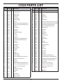
1
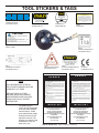
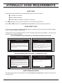
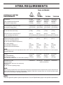
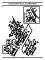
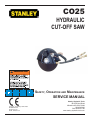
CO25
HYDRAULIC
CUT-OFF SAW
WARNING
SAFETY, OPERATION AND MAINTENANCE
SERVICE MANUAL
Copyright© The Stanley Works 2005
OPS/SVCE USA
Printed in U.S.A.
34956 8/2005 ver 2
Stanley Hydraulic Tools
3810 SE Naef Road
Milwaukie OR 97267-5698
503-659-5660
FAX 503-652-1780
www.stanley-hydraulic-tools.com
SERVICING THE STANLEY HYDRAULIC Cutoff Saw: This manual contains safety, operation, and routine
maintenance instructions. Servicing of hydraulic tools, other than routine maintenance, must be performed by an authorized and certified dealer. Please read the following warning.
WARNING
SERIOUS INJURY OR DEATH COULD RESULT FROM THE IMPROPER REPAIR OR SERVICE OF THIS TOOL.
REPAIRS AND / OR SERVICE TO THIS TOOL MUST ONLY BE
DONE BY AN AUTHORIZED AND CERTIFIED DEALER.
For the nearest authorized and certified dealer, call Stanley Hydraulic Tools at the number listed on the
back of this manual and ask for a Customer Service Representative.
TABLE OF CONTENTS
CERTIFICATE OF CONFORMITY..................................................................................................................................................4
SAFETY SYMBOLS........................................................................................................................................................................5
SAFETY PRECAUTIONS ...............................................................................................................................................................6
TOOL STICKERS & TAGS .............................................................................................................................................................8
HYDRAULIC HOSE REQUIREMENTS ..........................................................................................................................................9
HTMA REQUIREMENTS ..............................................................................................................................................................10
OPERATION ................................................................................................................................................................................. 11
PREOPERATION PROCEDURES............................................................................................................................................ 11
CHECK THE POWER SOURCE............................................................................................................................................... 11
CHECK THE TOOL ................................................................................................................................................................... 11
CHECK TRIGGER MECHANISM ............................................................................................................................................. 11
CONNECT HOSES ................................................................................................................................................................... 11
TOOL OPERATION ................................................................................................................................................................... 11
STARTUP .................................................................................................................................................................................. 11
GENERAL OPERATION ...........................................................................................................................................................12
WET CUTTING .........................................................................................................................................................................12
BROKEN CUT-OFF WHEELS ..................................................................................................................................................12
SHUTDOWN .............................................................................................................................................................................12
PERIODIC MAINTENANCE ......................................................................................................................................................13
THRUST COLLAR AND INSIDE/OUTSIDE COLLAR INSPECTION........................................................................................13
DRIVE-SHAFT SPEED CHECK................................................................................................................................................13
BEARING CHECK.....................................................................................................................................................................13
CARE AND STORAGE .............................................................................................................................................................13
CUTOFF WHEELS....................................................................................................................................................................13
TOOL.........................................................................................................................................................................................13
CUTOFF WHEEL REPLACEMENT ..........................................................................................................................................14
COLD WEATHER OPERATION ................................................................................................................................................14
EQUIPMENT PROTECTION & CARE..........................................................................................................................................15
TROUBLESHOOTING ..................................................................................................................................................................16
SPECIFICATIONS ........................................................................................................................................................................17
ACCESSORIES ............................................................................................................................................................................ 17
SERVICE ...................................................................................................................................................................................... 18
CO25 PARTS ILLUSTRATION ..................................................................................................................................................... 25
CO25 PARTS LIST ....................................................................................................................................................................... 26
WARRANTY.................................................................................................................................................................................. 27
3
CERTIFICATE OF CONFORMITY
ÜBEREINSTIMMUNGS-ZERTIFIKAT
CERTIFICAT DE CONFORMITE CEE
CERTIFICADO DE CONFORMIDAD
CERTIFICATO DI CONFORMITA
Hydraulic Tools
______________________________________________________________________
I, the undersigned:
Ich, der Unterzeichnende:
Je soussigné:
El abajo firmante:
lo sottoscritto:
Schultz, Theodore J.
Surname and First names/Familiennname und Vornamen/Nom et prénom/Nombre y apellido/Cognome e nome
hereby certify that the construction plant or equipment specified hereunder:
bestätige hiermit, daß das im folgenden genannten Werk oder Gerät:
certifies par ceci que l’ usine ou l’ équipement de construction indiqué cidessous:
por el presente certifico que la fabrica o el equipo especificado a continuacion:
certifico che l’impianto o l’attrezzatura sotto specificata:
1.
Category:
Kategorie:
Catégorie:
Categoria:
Categoria:
2.
Make/Ausführung/Marque/Marca/Marca
3.
Type/Typ/Type/Tipo/Tipo:
4.
Serial number of equipment:
Seriennummer des Geräts:
Numéro de série de l’équipement:
Numero de serie del equipo:
Matricola dell´attrezzatura:
5.
Cut-Off Saw
Stanley
CO2554101, CO2514101
All
Year of manufacture/Baujahr/année de fabrication/Año de fabricacion/Anno di fabbricazione
1998
Has been manufactured in conformity with - EEC Type examination as shown.
Wurde hergestellt in Übereinstimmung mit - EEC Typ-Prüfung nach.
Est fabriqué conformément - au(x) type(s) examiné(s) comme indiqué dans le tableau ci-après.
Ha sido fabricado de acuerdo con - tipo examen EEC como dice.
E’ stata costruita in conformitá con - le norme CEE come illustrato.
Examen CEE de type
Directive
Richtlinie
Directives particulières
Directriz
Direttiva
No.
Nr
Numéro
No
n.
Date
Datum
Date
Fecha
Data
Approved body
Prüfung durch
Organisme agréé
Aprobado
Collaudato
Date of expiry
Ablaufdatum
Date d´expiration
Fecha de caducidad
Data di scadenza
Machinery Directive
EN
EN
ISO
ISO
98/37/EC
1454
792-7
3744
8662-1
1998
1997
2001
1994
1988
Self
Self
Self
Self
Self
NA
NA
NA
NA
NA
6.
Special Provisions:
None
Spezielle Bestimmungen:
Dispositions particulières:
Provisiones especiales:
Disposizioni speciali:
Done at/Ort/Fait à/Dado en/Fatto a Stanley Hydraulic Tools, Milwaukie, Oregon USA
Date/Datum/le/Fecha/Data
3/98
Signature/Unterschrift/Signature/Firma/Firma____________________________________________________________________________
Position/Position/Fonction/Puesto/Posizione
Engineering Manager
P/N 62311 rev 02 3/05
SAFETY SYMBOLS
Safety symbols and signal words, as shown below, are used to emphasize all operator, maintenance and repair
actions which, if not strictly followed, could result in a life-threatening situation, bodily injury or damage to equipment.
This is the safety alert symbol. It is used to alert you to potential personal
injury hazards. Obey all safety messages that follow this symbol to avoid
possible injury or death.
DANGER
This safety alert and signal word indicate an imminently hazardous situation which, if not avoided, will result in death or serious injury.
WARNING
This safety alert and signal word indicate a potentially hazardous situation
which, if not avoided, could result in death or serious injury.
CAUTION
This safety alert and signal word indicate a potentially hazardous situation
which, if not avoided, may result in minor or moderate injury.
This signal word indicates a potentially hazardous situation which, if not
avoided, may result in property damage.
NOTICE
This signal word indicates a situation which, if not avoided, will result in
damage to the equipment.
IMPORTANT
This signal word indicates a situation which, if not avoided, may result in
damage to the equipment.
Always observe safety symbols. They are included for your safety and for the protection of the tool.
LOCAL SAFETY REGULATIONS
Enter any local safety regulations here. Keep these instructions in an area accessible to the operator and maintenance personnel.
5
SAFETY PRECAUTIONS
Tool operators and maintenance personnel must always comply with the
safety precautions given in this manual and on the stickers and tags attached to the tool and hose.
These safety precautions are given for your safety. Review them carefully
before operating the tool and before performing general maintenance or repairs.
Supervising personnel should develop additional precautions relating to the specific work area and local safety regulations. If so, place the added precautions in the space provided on page 5.
The CO25 Hydraulic Cut-Off Saw will provide safe and dependable service
if operated in accordance with the instructions given in this manual. Read and understand this manual and any stickers
and tags attached to the tool and hose before operation. Failure to do so could result in personal injury or equipment
damage.
• The operator must start in a work area without bystanders. Flying debris can cause serious injury.
• Do not operate the tool unless thoroughly trained or under the supervision of an instructor. Establish a training program
for all operators to ensure safe operation.
• Always wear safety equipment such as goggles, ear, breathing and head protection, and safety shoes at all times when
operating the tool. Use gloves and aprons when necessary.
• The operator must be familiar with all prohibited work areas such as excessive slopes and dangerous terrain conditions.
• Maintain proper footing and balance at all times. Alway hold the tool with both hands when the unit is running. Use a firm
grip.
• Do not inspect or clean the tool while the hydraulic power source is connected. Accidental engagement of the tool can
cause serious injury.
• Always connect hoses to the tool hose couplers before energizing the hydraulic power source. Be sure all hose connections are tight and are in good condition.
• Do not operate the tool at oil temperatures above 140°F/60°C. Operation at higher temperatures can cause higher than
normal temperatures at the tool which can result in operator discomfort.
• Do not operate a damaged, improperly adjusted, or incompletely assembled tools.
• Never wear loose clothing that can get entangled in the working parts of the tool.
• Keep all parts of your body away from the rotating parts. Long hair or loose clothing can become drawn into rotating
components.
• Always use accessories that conform to the specifications given in this manual.
• Release the trigger if the power supply has been interrupted.
• When working near electrical conductors, always assume that all conductors are energized and that insulation, clothing
and hoses can conduct electricity. Use hose labeled and certified as non-conductive.
• To avoid personal injury or equipment damage, all tool repair, maintenance and service must only be performed by authorized and properly trained personnel.
6
SAFETY PRECAUTIONS
• Never carry the tool or put it down while the wheel is rotating. Make sure it is completely stopped before moving your
position or set the tool down.
• Do not operate the tool with the wheel guard removed.
• Keep the handles dry, clean and free of oil at all times.
• Operate the tool in well ventilated areas only.
• Do not operate the tool if the wheel does not stop when the trigger is released.
• Inspect the wheel guard and collars for damage after any wheel breakage on the tool.
• Always use full throttle when cutting.
• Never cock, jam or wedge the wheel during the cut. Do not use the side of the wheen as a cutting surface.
• Make sure the tool is designed for the wheel direction suitable for the job. Do not reverse the direction of the wheel rotation by changing the direction of the oil flow.
• Always operate the tool within its rated capacity. Never exceed the maximum operating speed marked on the wheel.
• Do not operate the tool near flammable materials.
• Do not over-reach.
• Do not use the tool for applications for which it was not designed.
• Keep the wheel off all surfaces when starting the saw.
• Do not attempt to adjust the flow control on the valve handle.
• Know the location of burried or covered services before starting work.
• Adjust the wheel guard so it is between you and the cutting wheel.
• Never operate the tool when you are tired.
CUT-OFF WHEEL SAFETY
• Always inspect the cut-off wheels for possible damage before operating the tool. do not use a wheel that is cracked or
otherwise damaged.
• Never transport or store the tool with the cut-off wheel mounted on the saw.
• If the cut-off saw is dropped with a cutting wheel installed, thoroughly examine the cutting wheel before use.
• Make sure the cutting wheel is correctly mounted and tightened before use.
• Operate the cut-off saw at no load for 30 seconds in a safe position. If considerable vibration or other defects are
detected, stop operation of the tool immediately and determine the cause. Do not use the tool until the defect is corrected.
• Only use cutting wheels that comply with ANSI B7.5/ISO 525, 603.
• Check that the maximum operating speed of the cutting wheel is equal to or greater than the rated shaft speed of the
cut-off saw. Wheels must be rated at 4500 rpm minimum.
7
TOOL STICKERS & TAGS
CAUTION
Stanley Hydraulic tools
DO NOT EXCEED SPECIFIED FLOW OR PRESSURE
USE CLOSED-CENTER TOOL ON CLOSED-CENTER
SYSTEM. USE OPEN-CENTER TOOL ON OPEN-CENTER
SYSTEM. CORRECTLY CONNECT HOSES TO TOOL “IN”
AND “OUT” PORTS. IMPROPER HANDLING, USE OR OTHER
MAINTENANCE OF TOOL COULD RESULT IN A LEAK, BURST
OR OTHER TOOL FAILURE. CONTACT AT A LEAK OR BURST
CAN CAUSE OIL INJECTION INTO THE BODY. FAILURE TO
OBSERVE THESE PRECAUTIONS CAN RESULT IN SERIOUS
PERSONAL INJURY.
Model
Division of the Stanley Works
3810 SE Naef Road
Milwaukie, OR 97267
28886
COMPOSITE DECAL
(CE MODELS ONLY)
7-9 GPM / 26-34 LPM
DO NOT EXCEED 2000 PSI / 140 BAR
Stanley Hydraulic Tools
3810 SE Naef Road
Milwaukie, OR 97062
05152
ADDRESS DECAL
33206
CO25 NAME TAG
03786
GPM DECAL
CAUTION
Lwa
PROTECT YOUR EYES - WEAR SAFETY GOGGLES
1. Do not use damaged wheels.
2. Use full throttle only while cutting.
3. Use only wheels marked high speed reinforced that meet requirements
of ANSI B7.5. Wheels should be no larger than 16” diameter x 5/31” thick with a 1” arbor hole
and rated for 4700 rpm minimum speed.
4. Inspect wheel guard & collars for damage after any wheel breakage on the machine.
5. Maximum spindle speed is 4700 rpm.
113
05868
SAFETY LABEL
52539
SOUND POWER DECAL
(CE MODELS ONLY)
D
30 LPM @ 138 B AR
EHTMA CATEGORY
28811
INFORMATION PLAQUE
(CE MODELS ONLY)
11207
CIRCUIT TYPE D DECAL
(CE MODELS ONLY)
05153
STANLEY ADDRESS DECAL
(CE MODELS ONLY)
D A N G E R
NOTE
THE INFORMATION LISTED ON
THE STICKERS SHOWN, MUST BE
LEGIBLE AT ALL TIMES.
REPLACE DECALS IF THEY
BECOME WORN OR DAMAGED.
REPLACEMENTS ARE AVAILABLE
FROM YOUR LOCAL STANLEY
DISTRIBUTOR.
The safety tag (p/n
15875) at right is attached
to the tool when shipped
from the factory. Read
and understand the safety
instructions listed on this
tag before removal. We
suggest you retain this tag
and attach it to the tool
when not in use.
1. FAILURE TO USE HYDRAULIC HOSE LABELED AND CERTIFIED
AS NON-CONDUCTIVE WHEN USING HYDRAULIC TOOLS
ON OR NEAR ELECTRICAL LINES MAY RESULT IN DEATH
OR SERIOUS INJURY.
BEFORE USING HOSE LABELED AND CERTIFIED AS NONCONDUCTIVE ON OR NEAR ELECTRIC LINES BE SURE THE
HOSE IS MAINTAINED AS NON-CONDUCTIVE. THE HOSE
SHOULD BE REGULARLY TESTED FOR ELECTRIC CURRENT
LEAKAGE IN ACCORDANCE WITH YOUR SAFETY DEPARTMENT INSTRUCTIONS.
2. A HYDRAULIC LEAK OR BURST MAY CAUSE OIL INJECTION
INTO THE BODY OR CAUSE OTHER SEVERE PERSONAL
INJURY.
A
DO NOT EXCEED SPECIFIED FLOW AND PRESSURE FOR
THIS TOOL. EXCESS FLOW OR PRESSURE MAY CAUSE A
LEAK OR BURST.
B DO NOT EXCEED RATED WORKING PRESSURE OF HYDRAU
LIC HOSE USED WITH THIS
TOOL. EXCESS PRESSURE MAY
CAUSE A LEAK OR BURST.
C CHECK TOOL HOSE COUPLERS AND CONNECTORS DAILY
FOR LEAKS. DO NOT FEEL FOR LEAKS WITH YOUR
28322
CE DECAL
(CE MODELS ONLY)
D A N G E R
D DO NOT LIFT OR CARRY TOOL BY THE HOSES. DO
NOT ABUSE HOSE. DO NOT USE KINKED, TORN OR
DAMAGED HOSE.
3. MAKE SURE HYDRAULIC HOSES ARE PROPERLY CONNECTED
TO THE TOOL BEFORE PRESSURING SYSTEM. SYSTEM
PRESSURE HOSE MUST ALWAYS BE CONNECTED TO TOOL
“IN” PORT. SYSTEM RETURN HOSE MUST ALWAYS BE
CONNECTED TO TOOL “OUT” PORT. REVERSING CONNECTIONS MAY CAUSE REVERSE TOOL OPERATION WHICH CAN
RESULT IN SEVERE PERSONAL INJURY.
4. DO NOT CONNECT OPEN-CENTER TOOLS TO CLOSED-CENTER HYDRAULIC SYSTEMS. THIS MAY RESULT IN LOSS OF
OTHER HYDRAULIC FUNCTIONS POWERED BY THE SAME
SYSTEM AND/OR SEVERE PERSONAL INJURY.
5. BYSTANDERS MAY BE INJURED IN YOUR WORK AREA. KEEP
BYSTANDERS CLEAR OF YOUR WORK AREA.
6. WEAR HEARING, EYE, FOOT, HAND AND HEAD PROTECTION.
7. TO AVOID PERSONAL INJURY OR EQUIPMENT DAMAGE, ALL
TOOL REPAIR MAINTENANCE AND SERVICE MUST ONLY BE
PERFORMED BY AUTHORIZED AND PROPERLY TRAINED
PERSONNEL.
IMPORTANT
IMPORTANT
READ OPERATION MANUAL AND
SAFETY INSTRUCTIONS FOR THIS
TOOL BEFORE USING IT.
READ OPERATION MANUAL AND
SAFETY INSTRUCTIONS FOR THIS
TOOL BEFORE USING IT.
USE ONLY PARTS AND REPAIR
PROCEDURES APPROVED BY
STANLEY AND DESCRIBED IN THE OPERATION MANUAL.
USE ONLY PARTS AND REPAIR
PROCEDURES APPROVED BY
STANLEY AND DESCRIBED IN THE OPERATION MANUAL.
TAG TO BE REMOVED ONLY BY
TOOL OPERATOR.
TAG TO BE REMOVED ONLY BY
TOOL OPERATOR.
SEE OTHER SIDE
SEE OTHER SIDE
SAFETY TAG P/N 15875
8
(shown smaller then actual size)
HYDRAULIC HOSE REQUIREMENTS
HOSE TYPES
Hydraulic hose types authorized for use with Stanley Hydraulic Tools are as follows:
Certified non-conductive
Wire-braided (conductive)
Fabric-braided (not certified or labeled non-conductive)
Hose listed above is the only hose authorized for use near electrical conductors.
Hoses and listed above are conductive and must never be used near electrical conductors.
HOSE SAFETY TAGS
To help ensure your safety, the following DANGER tags are attached to all hose purchased from Stanley Hydraulic Tools. DO NOT REMOVE THESE TAGS.
If the information on a tag is illegible because of wear or damage, replace the tag immediately. A new tag may be
obtained from your Stanley Distributor.
D A N G E R
D A N G E R
1 FAILURE TO USE HYDRAULIC HOSE LABELED AND CERTIFIED AS NON-CONDUCTIVE
WHEN USING HYDRAULIC TOOLS ON OR NEAR ELECTRIC LINES MAYRESULT IN DEATH
OR SERIOUS INJURY.
FOR PROPER AND SAFE OPERATION MAKE SURE THAT YOU HAVE BEEN PROPERLY
TRAINED IN CORRECT PROCEDURES REQUIRED FOR WORK ON OR AROUND
ELECTRIC LINES.
3. DO NOT EXCEED HOSE WORKING PRESSURE OR ABUSE HOSE. IMPROPER USE OR
HANDLING OF HOSE COULD RESULT IN BURST OR OTHER HOSE FAILURE. KEEP
HOSE AS FAR AWAY AS POSSIBLE FROM BODY AND DO NOT PERMIT DIRECT CONTACT
DURING USE. CONTACT AT THE BURST CAN CAUSE BODILY INJECTION AND SEVERE
PERSONAL INJURY.
4. HANDLE AND ROUTE HOSE CAREFULLY TO AVOID KINKING, ABRASION, CUTTING, OR
CONTACT WITH HIGH TEMPERATURE SURFACES. DO NOT USE IF KINKED. DO NOT USE
HOSE TO PULL OR LIFT TOOLS, POWER UNITS, ETC.
2. BEFORE USING HYDRAULIC HOSE LABELED AND CERTIFIED AS NON-CONDUCTIVE ON
OR NEAR ELECTRIC LINES. WIPE THE ENTIRE LENGTH OF THE HOSE AND FITTING
WITH A CLEAN DRY ABSORBENT CLOTH TO REMOVE DIRT AND MOSISTURE AND TEST
HOSE FOR MAXIMUM ALLOWABLE CURRENT LEAKAGE IN ACCORDANCE WITH SAFETY
DEPARTMENT INSTRUCTIONS.
5. CHECK ENTIRE HOSE FOR CUTS CRACKS LEAKS ABRASIONS, BULGES, OR DAMAGE TO
COUPLINGS IF ANY OF THESE CONDITIONS EXIST, REPLACE THE HOSE IMMEDIATELY.
NEVER USE TAPE OR ANY DEVICE TO ATTEMPT TO MEND THE HOSE.
6. AFTER EACH USE STORE IN A CLEAN DRY AREA.
SIDE 1
3
DO NOT REMOVE THIS TAG
DO NOT REMOVE THIS TAG
THE TAG SHOWN BELOW IS ATTACHED TO “CERTIFIED NON-CONDUCTIVE” HOSE
SIDE 2
(shown smaller than actual size)
D A N G E R
D A N G E R
1 DO NOT USE THIS HYDRAULIC HOSE ON OR NEAR ELECTRIC LINES. THIS HOSE IS
NOT LABELED OR CERTIFIED AS NON-CONDUCTIVE. USING THIS HOSE ON OR NEAR
ELECTRICAL LINES MAY RESULT IN DEATH OR SERIOUS INJURY.
5. CHECK ENTIRE HOSE FOR CUTS CRACKS LEAKS ABRASIONS, BULGES, OR DAMAGE TO
COUPLINGS IF ANY OF THESE CONDITIONS EXIST, REPLACE THE HOSE IMMEDIATELY.
NEVER USE TAPE OR ANY DEVICE TO ATTEMPT TO MEND THE HOSE.
2. FOR PROPER AND SAFE OPERATION MAKE SURE THAT YOU HAVE BEEN PROPERLY
TRAINED IN CORRECT PROCEDURES REQUIRED FOR WORK ON OR AROUND
ELECTRIC LINES.
6. AFTER EACH USE STORE IN A CLEAN DRY AREA.
3. DO NOT EXCEED HOSE WORKING PRESSURE OR ABUSE HOSE. IMPROPER USE OR
HANDLING OF HOSE COULD RESULT IN BURST OR OTHER HOSE FAILURE. KEEP
HOSE AS FAR AWAY AS POSSIBLE FROM BODY AND DO NOT PERMIT DIRECT CONTACT
DURING USE. CONTACT AT THE BURST CAN CAUSE BODILY INJECTION AND SEVERE
PERSONAL INJURY.
4. HANDLE AND ROUTE HOSE CAREFULLY TO AVOID KINKING, CUTTING, OR CONTACT
WITH HIGH TEMPERATURE SURFACES. DO NOT USE IF KINKED. DO NOT USE HOSE TO
PULL OR LIFT TOOLS, POWER UNITS, ETC.
DO NOT REMOVE THIS TAG
DO NOT REMOVE THIS TAG
THE TAG SHOWN BELOW IS ATTACHED TO “CONDUCTIVE” HOSE.
SEE OTHER SIDE
SIDE 1
SIDE 2
(shown smaller than actual size)
HOSE PRESSURE RATING
The rated working pressure of the hydraulic hose must be equal to or higher than the relief valve setting on the
hydraulic system.
9
HTMA REQUIREMENTS
TOOL CATEGORY
HYDRAULIC SYSTEM
REQUIREMENTS
FLOW RATE
TYPE 1
TYPEII
7-9 gpm
(26-34 lpm)
2000 psi
(138 bar)
TYPEIII
TOOL OPERATING PRESSURE
(at the power supply outlet)
4-6 gpm
(15-23 lpm)
2000 psi
(138 bar)
SYSTEM RELIEF VALVE SETTING
(at the power supply outlet)
2100-2250 psi 2100-2250 psi 2100-2250 psi 2200-2300 psi
(145-155 bar) (145-155 bar) (145-155 bar) (152-159 bar)
MAXIMUM BACK PRESSURE
(at tool end of the return hose)
250 psi
(17 bar)
Measured at a max. fluid viscosity of:
(at min. operating temperature)
400 ssu*
400 ssu*
400 ssu*
400 ssu*
(82 centistokes) (82 centistokes) (82 centistokes) (82 centistokes)
TEMPERATURE
Sufficient heat rejection capacity
to limit max. fluid temperature to:
(at max. expected ambient temperature)
140° F
(60° C)
140° F
(60° C)
140° F
(60° C)
140° F
(60° C)
Min. cooling capacity
at a temperature difference of
between ambient and fluid temps
3 hp
(2.24 kW)
40° F
(22° C)
5 hp
(3.73 kW)
40° F
(22° C)
7 hp
(4.47 kW)
40° F
(22° C)
6 hp
(5.22 kW)
40° F
(22° C)
250 psi
(17 bar)
11-13 gpm
(42-49 lpm)
2000 psi
(138 bar)
TYPE RR
250 psi
(17 bar)
9-10.5 gpm
(34-40 lpm)
2000 psi
(138 bar)
250 psi
(17 bar)
NOTE:
Do not operate the tool at oil temperatures above 140° F (60° C). Operation at higher temperatures can cause operator
discomfort at the tool.
FILTER
25 microns
Min. full-flow filtration
30 gpm
Sized for flow of at least:
(114 lpm)
(For cold temp. startup and max. dirt-holding capacity)
25 microns
30 gpm
(114 lpm)
HYDRAULIC FLUID
Petroleum based
(premium grade, anti-wear, non-conductive)
VISCOSITY
(at min. and max. operating temps)
100-400 ssu* 100-400 ssu*
(20-82 centistokes)
100-400 ssu*
25 microns
30 gpm
(114 lpm)
25 microns
30 gpm
(114 lpm)
100-400 ssu*
NOTE:
When choosing hydraulic fluid, the expected oil temperature extremes that will be experienced in service determine the
most suitable temperature viscosity characteristics. Hydraulic fluids with a viscosity index over 140 will meet the requirements over a wide range of operating temperatures.
*SSU = Saybolt Seconds Universal
NOTE:
These are general hydraulic system requirements. See tool Specification page for tool specific requirements.
10
OPERATION
PREOPERATION PROCEDURES
CHECK THE POWER SOURCE
Careful inspection of the tool and hydraulic system before
startup is important for safe, reliable operation of the tool.
1. Using a calibrated flowmeter and pressure gauge, check
that the hydraulic power source develops a flow of 7–9 gpm
(26–34 lpm) at 2000 psi (140 bar).
2. Make certain the hydraulic power source is equipped
with a relief valve set to open at 2100–2250 psi (145–155
bar).
CHECK THE TOOL
The following items should be checked daily.
Make sure the hydraulic system control valve is in the
“OFF” position and the hoses are disconnected before
inspecting the cutoff saw.
1. Inspect the cut-off wheel and guard. Make sure the correct cut-off wheel is installed for the job. If not, follow the
instructions for Cut-off Wheel Replacement section of this
manual.
2. Inspect the wheel for chips, cracks, or other damage. For
maximum tool performance, replace the wheel if it is worn
or defective.
3. Inspect the wheel guard for cracks or other structural
damage.
4. There should be no signs of leaks.
5. Inspect the handlebar. Make sure the handlebar is securely fastened to the cutoff saw and is clean of any oil to
ensure a firm grip.
IMPORTANT
Check the speed of the motor output shaft after every
100 hours of operation.
3. Check that the safety catch on the handle assembly is
operating properly. It should prevent engagement of the
trigger unless the catch is pressed down fully in the handle
slot.
CONNECT HOSES
1. Wipe all hose couplers with a clean, lint-free cloth before
making connections.
2. Connect hoses from the hydraulic power source to the
tool fittings or quick disconnects. It is good practice to connect the return hose first and disconnect it last to minimize
or eliminate trapped pressure within the wrench.
3. Observe the flow indicators stamped on the valve handle
assembly and the hose couplers to ensure that the flow is
in the proper directions. The female couple on the tools “IN”
port is the inlet (pressure) coupler.
Note:
If the uncoupled hoses are left in the sun, pressure
increase within the hoses can make them difficult to
connect. Whenever possible, connect the free ends of
hoses together.
TOOL OPERATION
STARTUP
1. Move the hydraulic system control valve to the “ON”
position.
2. At the beginning of each shift, or after a new wheel is
installed, run the cut-off saw at operating speed for at least
one minute before starting work.
HANDHELD CONFIGURATION:
1.Press the safety catch into the handle, then slowly
squeeze the trigger.
2. Run the saw at least one minute.
3. Release the trigger and safety catch.
MOUNTED CONFIGURATION (SAW CART):
CHECK TRIGGER MECHANISM
1. Inspect the trigger and safety catch. Make sure the trigger operates smoothly and is free to travel between the
“ON: and “OFF” positions.
2. Make sure the trigger is set to disengage the cut-off saw
when released.
1. Make sure the lower edge of the cutoff wheel is at least 1
inch above the work surface.
2. Slowly squeeze the hand control lever.
3. Run the saw at least one minute, then release the control
lever.
11
OPERATION
If excessive vibration or any other defect is detected, stop
the tool immediately and determine the cause. Do not use
the tool until the problem is corrected.
Periodically look at the depth gauge and pointer to check
the actual depth of the cutting blade.
GENERAL OPERATION
6. Move slowly and safely forward along the cutting line
until the desired cut is complete. The safe forward rate
depends on your blade type.
HANDHELD CONFIGURATION:
1. Whenever possible, clamp or hold down the work and
support it securely on both sides of the cut.
2. Press the safety catch into the handle, then slowly
squeeze the trigger.
3. Start the cut with the wheel rotating. Start the work gently
with consistent pressure. Do not bump the saw into the
workpiece.
4. Feed the wheel through the material as fast as possible
without slowing the wheel rotation speed.
7. Release the hand control lever.
8. To raise the blade from of the cutting surface, wait until
the blade comes to a complete stop in the work material.
Turn the depth-control crank clockwise (CW) until the blade
clears the surface.
WET CUTTING
1. Make sure the cutting wheel is suitable for wet cutting.
2. When shutting down a wet-cutting operation:
Cutting through the material too slowly causes heat expansion and can result in wheel “pinching” in the material. This
is one of the most common causes or wheel breakage.
a. Stop the tool.
b. Shut off the water.
MOUNTED CONFIGURATION (SAW CART):
When the cutoff saw is mounted on a saw cart, always use
a motor-type hydraulic system control valve to turn the saw
“ON” and “OFF”. All ports must be connected to the tank
(hydraulic system reservoir) when the control valve is in
neutral. Alternatively, use a direct line from the tool outlet to
the tank.
IMPORTANT
Keep all four wheels of the cart on the cutting surface
at all times. Do not tip the front of the cart up during
operation or while the blade is in motion.
1. Align the cut line indicator on the line to be cut.
2. Lower the blade to approximately 1/2 to 1-inch above the
cutting surface. Set the depth gauge to ensure accurate
cutting depth.
3. Make sure the water hose and its connections are secure and there is a steady flow of coolant water.
4. Slowly squeeze the hand control lever.
5. Slowly and safely lower the rotating blade into the cutting
surface to the desired depth:
Restart the tool and allow the wheel to spin off the excess
water.
BROKEN CUT-OFF WHEELS
Cut-off wheels designed for use with portable saws are
extremely tough. When used as directed, they are difficult
to break during normal use.
If a wheel breaks while operating the cut-off saw, investigate the cause of the failure and correct the problem as
soon as possible. If you cannot determine the cause of
failure, contact the wheel manufacturer.
SHUTDOWN
1. Move the hydraulic system control valve to the “OFF”
position.
2. Disconnect the hydraulic hoses from the tool (first the
input (supply) hose, then the output (return) hose).
3. Place dust plugs in the hose ends, couplers or tool ports,
as applicable.
4. Wipe the tool thoroughly with a clean dry cloth.
5. Clean any foreign matter from the cut-off wheel surfaces.
Increase the depth by turning the depth-control crank counterclockwise (CCW).
12
OPERATION
CARE AND STORAGE
PERIODIC MAINTENANCE
For maximum performance and reliability of the tool, periodically check the following components.
Remove the cutoff wheel from the tool after use. Do not
store or transport the saw with the wheel installed. Clean
and inspect the wheel and tool before storing.
THRUST COLLAR AND INSIDE/OUTSIDE
COLLAR INSPECTION
CUTOFF WHEELS
Periodically inspect the thrust collar for damage when you
remove the cut-off wheel (refer to Cutoff Wheel Replacement).
1. Remove the key and thrust collar from the motor shaft.
2. Check the thrust collar for burrs. Remove burrs as required.
3. Check the threads on the clamping setscrew.
4. Inspect the collar bores and flanges.
5. Check for burrs. Remove burrs as required.
6. Check that the bearing surfaces are flat and run true
when mounted on the motor shaft and thrust collar.
All abrasive cutoff wheels are breakable. Exercise care in
handling and storage to prevent damage.
1. Clean used wheels to remove any dirt, debris, or grease.
Dry thoroughly.
2. Inspect the wheel for chips, cracks, or other damage. For
maximum tool performance, replace the wheel if it is worn
or defective.
3. Store cutoff wheels on a flat surface of steel or similar
rigid material.
4. If wheels are supplied with blotters attached, insert suitable separators between each wheel and the supporting
surface to preserve flatness.
DRIVE-SHAFT SPEED CHECK
5. Do not store wheels where they will be exposed to high
humidity, water or other liquids, excessive heat, or freezing
temperatures.
Check the speed of the motor output shaft at least every
100 hours of operation. The test should be performed only
by a trained, experienced technician.
6. Avoid temperatures low enough to cause condensation
on the wheels if they are moved from storage to an area of
higher temperature.
• Maintain a record of the speed checks.
7. Wheels carried on emergency vehicles should be removed after use, and discarded or stored carefully (steps 1
and 2).
• The maximum rated speed of the CO25 Hydraulic Cutoff
Saw is 4500 rpm.
TOOL
• The rated speed of the cutting wheel must be equal to,
or greater than that of the tool to ensure the integrity of the
wheel at maximum tool speed.
• Use the hydraulic power supply normally used with the
cutoff saw when conducting this test.
• Excessive speed may be caused by excessive hydraulic
fluid flow to the tool.
1. Clean the tool to remove any dirt, debris, or grease. Dry
with compressed air or clean dry cloths.
2. Replace any damaged or missing safety labels and tags
before storing the tool. Otherwise, the tool might be improperly used by someone who is not familiar with the safety
requirements.
3. Store the tool in a clean, dry place.
BEARING CHECK
Periodically inspect the bearings and associated parts for
proper operation. A worn or damaged bearing can cause
motor damage.
13
OPERATION
CUTOFF WHEEL REPLACEMENT
1. Move the hydraulic system control valve to the Off position.
2. Disconnect the hydraulic hoses from the tool (first the
input (supply) hose, then the output (return) hose).
3. Install the inside collar and blotter, rotate the collar to
align the slot in the collar with the pin on the thrust collar.
4. The maximum rated speed of the hydraulic cutoff saw
is 4500 rpm. Never install a cutoff wheel that is not rated
equal to or greater than that of the tool to ensure the integrity of the wheel at the maximum tool speed.
5. Prior to installing the wheel, inspect it for chips, cracks or
other damage and replace if damaged.
6. Install the outside blotter and collar, rotate the collar so
that the flat on the motor shaft aligns with the flat on the
outside collar.
7. Install the wheel nut using a wrench while gripping the
cutoff wheel. Tighten securely.
COLD WEATHER OPERATION
Before using the tool in cold weather, preheat the hydraulic
fluid with the power unit operating at a low speed. The oil
should be at or above 50°F (10°C) with a viscosity of 400
SSU (82 cs) before operating the tool.
14
EQUIPMENT PROTECTION & CARE
NOTICE
In addition to the Safety
Precautions in this manual,
observe the following for
equipment protection and
care.
• Make sure all couplers are wiped clean before connection.
• The hydraulic circuit control valve must be in the “OFF” position when coupling or uncoupling
hydraulic tools. Failure to do so may result in damage to the quick couplers and cause overheating
of the hydraulic system.
• Always store the tool in a clean dry space, safe from damage or pilferage.
• Make sure the circuit PRESSURE hose (with male quick disconnect) is connected to the “IN” port.
The circuit RETURN hose (with female quick disconnect) is connected to the opposite port. Do not
reverse circuit flow. This can cause damage to internal seals.
• Always replace hoses, couplings and other parts with replacement parts recommended by Stanley
Hydraulic Tools. Supply hoses must have a minimum working pressure rating of 2500 psi/172 bar.
• Do not exceed the rated flow (see Specifications) in this manual for correct flow rate and
model number. Rapid failure of the internal seals may result.
• Always keep critical tool markings, such as warning stickers and tags legible.
• Tool repair should be performed by experienced personnel only.
• Make certain that the recommended relief valves are installed in the pressure side of the system.
• Do not use the tool for applications for which it was not intended.
15
TROUBLESHOOTING
If symptoms of poor performance develop, the following chart can be used as a guide to correct the problem. When diagnosing faults in operation of the wrench, always check that the hydraulic power source is supplying the correct hydraulic
flow and pressure to the tool as listed in the following table. Use a flow meter known to be accurate. Check the flow with
the hydraulic fluid temperature at least 80o F/27o C.
PROBLEM
Tool does not operate.
Tool operates in reverse.
Oil leakage between motor housing
and ON/OFF vlave block or motor.
Trigger difficult to operate.
Saw cuts too slowly.
CAUSE
SOLUTION
Hydraulic ontrol valve OFF.
Turn the hydraulic system control
valve ON.
Hydraulic hoses not connected properly.
Make sure the hoses are connected
and the couplers are tight.
Hydraulic system not functioning.
Check power unit for correct flow and
presssure.
Couplers or hoses blocked.
Remove obstruction.
Mechanical failure.
Disassemble tool and inspect for damage.
Hoses connected to wrong ports on
tool.
Connect input (supply) line to IN port
and connect output (return) line to
OUT port.
Oil tube o-ring failure.
Replace o-ring.
Motor face seal failure.
Replace seal.
Hoses connected to wrong ports on
tool.
Connect input (supply) line to IN port
and connect output (return) line to
OUT port.
Excessive back-pressure.
If back pressure is greater than 250
psi/17 bar, correct the return line obstruction or restriction.
Wrong cut-off wheel for work material.
Use correct wheel.
Insufficient oil flow.
Adjust oil flow to 7-9 gpm/26-34 lpm.
Relief valve setting too low.
Adjust relief valve to 2100-2250
psi/145-155 bar.
16
SPECIFICATIONS
Wheel Capacity .............................................................................................................................................14-inch/15.6 cm
Weight ................................................................................................................................................................... 20 lbs/9 kg
Overall Length ..................................................................................................................................................21-inch/53 cm
Width ................................................................................................................................................................ 11-inch/28 cm
Pressure Range .......................................................................................................................... 1500-2000 psi/105-140 bar
Flow Range .............................................................................................................................................. 7-9 gpm/26-34 lpm
Optimum Flow ...................................................................................................................................................8 gpm/30 lpm
System Type ............................................................................................................................... Open Center, HTMA Type II
Porting ..............................................................................................................................................................8 SAE O-Ring
Connect Size and Type ............................................................................................................... 3/8-inch Male Pipe Adapter
Rotation RPM ................................................................................................................................................................. 4500
SOUND POWER AND VIBRATION DECLARATION
Measured A-weighted sound power level, Lwa (ref. 1pW) in decibels
Uncertainty, Kwa, in decibels
109.4 dBA
3 dBA
Measured A-weighted sound pressure level, Lpa (ref. 20 µPa) at operator’s position, in decibels
101.5 dBA
Uncertainty, Kpa, in decibels
3 dBA
Values determined according to noise test code given in ISO 15744, using the basic standard ISO3744
NOTE- The sum of a measured noise emision value and its associated uncertainty represents an upper
boundry of the range of values which is likely to occur in measurements.
Declared vibration emission value in accordance with EN 12096
Measured vibration emmission value: a
Uncertainty: K
Values determined according to ISO 8662-1, ISO 5349-1,2
5.9 m/sec²
1.0 m/sec²
ACCESSORIES
DESCRIPTION
PART NUMBER
14-inch Abrasive Wheel for Metal, 1-inch Arbor ........................................................................................................... 02691
14-inch Abrasive Wheel for Masonry, 1-inch Arbor....................................................................................................... 02692
Water Attachment ......................................................................................................................................................... 33228
Slab Saw Cart .............................................................................................................................................................. 33281
Water Tank Kit for P/N 33281 ....................................................................................................................................... 33474
Handle Extension Kit .................................................................................................................................................... 34175
Diamond Blade, 14-inch Dry Cut .................................................................................................................................. 62358
17
SERVICE
1. Clean all parts with cleaning solvent, making sure the area
is well ventilated.
GENERAL SERVICE
REQUIREMENTS
2. Blow the parts dry with compressed air or wipe with clean,
lint-free cloths.
Do not disassemble the tool unless an internal problem
has been identified. The tool may not be the cause of the
malfunction. Refer to the Troubleshooting Section of this
manual.
PERIODIC MAINTENANCE
For maximum performance and reliability of the tool, periodically check the following components.
Disassemble the tool only to the extent necessary to replace a defective part.
THRUST COLLAR AND INSIDE/OUTSIDE
COLLAR INSPECTION
Do not put the tool back in service until the source of the
problem has been identified and repaired. If not corrected,
the original problem may cause excessive wear or tool
failure.
Periodically inspect the thrust collar for damage when you
remove the cut-off wheel (refer to Cutoff Wheel Replacement).
NOTE:
When servicing the tool, keep your work surface clean.
Do not allow dirt or grit to contaminate internal parts of
the tool.
1. Remove the key and thrust collar from the motor shaft.
2. Check the thrust collar for burrs. Remove burrs as required.
TOOLS, PARTS AND MATERIALS
3. Check the threads on the clamping setscrew.
• basic tools such as screwdrivers and hammer
• combination and hex wrenches
• punches for driving out roll pins
• seal kit
• clean grease or O-ring lubricant
• degreasing solvent
• clean, dry lint-free cloths
4. Inspect the collar bores and flanges.
5. Check for burrs. Remove burrs as required.
6. Check that the bearing surfaces are flat and run true
when mounted on the motor shaft and thrust collar.
HYDRAULIC SYSTEM CONNECTIONS
DRIVE-SHAFT SPEED CHECK
If the hydraulic hoses are connected to the tool:
Check the speed of the motor output shaft at least every
100 hours of operation. The test should be performed only
by a trained, experienced technician.
• Turn the hydraulic system control valve OFF.
• Disconnect first the hydraulic input (supply) hose, then the
output (return) hose.
• Maintain a record of the speed checks.
• Insert plugs in each hose to prevent contamination of the
hydraulic circuit and interior of the valve handle assembly.
• The maximum rated speed of the CO25 Hydraulic Cutoff
Saw is 4500 rpm.
CLEANING
• The rated speed of the cutting wheel must be equal to,
or greater than that of the tool to ensure the integrity of the
wheel at maximum tool speed.
Clean any dirt, debris, or grease from the tool before
removing any parts. Keep the work surface clean to avoid
contaminating the interior of the tool.
• Use the hydraulic power supply normally used with the
cutoff saw when conducting this test.
Before reassembly, remove and discard any exposed
O-rings. Do not install any parts in the tool until they have
been cleaned.
• Excessive speed may be caused by excessive hydraulic
fluid flow to the tool.
18
SERVICE
BEARING CHECK
11. Carefully slide the valve handle assembly onto the oil
tubes until the handle mates with the extension.
Periodically inspect the bearings and associated parts for
proper operation. A worn or damaged bearing can cause
motor damage.
12. Install and tighten four hex-socket capscrews from the
extension side of the joint.
13. Remove the tubular handlebar from the cutoff saw by
loosening and removing the hex-socket capscrews from the
top and bottom of the handlebar next to the wheel guard.
ACCESSORY INSTALLATION
HANDLE EXTENSION INSTALLATION
14. Slide the handlebar horizontally off the end of the motor
assembly.
An optional handle extension can be installed on the CO25
cutoff saw between the motor mount and the valve handle
assembly.
15. Install the new assist handle by using two capscrews
and the handlebar retainers removed from the original
handle.
1. Remove the wheel guard by loosening and removing the
wheel nut using a box-end wrench while gripping the cutoff
wheel.
16. Fasten the vertical strut of the assist handle to the
extension using the hardware included in the extension
kit. On models using a 1/4-inch fastener, install the spacer
between the strut and the extension.
2. Remove the outside collar, wheel and inside collar by
removing the beveled retaining ring and swingover nut assembly securing the wheel guard. Remove the guard.
17. Remove the handle strut assembly from the cut-off saw
as desired.
3. Remove the four hex-socket capscrews securing the
valve handle assembly to the motor housing. Separate the
two assemblies.
SAW CART INSTALLATION AND REMOVAL
4. Carefully remove the two short oil tubes from the motor
housing or valve handle. If you plan to remove the extension at a later date and restore the cutoff saw to its original
configuration:
The CO25 cut-off saw can be installed on a Stanley saw
cart to provide a stable platform for slab cutting. The saw
can be easily removed again for handheld operation. After
the original installation, attaching or removing the saw from
the cart requires only a few steps.
Note:
Take care not to damage the sealing surfaces of the
tubes.
INSTALLATION
5. Clean, wrap, mark and store the oil tubes in a safe place.
Steps 1 through 4 are required only for the initial installation
on a new cart.
6. Install the extension on the motor housing by aligning the
holes in the extension with those in the motor housing.
1. Install the handlebar assembly by inserting the handlebar
assembly in the tube at the top of the cart. Insert with the
control lever on the left side as you stand behind the cart.
7. Install and tighten the four hex-socket capscrews from
the motor housing side of the joint.
2. Center the assembly and secure with the 3/8-inch
handlebar set bolt and locking nut.
8. Install the two long oil tubes in the extension by lubricating and installing an O-ring on each end of the two long oil
tubes included in the extension kit.
3. Install the foam grip on the left end of the handlebar using soapy water. The right grip is installed at the factory.
9. Carefully insert the tubes in the large holes in the extension until they bottom out inside the motor.
4. Connect the control cable to the control lever by inserting the cable head into the lever housing and turn to lock in
place and align the cable in the slotted conduit retainer on
the control lever assembly and tighten the thumb nut.
10. Install the valve handle assembly on the extension by
aligning the oil tubes protruding from the extension with the
holes in the valve handle assembly.
19
SERVICE
REMOVING HANDLEBAR FROM THE CUTOFF SAW
speed exceeds the 4500 rpm maximum limit, replace the
flow control. Refer to the Periodic Maintenance procedure
earlier in this section for the drive-shaft speed test.
1. Loosen and remove the hex-socket capscrews from the
top and bottom of the handlebar next to the wheel guard.
CUTOFF WHEEL REMOVAL
2. Slide the handle horizontally off the end of the motor assembly.
1. Loosen and remove the wheel nut using a wrench while
gripping the cutoff wheel.
Note:
Included with the saw cart is a tubular handle. This
handle replaces the existing tubular handle on the saw
so that the operator may easily switch from cart use to
hand use.
2. Remove the outside collar and blotter.
INSTALL CUTOFF SAW ON THE SAW CART
Note:
Periodically inspect the thrust collar before replacing
the wheel.
3. Remove the wheel.
4. Remove the inside blotter and collar.
1. Position the saw on the cart with the round motor body
inserted into the cart housing. The cutting blade must be
perpendicular to the floor and the guard positioned parallel
to the cart frame.
WHEEL GUARD REMOVAL
The cutoff wheel and collars must first be removed by following the steps above.
2. Install and tighten the cutting-head collar bolt and nut
through the clamp on the cart.
1. Remove the beveled retaining ring from the motor pilot
diameter inside the wheel guard using snap ring pliers.
3. Install the hairpin cotter on the saw and the middle
bracket on the cart to secure the saw’s valve handle assembly to the cart.
2. Unscrew and remove the swingover nut and washer
securing the wheel guard.
4. Adjust the cable jacket travel. Adjust the cable stop setscrew on the bottom of the cable until the slack is taken out
of the cable.
3. Remove the guard.
SAFETY CATCH REMOVAL
5. Connect the water-supply hose to the wheel guard.
1. Drive the roll pin out of the valve handle assembly using
a 3/16-inch (4 mm) punch.
REMOVE CUTOFF SAW FROM SAW CART
2. Remove the safety catch and spring.
The tool can easily be converted back to its original handheld configuration.
TRIGGER REMOVAL
1. Remove the water hose assembly, as required.
The cut-off wheel, wheel guard and safety catch must
be removed to provide access to the roll pin in the valve
handle.
2. Release the saw from the cart by removing the hairpin
cotter and cutting-head collar nut and bolt.
1. Drive the roll pin out of the valve handle assembly using
a 1/4-inch (6 mm) punch.
DISASSEMBLY
2. Remove the trigger and spacer.
FLOW CONTROL REPLACEMENT
ON/OFF VALVE REMOVAL
The tamper-proof flow control valve in the handle is preset
at the factory and is not field serviceable. If the drive-shaft
The cutoff wheel, wheel guard, safety catch and trigger
must be removed before valve removal.
20
SERVICE
1. Unscrew and remove the valve cap from the top of the valve
handle assembly.
2. Slide the handle horizontally off the end of the motor assembly.
2. Lift out the valve spool.
3. Remove the handlebar retainers from the ends of the
handle.
3. Unscrew and remove the plug from the bottom of the
valve handle assembly. Carefully remove the spring and
poppet (blade brake) from the spool bore if they do not
come out with the plug.
4. Remove eight capscrews securing the gear housing to
the bearing housing.
THRUST COLLAR REMOVAL
3. Carefully separate the gear and bearing housings using
a flat-blade screwdriver in the groove in the split between
the housings to pry the parts apart.
1. Loosen the setscrew securing the thrust collar to the motor shaft, using a hex wrench.
IMPORTANT
2. Remove the key and thrust collar from the motor shaft.
Pry only in the groove, not on the mating surfaces.
Be sure not to scratch the mating surfaces.
OIL TUBE REMOVAL
4. Separate the parts in a straight line to prevent damaging
any internal components.
The valve handle assembly must be removed from the motor housing to access the oil tubes.
5. Remove the two gears, needle roller, and idler shaft.
1. Remove four hex-socket capscrews securing the valve
handle assembly to the motor housing. Carefully separate the
two assemblies by pulling straight apart. The oil tubes may
be damaged if you twist or pull at an angle.
6. Remove the large face seal O-ring. Be careful not to
damage the groove or surrounding surface.
7. Remove the motor shaft from the bearing housing:
2. Carefully remove the two oil tubes from the motor housing. Make sure you do not damage the sealing surfaces on
the tubes or motor housing.
8. Be careful to protect the surfaces on the bearing housing
from damage while doing the rest of this step.
MOTOR REMOVAL
9. Remove the large retaining ring securing the bearing (on
the wheel guard side of the motor housing).
Remove the wheel, thrust collar, valve handle, and oil
tubes.
10. Tap lightly on the small end of the motor shaft (gear
side) with a soft-faced hammer to remove the shaft and
bearing from the bearing housing. Be careful not to strike
the shaft from an angle or otherwise bend it.
IMPORTANT
Do not remove the bearing housing from the motor
housing unless the oil tubes are removed.
IMPORTANT
1. Remove two flat-head machine screws securing the
bearing housing to the motor housing.
Do not remove the bearing from the motor shaft unless it must be replaced. It may be damaged during
removal.
2. Remove the motor from the motor housing.
MOTOR DISASSEMBLY
11. To remove a damaged bearing from the motor shaft,
support the bearing’s outer race with an appropriate tube or
pipe.
Remove the motor from the motor housing.
Press the threaded end of the motor shaft out of the bearing. Be careful not to bend the shaft.
1. Remove the tubular handlebar from the cutoff saw by
loosening and removing the hex-socket capscrews from the
top and bottom of the handlebar next to the wheel guard.
Discard the bearing.
21
SERVICE
METHOD A:
To determine the extent of wear or damage to any part,
compare the surface to the examples in the Stanley Refurbishing Guide (P/N 28431). The kit includes a surface-finish
comparator and instructions for refurbishing parts.
Remove the retaining ring at the bottom of the bore.
BEARING HOUSING
Use the appropriate O-ring service tool to carefully pry the
seal gland out of the bore.
Inspect the inner surface and bores of the front bearing
housing. The bore for the seal gland should be smooth to
prevent oil leakage. If it is nicked or scratched, replace the
bearing housing.
12. Remove the seals from the motor-shaft bore in the
bearing housing using Method A or B.
Note:
Do not damage the seal surfaces. Note the seal orientation.
The surface near the gears should show two interconnecting polished circles without a step and should not be rough
or grooved. Replace the housing if it is damaged or the motor appears to slow down excessively or be low on power.
Remove the O-ring from the outside of the seal gland and
then remove the quad ring from inside the seal gland.
Shake the bearing housing. The two seal check balls
should rattle. If they do not, the check valves are probably
plugged with contaminants and the bearing housing should
be replaced.
METHOD B:
Insert a rubber-tipped air nozzle in the gear side of the
bore.
GEAR HOUSING
Partially install the small end of the motor shaft through the
shaft seal.
Inspect the inner surface and bores.
Plug the seal vent holes on the face of the bearing housing
and apply air pressure to force the seal gland out and onto
the shaft.
The chamber bores and bottoms around the shaft bushings
should appear smooth and polished. If they are rough or
grooved, replace the gear housing.
PREPARE PARTS FOR ASSEMBLY
The flat surface around the chamber and bolt holes should
be flat and free of nicks or burrs that could cause misalignment or leaks. If they are not smooth, replace the gear
housing.
Before the tool can be reassembled, all parts must be
cleaned, inspected, and repaired or replaced as needed.
Remove and discard all seals and O-rings.
BUSHINGS
CLEANING
Inspect the bushings for wear or discoloration.
1. Clean all parts with degreasing solvent, making sure the
area is well ventilated.
The inside of the bushing should be gray with some bronze
showing through. If a significant amount of yellow-bronze
shows, replace the bushing.
2. Blow the parts dry with compressed air to thoroughly
clean oil passage ways, or wipe with clean, lint-free cloths.
INSPECTION
Inspect the motor shaft for corresponding wear. Replace as
required.
Inspect all parts for wear or damage; replace as needed.
Parts with special inspection requirements are listed below.
GEARS
Check the gears for wear or damage.
IMPORTANT
Both gears should have square tooth ends, straight tips
without nicks, and a smooth, even polish on the teeth and
end faces. Replace both gears if either one is worn or damaged.
The tool parts are carefully machined at the factory
to critical tolerances. Do not attempt to refurbish the
parts.
22
SERVICE
Check for cracks between the drive gear keyway and gear
tooth root. Replace the gear if one or more cracks are present.
7. Support the new bearing’s inner race and press the
threaded end of the motor shaft through the center of the
bearing until it bottoms out on the shaft’s flange.
SHAFTS
8. Install the motor shaft and bearing in the bearing housing. Place the bearing housing on a smooth clean arbor
press surface (protected from damage), with the large bearing bore facing up. Position the piece so that a clearance hole
exists for the insertion of the motor shaft.
The surface of the motor shaft where the bearing and seal
are mounted must be smooth.
Grooves, roughness or a reduced diameter indicate fluid
contamination or damaged bushings. Abrasive particles
can become imbedded in the bushings and grind into the
hardened shaft.
9. Apply heavy grease to the motor shaft and bushing and
fill the keyway on the shaft.
10. Insert the motor shaft through the seal gland in the motor shaft bore.
If this abnormal shaft wear occurs (in excess of normal
polishing) both the shaft and associated bushings must be
replaced.
11. Use a sleeve or socket with a diameter equal to the
bearing OD (or shaft pusher P/N 00850) to press the bearing assembly into place.
Check the hydraulic system filter and hydraulic fluid for
contamination. Operating conditions may required changing
from a 25-micron filter to an oversize 10-micron filter.
Note:
Press only on the bearing outer race.
ASSEMBLY
12. Install the bearing retaining ring to secure the motor
shaft assembly in place and then install the drive gear on
the motor shaft.
Always replace any seals or O-rings that are disturbed during disassembly of a part. When installing the new seals,
lubricate them and make sure they seat all the way around
the groove in the part. All the required seals are in the seal
kit.
13. Install the needle roller in the keyway in the motor shaft.
Use a small amount of grease to keep it in place.
14. Slide the drive gear onto the shaft over the needle
roller.
Refer to the parts illustration in this manual for the location
of parts.
15. Install the idler shaft and gear by inserting the idler
shaft in the second bore in the bearing housing. Slide the
idler onto the idler shaft.
MOTOR ASSEMBLY
1. Install the seal gland in the motor-shaft bore in the bearing housing.
16. Apply grease to the face seal O-ring groove. Install the
O-ring in the groove.
2. Lubricate and install the quad ring in the inside groove in
the seal gland.
17. Install the gear housing on the bearing housing.
IMPORTANT
3. Lubricate and install a new O-ring on the outside of the
seal gland.
Do not force the housings together.
4. Carefully insert the narrow end of the seal gland in the
bearing housing (in the wheel guard end of the motor-shaft
bore).
Note:
If they do not go together easily, they are not properly
aligned or one or more parts are not correctly installed.
5. Install the retaining ring to hold the seal gland in place.
18. Make sure the two alignment dowel pins are in the
opposite holes in the face of the bearing housing. Carefully align the dowel and bolt holes in the bearing and gear
housings. The hole pattern is designed so the housings can
be joined only one way.
6. Install a new bearing on the motor shaft if the old bearing
was removed during disassembly.
23
SERVICE
19. Slowly slide the gear housing over the gears until it contacts the bearing housing.
4. Carefully slide the valve handle assembly over the oil
tubes until it meets the motor housing and secure in place
with four hex-socket capscrews.
20. Turn the motor shaft manually to check for free rotation.
If it does not turn easily, separate the housings and find the
cause of the binding.
ON/OFF VALVE INSTALLATION
21. Install eight capscrews. Tighten finger tight.
If the valve in the valve handle assembly was removed,
lubricate and install new O-rings on the plug and valve cap.
22. Recheck the shaft rotation. When the shaft rotates easily, tighten the capscrews.
1. Thread the valve cap assembly into the top of the valve
handle assembly.
23. Install the motor in the motor housing by making sure
the oil tubes are removed from the motor housing.
2. Insert the poppet and spring in the bottom of the valve
spool. Insert the valve spool through the bottom of the
valve handle. Secure in place with the threaded plug.
24. Insert the motor into the motor housing and secure with
two flat-head machine screws.
TRIGGER INSTALLATION
25. When new parts are installed, it may be necessary to
“break-in” the motor. After the saw has been reassembled
without the guard, the motor may be broken in as follows:
If the trigger was removed from the valve handle, place the
trigger and spacer between the upper set of holes in the
valve handle.
Connect the cutoff saw to a hydraulic power supply. Start
the saw and check for smooth operation.
1. Drive a 1/4-inch (6 mm) roll pin through the holes using a
punch and hammer.
If break-in is required, rotate the shaft with a wrench, with
and against pressure until the motor starts and runs freely.
The ON/OFF valve must be held in the ON position.
SAFETY CATCH INSTALLATION
THRUST COLLAR INSTALLATION
If the safety catch was removed from the valve handle,
place the torsion spring on the boss of the safety catch with
the spring tab on top of, and facing, the back of the catch.
1. Insert the key into the groove on the motor shaft. Use a
small amount of grease to hold it in place.
1. Place the safety catch in the valve handle and align the
holes using a 3/16-inch (4 mm) punch.
2. Push the thrust collar onto the motor shaft, aligning the
keyway with the key in the shaft.
2. Drive a 3/16-inch (4.8 mm) roll pin through the holes using a punch and hammer.
3. Tighten the setscrew using a hex wrench.
3. Push down on the spring tab until it snaps in place under
the safety catch.
OIL TUBE AND VALVE HANDLE ASSEMBLY
WHEEL GUARD
If the oil tubes and/or valve handle assembly were removed, lubricate and install a new O-ring on each end of
the two oil tubes.
2. Carefully insert the oil tubes in the motor housing until
they bottom out in the motor. Do not damage the sealing
surfaces on the tubes or motor housing.
If the wheel guard was removed, install a washer on the
guard-clamp carriage bolt and align the bolt with the corresponding hole in the motor housing.
1. Slide the center hole in the guard onto the motor pilot
diameter and secure with the beveled retaining ring. Make
sure the beveled edge of the retaining ring is facing outward.
3. Install the valve handle assembly on the motor housing
by aligning the holes in the valve handle assembly with
those in the motor housing.
2. Place the remaining washer and the swingover nut on
the carriage bolt and tighten only until secure.
24
CO25 PARTS ILLUSTRATION
25
CO25 PARTS LIST
Item
No.
Part No. Qty
Description
Item
No.
Part No. Qty
Description
1
01714
1
Jam Nut, CCW
42
03048
1
Lever
03012
1
Jame Nut, CW
43
01594
2
Washer
2
31028
1
Outer Collar
44
03047
1
Roll Pin
3
04876
1
Inside Collar
45
05071
2
Capscrew
4
00720
1
Set Screw
46
32445
1
Guard Clamp
5
04673
1
Thrust Collar
47
03025
1
Bolt
6
03013
1
Retaining Ring
48
32436
1
Wheel Guard
7
00563
1
Roll Pin
33084
1
Motor Assy, CCW (Incl Items 49-57, 59-66)
8
05152
1
Stanley Sticker (USA Models Only)
33083
1
Motor Assy, CW (Incl Items 49-57, 59-66)
9
05868
1
Caution Sticker (USA Models Only)
10
01420
1
Helicoil
11
20460
1
Handle Strut
12
03006
2
13
02688
8
14
02649
15
16
32047
1
Motor Shaft (CCW Models Only)
32872
1
Motor Shaft (CW Models Only)
50
00170
1
Retaining Ring
Capscrew
51
30333
1
Seal Gland
Capscrew
52
350771
1
O-ring •
2
Handle Bar Retainer
53
00214
1
Quad Ring •
00175
4
O-ring •
54
00120
8
Capscrew
02912
2
Oil Tube
55
31849
1
Gear Hsg Assy
17
17681
1
Spring Pin
56
06316
4
Bushing
18
32026
1
Valve Spool (CCW Models Only)
57
06881
1
Needle Roller
31138
1
Valve Spool (CW Models Only)
58
00772
1
Key
19
01604
2
O-ring •
59
00148
1
Bearing
20
02931
1
Valve Cap
60
00166
1
Retaining Ring
21
00112
1
Quad Ring •
61
30591
1
Bearing Hsg Assy
22
01219
1
Pipe Plug
62
00713
2
Dowel Pin
23
25635
1
Flow Control
63
00178
1
O-ring
24
35963
1
Capscrew
64
06854
1
Idler Shaft
25
02920
1
Spacer
65
06853
1
Driver Gear
26
22707
1
Trigger
66
06855
1
Idler Gear
27
22704
1
Safety Catch
67
33206
1
Name Tag
28
22701
1
Torsion Spring
68
28322
1
CE Sticker (CE Models Only)
29
28552
1
Valve Handle Assy (Incld Item 22)
69
28886
1
Composite Sticker (CE Models Only)
30
07226
2
Hose Assy (Incld Item 34)
70
28811
1
Information Plaque (CE Models Only)
31
03009
1
Roll Pin
71
05153
1
Stanley Sticker (CE Models Only)
32
02911
1
Hose Clip
72
02004
2
Drive Screw
73
33
49
03786
1
Caution Sticker (USA Models Only)
52539
1
Sound Power Level Decal
11207
1
Circuit D Sticker (CE Models Only)
24058
1
Coupler, Female (Not Shown)
34
01605
2
O-ring • (Incld with Item 30)
24059
1
Coupler, Male (Not Shown)
35
31186
1
Poppet
24069
1
Coupler Set
36
02916
1
Compression Spring
37
——-
-
NO ITEM
31845
1
SEAL KIT
38
31137
1
Plug
39
02654
1
Handle Bar
40
02950
1
Motor Housing
41
03049
1
Swing Over Nut
26
WARRANTY
Stanley Hydraulic Tools (hereinafter called “Stanley”), subject to the exceptions contained below, warrants new hydraulic tools for a period
of one year from the date of sale to the first retail purchaser, or for a period of 2 years from the shipping date from Stanley, whichever period
expires first, to be free of defects in material and/or workmanship at the time of delivery, and will, at its option, repair or replace any tool or part
of a tool, or new part, which is found upon examination by a Stanley authorized service outlet or by Stanley’s factory in Milwaukie, Oregon to
be DEFECTIVE IN MATERIAL AND/OR WORKMANSHIP.
EXCEPTIONS FROM WARRANTY
FREIGHT COSTS: Freight costs to return parts to Stanley, if requested by Stanley for the purpose of evaluating a warranty claim for warranty
credit, are covered under this policy if the claimed part or parts are approved for warranty credit. Freight costs for any part or parts which are
not approved for warranty credit will be the responsibility of the individual.
SEALS & DIAPHRAGMS: Seals and diaphragms installed in new tools are warranted to be free of defects in material and/or workmanship for
a period of 6 months after the date of first usage, or for a period of 2 years from the shipping date from Stanley, whichever period expires first.
CUTTING ACCESSORIES: Cutting accessories such as breaker tool bits are warranted to be free of defects in material and or workmanship
at the time of delivery only.
ITEMS PRODUCED BY OTHER MANUFACTURERS: Components which are not manufactured by Stanley and are warranted by their
respective manufacturers.
a. Costs incurred to remove a Stanley manufactured component in order to service an item manufactured by other
manufacturers.
ALTERATIONS & MODIFICATIONS: Alterations or modifications to any tool or part. All obligations under this warranty shall be terminated if
the new tool or part is altered or modified in any way.
NORMAL WEAR: any failure or performance deficiency attributable to normal wear and tear such as tool bushings, retaining pins, wear
plates, bumpers, retaining rings and plugs, rubber bushings, recoil springs, etc.
INCIDENTAL/CONSEQUENTIAL DAMAGES: To the fullest extent permitted by applicable law, in no event will STANLEY be liable for any
incidental, consequential or special damages and/or expenses.
FREIGHT DAMAGE: Damage caused by improper storage or freight handling.
LOSS TIME: Loss of operating time to the user while the tool(s) is out of service.
IMPROPER OPERATION: Any failure or performance deficiency attributable to a failure to follow the guidelines and/or procedures as outlined
in the tool’s operation and maintenance manual.
MAINTENANCE: Any failure or performance deficiency attributable to not maintaining the tool(s) in good operating condition as outlined in the
Operation and Maintenance Manual.
HYDRAULIC PRESSURE & FLOW: Any failure or performance deficiency attributable to excess hydraulic pressure, excess hydraulic backpressure, or excess hydraulic flow.
REPAIRS OR ALTERATIONS: Any failure or performance deficiency attributable to repairs by anyone which in Stanley’s sole judgement
caused or contributed to the failure or deficiency.
MIS-APPLICATION: Any failure or performance deficiency attributable to mis-application. “Mis-application” is defined as usage of products
for which they were not originally intended or usage of products in such a matter which exposes them to abuse or accident, without first obtaining the written consent of Stanley.
WARRANTY REGISTRATION: STANLEY ASSUMES NO LIABILITY FOR WARRANTY CLAIMS SUBMITTED FOR WHICH NO TOOL REGISTRATION IS ON RECORD. In the event a warranty claim is submitted and no tool registration is on record, no warranty credit will be issued
without first receiving documentation which proves the sale of the tool or the tools’ first date of usage. The term “DOCUMENTATION” as used
in this paragraph is defined as a bill of sale, or letter of intent from the first retail customer. A WARRANTY REGISTRATION FORM THAT IS
NOT ALSO ON RECORD WITH STANLEY WILL NOT BE ACCEPTED AS “DOCUMENTATION”.
NO ADDITIONAL WARRANTIES OR REPRESENTATIONS
This limited warranty and the obligation of Stanley thereunder is in lieu of all other warranties, expressed or implied including merchantability
or fitness for a particular purpose except for that provided herein. There is no other warranty. This warranty gives the purchaser specific legal
rights and other rights may be available which might vary depending upon applicable law.
27
Stanley Hydraulic Tools
3810 SE Naef Road
Milwaukie OR 97267-5698
503-659-5660
FAX 503-652-1780
www.stanley-hydraulic-tools.com