1
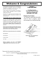
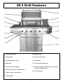
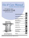
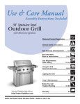
Amana™SS 5 Burner Grill w/ Rear Burner
USE AND CARE MANUAL
FOR OUTDOOR USE ONLY
ALWAYS KEEP YOUR GRILL COVERED WHEN NOT IN USE
BEFORE YOU BEGIN – We’ ve included easy-to-follow, step-by-step instructions which have been carefully written to
ensure quick assembly of your grill. Reading the instructions will be a time saver in the end.
TOOLS YOU WILL NEED – A Phillips screwdriver, adjustable wrench, 1/2” wrench or socket and a 1/4” nut driver or
socket will be needed to assemble this grill. All other necessary hardware has been included.
Questions,Missing or Damaged part? DO NOT RETURN PRODUCT TO STORE
Were here to help. Just call 1-800-229-5647. For faster service, have model number and
serial number on hand when calling.
IMPORTANT SAFETY INFORMATION
- Read this manual carefully before using your grill to reduce the risk of fire, burn
hazard or other injury.
- Extreme care should be used because of the high temperatures produced by this
appliance. CHILDREN SHOULD NOT BE LEFT UNATTENDED IN AN AREA
WHERE THE GRILL IS BEING OPERATED.
- This appliance must be kept clear from combustible materials, gasoline or other flammable vapors and liquids. Do not
allow flammable materials to come in contact with grate, burner or hot surfaces.
- Use only outdoors and provide good ventilation to avoid carbon monoxide build-up which could result in injury or death.
- Do not repair or replace any part of this appliance unless it is specifically recommended in this manual. A qualified
service technician should conduct all other service.
- Follow the installation and servicing instructions provided with this product. Have your grill installed by a qualified
service technician.
- Locate the main gas supply valve so that you know how to shut the gas off to your grill.
- If you smell gas, make sure all gas connections are tight before operation. If you continue to smell gas call a
qualified technician.
- When lighting a burner, always pay close attention to what you are doing and be certain you are pushing the igniter
that lights the burner you intend on using.
- Always keep your face and body as far away as from the grill as possible when lighting to reduce the risk of burn.
- Extinguish all flames and do not smoke while engaging gas and igniting the grill.
- A minimum distance of at least 12" must be maintained from any combustible material on both sides and the back of
the grill. Do not place the grill under any overhead unprotected combustible construction.
RECOGNIZE SAFETY SYMBOLS, WORDS AND LABELS
WARNING indicates a potentially hazardous situation which, if
not avoided, could result in death or serious injury.
NOTE indicates an important piece of information that needs to
be observed to ensure the proper operation of your grill.
INSTALLER: Please retain these instructions with the owner so that they may maintain them for
future reference.
2
Welcome & Congratulations
Questions?
Congratulations on your purchase of a new grill! We are
very proud of our product and we are completely
committed to providing you with the best service
possible. Your satisfaction is our #1 priority.
1-800-229-5647
for written inquiries:
Sure Heat Manufacturing
3130 Moon Station Rd
Kennesaw, GA 30144
Please read this Use & Care Manual very carefully. It
contains valuable information on how to properly
maintain your new grill.
We know you’ ll enjoy your new grill and thank you for
choosing our product. We hope you consider us for
future purchases.
Register Your Product
The PRODUCT REGISTRATION CARD
PLEASE READ AND SAVE THESE INSTRUCTIONS
should be filled in completely, signed
This Use & Care Manual provides specific operating
instructions for your model. Use your grill only as
instructed in this manual. These instructions are not
meant to cover every possible condition and situation
that may occur. Common sense and caution must be
practiced when installing, operating and maintaining any
appliance.
and returned to Sure Heat Manufacturing.
Please record your model and serial numbers below for
future reference. This information is found on the serial
plate located on the inside of the grill door.
NOTE: Use only soap and water to clean serial plate.
Model Number: ______________________________
Serial Number: ______________________________
Please attach sales receipt here for
future reference.
Purchase Date: ______________________________
Gas Type: __________________________________
Please complete and mail in the Product
Registration Card included with your grill.
Please retain this manual for future reference
Amana™is a registered trademark of the Maytag Corporation and is used under license
to Sure Heat Manufacturing
© 2007 Sure Heat Manufacturing
3
All rights reserved
General Safety Instructions
Do not use the rotisserie in the rain.
NOTE: Do Not operate the main burners and infrared
back burner at the same time. This can cause warping of
the roll top grill hood.
Electrical Grounding Instructions
This appliance (rotisserie motor) is equipped with a
three-prong (grounding) plug for your protection
against shock hazard and should be plugged directly
into a properly grounded three-prong receptacle. Do
not cut or remove the grounding prong from this plug.
Do not use the grill in garages, breezeways, sheds or any
enclosed area. Never operate the grill in enclosed areas as
this could lead to a carbon monoxide buildup, which could
result in injury or death. Place the grill on a level surface.
Avoid moving the grill while it is operation.
Keep any electrical supply cords and the fuel supply
hose away from any heated surfaces.
Always have a qualified service technician perform difficult
conversions or modifications.
The Spare L.P. Gas Tank Barrier must be installed to
prevent storage of spare L.P. Gas Tanks. Failure to
comply with these instructions could result in a fire or
explosion that could cause serious bodily injury, death,
or property damage.
Never attach an unregulated gas line to the appliance.
Connection to an unregulated gas line can cause excessive
heat or fire.
TESTED IN ACCORDANCE WITH ANSI
Z21.58b-2002/CSA 1.6b-M02 STANDARD FOR
OUTDOOR COOKING GAS APPLIANCES. THIS
GRILL IS FOR OUTDOOR USE ONLY.
Check your local building codes for the proper method of
installation. In the absence of local codes, this unit should be
installed in accordance with the
National Fuel Gas Code No. Z223.1-2002 and the
National Electrical Code ANSI/NFPA No. 70-1990
FOR YOUR SAFETY
If you smell gas:
1. Shut off gas to the appliance.
2. Extinguish any open flames.
3. Open grill hood.
4. If odor continues, immediately
call your gas supplier and local Fire Dept.
FOR YOUR SAFETY
DO NOT store or use gasoline or other flammable vapors
and liquids in the vicinity of this or any other appliance.
CALIFORNIA PROPOSITION 65 - WARNING: The
Burning of gas cooking fuels generates some
by products which are on the list of substances which are
known by the State of California to cause cancer or
reproductive harm. California law requires businesses to
warn customers of potential exposure to such substances.
To minimize exposure to these substances, always operate
this unit according to the use and care manual, provide
good ventilation when cooking with gas.
An LP cylinder not connected for use shall not be stored in
the vicinity of this or any other appliance.
DO NOT try lighting this appliance without reading the
“ LIGHTING INSTRUCTIONS” section of this manual.
This appliance is not intended to be installed in or
on recreational vehicles or boats.
FOR OUTDOOR USE ONLY
4
SS 5 Grill Features
1
8
3
10
2
9
11
4
12
5
6
13
7
14
1. Roll top grill hood
9. Warming shelf
3. Grilling/cooking surface
11. Side burner
2. Rotisserie kit
10. Rear Infrared burner
4. Side shelf
12. Control knob: side burner
5. Towel bar/utensil hanger
13. Electronic igniter: main burners, side burner
and rear infrared burner
6. Control knob: Rear infrared burner
14. Cart with doors
7. Control knobs: main burners
8. Hood Handle
5
Getting Started
All hardware is shown actual size.
49600206 Caster Assembly Nuts x6
49600113 Self-Tapping Screws x13
49600101 "S" Hooks x3
Two People Required to Assemble Grill
Tools Needed:
Phillips screwdriver
Adjustable wrench
1/2” wrench or socket
1/4” nut driver or socket
6
SS 5 Grill Out of Box
2a
12b
2c
5a
5b
12c
3e
1a
11b
2e
7
12a
11a
6
1b
1c
4a
2a.
12b.
2c.
5a.
5b
2e.
1a.
12c.
3e.
4a
11b
7
12a
Cart Side Left
Main Cooking Grate
Cart Side Right
Cart Door Left
Cart Door Right
Cart Back
Cart Base
Bread Warmer Grate
Spare LP Gas Tank Barrier
Grill Assembly
Drip Pan
Side Burner Shelf Assembly
Flavor Grid
11a
6
1b
1c
Condiment Basket
Side Shelf Left Assembly
Caster Assembly Left (Swivel Wheels)
Caster Assembly Right (Swivel Wheesl with lock)
Not Shown: Plastic bag containing:
Igniter Wire
Screw Packages
Side Burner Igniter
Side Burner Knob
Side Burner Bezel
Tank Ring
Open Box Carefully – Lay Out All Parts
7
STEP ONE
SS 5 Assembly
a. Set the cart base on the floor and then lay the
caster assembly left on the left side and the caster assembly right on the right side of the cart
base. The large hole in the cart base will be
towards the rear of the base.
b. Pick up the left side of the cart base and set the
caster assembly left in place by inserting the
attached bolts through the three (3) holes in the
cart base.
c. Pick up the right side of the cart base and set the
caster assembly right in place by inserting the
attached bolts through the three (3) holes in the
cart base.
1a
1b
1c
8
SS 5 Assembly
STEP TWO
a. Place the cart side left onto the two (2) outer fixed
caster assembly bolts, make sure the large flange
is toward the front of the cart base.
b. Secure the cart side left in place by hand tightening
the caster assembly nuts onto the caster
assembly bolts.
c. Place the cart side right onto the two (2) outer
swivel caster assembly bolts, make sure the large
flange is toward the front of the cart base.
d. Secure the cart side right in place by hand
tightening nuts onto the caster assembly bolts.
e. Place the cart back onto the two (2) rear caster
assembly bolts.
f. It will be necessary to push the top of the left and
right cart sides outward slightly to get the cart
back down completely on the cart base.
2f
2e
2a
2c
2b
9
2d
SS 5 Assembly
STEP THREE
The Spare L.P. Gas Tank
Barrier must be installed
to prevent storage of spare L.P. Gas
Tanks. Failure to comply with these
instructions could result in a fire or
explosion that could cause serious
bodily injury, death, or property
damage.
a. Press the cart sides back together making sure
that the cart back flange cover the cart side
flanges.
b. Attach three (3) self tapping screws through the
pre-drilled holes on the cart back into the cart
side left. Repeat for cart side right.
c. Fasten two (2) caster assembly nuts onto the back
caster assembly bolts.
d. Tighten all six (6) caster assembly nuts with a
wrench.
e. Attach the Spare L.P. Gas Tank Barrier by
inserting the tabs into the slots in the cart base
and then attach the flat end of the
barrier to the pre-drilled hole in the cart back
with a self-tapping screw.
3a
3a
3b
3b
3d
3e
10
3c
STEP FOUR
SS 5 Assembly
a. Loosen the four (4) grill mounting bolts so that there
is approximately 1/4” between the bolt head and
grill bottom.
b. Have someone help you pick up the grill and set it
squarely on top of the cart.
c. Make sure the four (4) bolts fall through the large
opening on the “ key hole” slots in the cart sides.
d. Slide the grill forward in the “ key hole” slots until
the back of the grill head matches the cart back.
Check on the inside of the cart to make sure that
both sides of the grill are flush with the cart.
e. Install two (2) self tapping screws into the top front
and right cart flanges.Repeat on the left side.
f. Tighten the four (4) grill head mounting bolts
underneath the grill to secure the grill to the cart.
close-up steps 4c - 4f
Repeat for all 4 corners.
4b
4e
4a
4c
4d
11
STEP FIVE
SS 5 Assembly
a. Place cart door left on an angle over the left side
door pivot.
b. Tilt the top of the door toward the grill, while
depressing the top door pivot pin above the door
edge.
c. Move the door slightly until the pin locks into place
in the hole on bottom of the front face.
d. Repeat steps 5a - 5c for cart door right installation.
e. The levels of the doors may be adjusted using the
nuts on the pivot points. You may need to remove
a washer on the left or right hand door to make
the doors align properly with each other.
close-up of steps 5b - 5c
5b
5a
12
5d
5e
STEP SIX
SS 5 Assembly
a. Lay the side shelf left assembly on its side with the
shelf hooks facing up. With a Phillips head screwdriver, remove screw from handle end, and then
attach one of the handle ends to the front of the
shelf. Note: Be careful not to scratch the side
of the shelf.
b. Before you slide the towel bar into place, be sure to
slide the "S" hooks over the bar. Then slide one
end of the bar into the installed handle end.
Attach the second handle end using the supplied
phillips head screw while holding the assembly in
place.
c. Place a piece of styrofoam from the packaging
inside the roll top grill hood to leave the hood
propped open slightly.
d. Attach the left shelf by inserting the four shelf hooks
into the slots on the side of the grill.
e. After inserting the four shelf hooks, press the shelf
against the grill and press downward until the
shelf locks in place. Make sure the top trim strip is
hanging all the way inside of the grill before
pressing downward.
f. Install one self tapping screw into the bottom front hole of the shelf. This will
permanently lock the shelf in place.
6g
6e
g. Install one self tapping screw into the
back hole on the shelf top. This will
lock the shelf in place more stably.
6d
6c
6a
6f
6b
13
STEP SEVEN
SS 5 Assembly
a. On the inside bottom of the side burner assembly
you will find the brass burner cap attached with
tape. Remove and set aside.
b. Feed the side burner gas supply hose assembly
through the grommeted hole in the side of the
cart.
c. Place a piece of styrofoam from the packaging in
the roll top grill hood to leave the hood propped
open slightly.
d. Attach the right side burner shelf by inserting the
four shelf hooks into the slots on the side of the
grill.
e. After inserting the four shelf hooks, press the shelf
against the grill and press downward until the
shelf locks in place. Make sure the top trim strip
is all the way inside of the grill before pressing
downward.
f. Install one self tapping screw into the bottom front
hole of the shelf. This will permanently lock the
shelf in place.
g. Install one self tapping screw into the back
hole on the shelf top. This will lock the
shelf in place more stably.
7g
7e
7c
7d
14
7b
7f
SS 5 Assembly
STEP EIGHT
a. Remove two screws from the side burner valve
assembly.
b. Carefully insert the valve assembly into the cast
side burner. You will need to angle the tube into
the burner assembly. Make certain that the hose
is pointing down when the valve is put in place.
Then push the valve stem out through the
opening in the front of the side burner shelf
assembly, lining up the holes on the valve
assembly with the holes on the side burner shelf.
c. Place bezel into place, with the "off" position
pointing up, making sure to line up holes.
d. Attach bezel & valve to side burner shelf with
screws removed in step 8a.
e. Press knob onto valve stem assembly.
8e
8d
close-up of step 8b
8c
15
8b
SS 5 Assembly
STEP NINE
a. Attach loose wire to bottom of cast burner, and then
to any of the open tabs in the igniter. Insert the
four remaining igniter wires coming through the
grommeted hole on side of the grill into the
remaining tabs in the igniter.
Note: The igniter is designed in such a way
that it does not matter which terminal tab is
used when connecting igniter wires.
b. Place the electronic igniter into the igniter hole on
the front of the side burner shelf. Make certain that
the igniter wire tabs are facing away from the grill.
Close-up of igniter wires attaching to igniter.
c. Secure the igniter in place using the plastic lock nut.
Make sure to tighten securely.
d. Install AA battery, negative side first.
e. Install spring and cap assembly and tighten
securely.
Close-up of igniter wire attaching to burner.
9a
9c
9d
9b
9e
16
STEP TEN
SS 5 Assembly
a. Center the brass burner cap on top of the side
burner head.
b. Place the side burner grate on to the side
burner tray.
10a
10b
17
STEP ELEVEN
SS 5 Assembly
a. Slide the condiment basket into the slots located
inside of the left hand cart door.
b. Slide drip pan in place.
11a
18
11b
STEP TWELVE
SS 5 Assembly
a. Insert the flavor grids into the cutouts with triangle
ridges facing up.
b. Install main cooking grates on the ledges provided
on the grill to create your cooking surface.
c. Rest bread warming grate on four (4) slots above
cooking grid.
The finished grill should look like the photo on the
cover of this Use and Care Manual. Clean the
outside of the grill using only a soft cloth and
non-abrasive soap and water or approved
stainless steel cleaner.
12d
12b
12a
12c
19
Gas Requirements
GENERAL INFORMATION
Never attach an unregulated gas line to the appliance. Connection to an
unregulated gas line can cause excessive heat or fire.
Verify the type of gas supply to be used, either Natural Gas (N.G.) or Liquid Propane (L.P.), and
make sure the serial plate agrees with that of the supply. Conversion kits are available separately
for an additional cost which will enable you to convert your grill from L.P. to N.G. or to convert your
grill from N.G. to L.P. Please see your local dealer for more information.
Always have a qualified service technician perform difficult conversions
or modifications.
For natural gas installations, an installer must supply a gas shutoff valve that is easily accessible
to the grill. All installer supplied parts must conform to local codes, or in the absence of local codes,
with the National Electrical Code, ANSI/NFPA 70-1990, and the National Fuel Gas Code,
ANSI Z223.1-1998.
All pipe sealants must be an approved type and resistant to the actions of L.P. gases. Never use
pipe sealant on flare fittings. All gas connections should be made by a competent qualified service
technician and in accordance with local codes and ordinances. In the absence of local codes, the
installation must comply with the National Fuel Gas Code, ANSI Z223.1-1998. Gas conversions kits
may be purchased separately. When ordering gas conversion kits, have the model number, and the
type of gas (N.G. or L.P.) used for your grill.
This grill and its individual shut off valve must be disconnected from the gas supply piping system
during any pressure testing of that system at test pressures in excess of 1/2 PSIG (3.5 kPa.).
This grill must be isolated from the gas supply piping system by closing its individual manual shut-off
valve during any pressure testing of the gas supply piping system at test pressures equal to or less
than 1/2 PSIG (3.5 kPa.).
The installation of this grill must conform with local codes, or in the absence of local codes, with
National Fuel Code, ANSI Z223.1a-1998.
Installation in Canada must be in accordance with the Standard Can1-b149.1 and/or .2 (installation
code for gas burning appliances and equipment) and local codes.
20
Gas Requirements
L.P. GAS INSTALLATION
Amana™Gas Grills that are set to operate with L.P. gas come with a high capacity hose and
regulator assembly. (Note: Only use the pressure regulator and hose assembly supplied with
the grill or a replacement pressure regulator and hose assemblies specified by Amana™).
This assembly is designed to connect directly to a standard 20 lb. L.P. cylinder. L.P. Cylinders are
not included with the grill. L.P. Cylinders can be purchased separately at an independent dealer.
LP hose/
regulator supplied
with complete grill
and cart.
(Type 1
connector)
L.P. TANK INFORMATION
Never use a dented or rusted L.P. tank or cylinder with a damaged valve.
L.P. cylinders are equipped with an O.P.D (Overfilling Prevention Device). The device shuts off the
flow of gas to a cylinder after 80% capacity is reached. This limits the potential for release of gas
when the cylinder is heated, averting a fire or possible injury.
The L.P. cylinder must have a shut-off valve terminating in an L.P. gas supply cylinder outlet
specified, as applicable, for connection No. 510 in the standard for compressed gas cylinder valve
outlet and inlet connection ANSI/CSA-V-1. Cylinders must not be stored in a building, garage, or
any other enclosed area. (The L.P. cylinder must have an overfill protection device, OPD, on it.)
The L.P. gas supply cylinder must be constructed and marked in accordance with the specifications
for L.P. gas cylinders of the U.S. Department of Transportation (DOT) or the National Standard of
Canada, CAN/CAS-B339, “ Cylinders, Spheres and Tubes for the Transportation of Dangerous
Goods.”
L.P. TANK USE
• When turning the L.P. tank on, make sure to open the valve SLOWLY two (2) complete turns to
insure proper gas flow. Most gas tanks now come equipped with a leak detector mechanism
internal to the tank, when gas is allowed to escape rapidly it shuts off the gas supply. Opening the
valve rapidly may simulate a gas leak, causing the safety device to activate, restricting gas flow
causing low flames. Opening the valve slowly will insure this safety feature is not falsely triggered.
• When not in use, gas supply cylinder valve is to be in the “ OFF” position.
• The tank supply system must be stored upright to allow for vapor withdrawal.
• The regulator and hose assembly must be inspected before each use of the grill. If there is
excessive abrasion or wear or if the hose is cut, it must be replaced prior to the grill being
used again.
• Cylinders must be stored outdoors out of the reach of children and must not be stored in a
building, garage or any other enclosed area.
• Only a qualified gas supplier should refill the L.P. tank.
• Do not store a spare L.P. gas cylinder under or near the grill.
21
Pre Operation Leak Testing
GENERAL INFORMATION
Although all internal gas connections on the grill are leak tested prior to shipment, a complete gas
tightness check must be performed at the installation site due to possible shifting during shipment,
installation or excessive pressure unknowingly being applied to the unit. Periodically check the
whole system for leaks and immediately check the system if the smell of gas is detected.
BEFORE TESTING
Do not smoke while leak testing. Extinguish all open flames. Never leak test with an open flame.
Mix a solution of equal parts mild detergent or liquid soap and water.
TESTING
1. Turn off the burner control knobs.
2. Turn the top knob of the fuel supply cylinder counterclockwise (right to left) two (2) rotations to
open.
3. Apply the soap solution to connections of the fuel supply assembly. If no soap bubbles appear,
there is no gas leak. If bubbles form at the connections, a leak is detected. If a leak is detected,
immediately turn off the gas supply, tighten any leaking fittings, turn gas on, and repeat steps 1-3.
4. Turn off the knob on the fuel supply cylinder.
5. Turn on the burner control knobs for a moment to release the pressure in the hose, then turn the
control knobs back off.
6. Wash off soapy solution with cold water and towel dry.
Check all gas supply fittings before each use and each time the gas supply cylinder is connected to
the regulator.
Have a qualified service technician leak test the grill any time a part of the gas system is replaced.
Also it is recommended to perform a leak test at least once a year whether or not the L.P. gas supply cylinder has been disconnected.
NOTE: When leak testing this appliance, make sure to test and tighten all loose
connections, including the side burner. A slight leak in the system can result in a low
flame, or hazardous condition. Most L.P. gas tanks now come equipped with a leak
detector mechanism internal to the tank, when gas is allowed to escape rapidly it shuts off
the gas supply. A leak may significantly reduce the gas flow making the grill difficult to light
or causing low flames.
NOTE: If you cannot stop a gas leak turn off the gas supply and call your local gas
company or the dealer you purchased the appliance from. If necessary, replace the
faulty part with the manufacturer’ s recommended replacement part. A slight leak
could cause a fire.
22
BEFORE LIGHTING
Lighting the Grill
burner between the flavor grids.
Position the match near the burner ports
and push and turn the control knob counter
clockwise to the “ HIGH” position.
(See Fig. 51-52)
Important! Before Lighting:
• Check the gas supply line for cuts, wear
or abrasion.
Note: If the grill will not light after several
attempts see the trouble-shooting section of
this manual. Turn the control knobs to the
OFF position when not in use.
• Always keep your face and body as far away
from the grill as possible when lighting.
GRILL BURNER LIGHTING
Lighting the Grill with electronic igniter
Do not attempt to “ Light” the grill if
the odor of gas is present!!
1. Make sure all control knobs are in the
“ OFF” position.
2. Open the gas supply valve located on top of
your L.P. tank.
Fig. 50
ATTENTION: When turning the L.P. tank on,
make sure to open the valve very SLOWLY
two (2) complete turns to insure proper
gas flow.
3. Always open the hood before attempting to
light.
4. Push and turn one of the control knobs counter clockwise to the “ HIGH” position and
immediately press the electronic igniter
button. You will hear a snapping sound. It
may be necessary to hold the electronic
starter button for about 4 seconds.
(See Fig. 50)
Fig. 51
NOTE: If the burner does not light in 4
seconds, turn the knob to the “ OFF” position and wait 5 minutes before trying again.
5. Repeat above steps to light remaining
burners.
Fig. 52
MATCH LIGHTING
If by chance the electronic igniter does not light
the burner, the burner may be lit with a
match. Keep your face as far away from the
grill surface as possible and place a lit, long
stem match through the spaces in the grill
grates to the ports of the back crossover
23
Crossover Burner
GRILL LOCATION
Using the Grill
Do not use the grill in garages, breezeways, sheds or any enclosed area. Never
operate the grill in enclosed areas as this could lead to a carbon monoxide
buildup, which could result in injury or death. Place the grill on a level surface.
Avoid moving the grill while it is operation.
NOTE: The grill will operate best if it is not facing directly into the wind.
Clearance to combustible construction - A minimum of 12” from the sides and back must be
maintained from the gas grill above and below the cooking surface to adjacent vertical combustible construction.
Clearance to non-combustible construction - A minimum of 6” clearance from the back of the grill
to non-combustible construction is required for the lid to fully open.
Storage of an outdoor gas cooking appliance indoor is permissible only if the cylinder is
disconnected and removed from the appliance.
GENERAL RULES
Do not leave the grill unattended while cooking!
1. Make sure the grill has been leak tested and is properly located.
2. Light the grill burners using the instructions provided in this manual.
3. Turn the control knobs to desired temperature “ High, Medium, or Low” and preheat the grill for
10 minutes before cooking.
4. Adjust heat settings to meet your cooking needs for desired results.
5. Allow grill to cool down, wipe off any splatters or grease and clean the drip tray as needed.
6. Do not put a cover on the grill while it is still hot as it could start a fire.
Keep any electrical supply cords and the fuel supply hose away from any
heated surfaces.
24
Using the Rotisserie
The grill rotisserie system is designed to cook items from the back using infrared heat. The rotisserie burner is an
infrared type which provides intense searing radiant heat. Preferred by chefs over other cooking methods, this intense
heat sears in the natural juices and nutrients found in quality cuts of meats.
Remove the warming rack from the grill when using the rotisserie to prevent
warping from the intense heat of the infrared unit.
NOTE: The rotisserie spit rod is centered between the grill hood and the burners. It may be necessary to
remove the grates and flavor grids when cooking larger portions of meat on the rotisserie. This is by design,
since this configuration gives you the most possible room above and below the rod for larger pieces of meat.
Once lit, the rotisserie burner will reach cooking temperature in 1 minute. The orange/red glow will even out in about 5
minutes. The rotisserie motor is equipped with metal gears and is capable of turning up to 12 lbs. of food. The motor is
mounted on a bracket on the left side of the grill by sliding the motor over the bracket with the cord facing the back of
the grill. Make sure the rotisserie motor is completely seated on the bracket prior to operating. Make sure the rotisserie
cord is away from any hot surfaces.
Electrical Grounding Instructions
This appliance (rotisserie motor) is equipped with a three-prong (grounding)
plug for your protection against shock hazard and should be plugged directly
into a properly grounded three-prong receptacle. Do not cut or remove the
grounding prong from this plug.
ATTACHING THE ROTISSERIE
Fig. 53
The motor is mounted on a bracket on the left side of the
grill by sliding the motor over the bracket with the cord
facing the back of the grill. (See Fig. 53)
With the rotisserie motor in place and plugged into an
electrical outlet, it is now ready to operate. Slide one of the
meat forks onto the rod (prongs facing away from the
rounded end). Push the rod through the center of the food,
then slide the second meat fork onto the rod (prongs
toward the food). Center the food to be cooked on the rod,
then push the meat forks firmly together. Tighten the
thumb screws. It may also be necessary to wrap food with
butcher’ s string, (never use nylon or plastic string) to
secure loose portions. (See Fig. 54)
Fig. 54
Pointed End Of Rod
Once the food is secure, insert the pointed end of the
rotisserie rod into the motor assembly and rest the other
end on the support on the right-hand side of the grill.
(If needed, remove the cooking grates for more room).
Turn the power switch to the “ On” position to start the
rotisserie motor.
NOTE: Remove the rotisserie when not in use. Store
the unit indoors when not in use. Remove warming
shelf when using rotisserie.
Do not use the rotisserie in the rain.
25
Accessory Lighting
ROTISSERIE LIGHTING
Open the lid. Push and turn the control knob for the
rotisserie counter clockwise to the “ HIGH” position.
Wait 5 seconds. Then press and hold the electronic
igniter button. You’ ll hear a snapping sound. If the
burner does not light in 4 seconds, turn the control
knob to OFF and wait 5 minutes before trying again.
Once lit, turn the control knob to the desired setting.
(See Fig. 55)
If the igniter does not function, the burner can be lit by
holding a lit match to the burner while the control knob
is turned counter clockwise to “ HIGH” . (See Fig. 56)
NOTE: After the first use the stainless steel around
the burner will darken. This is a normal reaction of
premium stainless steel to heat and is not a defect.
The infrared panel will also darken after initial use.
This is also a normal occurrence.
Fig. 55
Fig. 56
NOTE: Do Not operate the main
burners and infrared back burner at
the same time. This can cause
warping of the roll top grill hood.
SIDE BURNER LIGHTING
Push and turn the side burner control knob to the
“ HIGH” position and immediately press and hold
the electronic igniter button. You’ ll hear a
snapping sound. It may be necessary to hold the
electronic starter button for about 4 seconds. If
the burner does not light in 4 seconds, turn the
knob to the “ OFF” position and wait 5 minutes
before trying again. Repeat above steps to light
remaining burners. (See Fig. 57)
MATCH LIGHTING OF THE BURNER
If by chance the electronic igniter does not light the
burner, the burner may be lit with a match. Keep
your face as far away from the burner as possible
and place a lit, long stem match through the
spaces in the grate to the ports of the burner.
Position the match near the burner ports and
push and turn the control knob to the “ HIGH”
position. (See Fig. 58)
26
Fig. 57
Fig. 58
DRIP TRAY
Care and Maintenance
The drip tray located below the grill, inside the cart, should be cleaned periodically to prevent heavy
buildup of debris.
Note: Allow the drip tray to cool before attempting to clean.
Important: Do not leave the grill outside during inclement weather unless it is covered (cover
sold separately). Rain water can collect inside of the grill, the grill cart or the drip tray if left
uncovered. If the drip tray is not cleaned after use and the grill is left uncovered, the drip
tray will fill with water causing grease and water to spill into the grill cart. We recommend
cleaning and storing the drip tray after every use.
COOKING GRATES
The cooking grates can be cleaned immediately after cooking is completed and after turning off
the grill. Wear a barbecue mitt and scrub the cooking grates with a damp cloth. If the grill is
allowed to cool down, cleaning the grates will be easier if removed from the grill and cleaned with
a mild detergent.
STAINLESS STEEL
After initial usage, areas of the grill may discolor from the intense heat given off by the burners,
this is normal.
Purchase a mild stainless steel cleaner and rub in the direction of the grain of the metal. Specks of
grease can gather on the surface of the stainless steel and bake on to the surface and give a worn
appearance. For removal, use an non-abrasive oven cleaner in conjunction with a stainless cleaner.
Note: Always scrub in the direction of the grain.
Note: Always keep your grill covered when not in use.
IGNITER ACCESS
(UNDER SIDE BURNER SHELF)
To remove igniter, unscrew igniter push button and
locking nut from front panel of the side burner and
igniter will fall out through the bottom
REAR INFRARED BURNER
Light and burn the rear infrared burner at least once a month to ensure there is not a build-up of debris or grease on the
burner. This will ensure the ceramic burner will continue to operate as it should.
PORCELAIN PARTS
Certain parts of your Grill have a porcelain coating. Porcelain is a glass-based product, and is highly
durable to standard wear and tear. However, porcelain is sensitive to concussive blows, which can
create interlaced micro-fractures, or “ spider-webs.” Please take care not to strike any porcelain
covered parts with solid objects, drop them, or create any other concussive blows. These interlaced
micro-fractures are common and may lead to minor chipping. Neither the chipping nor the interlaced
micro-fractures will adversely affect the performance or your grill, and are not covered under the
warranty for porcelain parts.
27
Troubleshooting Your Grill
GENERAL TROUBLE SHOOTING
You should inspect the burners at least once a year or immediately if any of the following conditions occur:
• The smell of gas.
• Flames appearing mostly yellow. (some yellow at the tips is OK)
• The grill will not get hot enough.
• Burners make a snapping noise.
• The grill heats unevenly.
SPIDER AND INSECT WARNING
Spider and insects can nest in the burners of this or any other grill and cause the gas to flow from the front of the burner.
This is very dangerous condition which can cause a fire to occur behind the valve panel, thereby damaging the grill and
making it unsafe to operate. We recommend you check the grill and remove any spiders, insects and webs at least once
a year to reduce this risk.
BEFORE CALLING CUSTOMER SERVICE
If the grill does not function properly, use the following checklist.
PROBLEM
Grill will not light when the igniter button is pushed.
SOLUTION
Is your gas supply turned on ?
If this is an L.P. grill, is there gas in your tank ? Check your
gas level.
Is one of your burners turned on? Allow up to four seconds
of gas flow to ignite.
Is your igniter working?
- You should hear a snapping sound when you press
the igniter?
- If you hear a snapping sound can you see a spark at
the electrodes?
Note - You will need to remove your cooking
grates and flavor grids to see the electrodes.
Check to see if your igniter battery is installed correctly
with the negative side in.
Check your igniter battery and replace if needed.
Check for loose wire connections to the igniter or electrodes.
Check to see if debris is blocking the electrodes.
If the igniter is not working can you light the grill with
a match?
28
PROBLEM
Troubleshooting Your Grill
SOLUTION
Grill will not light with a match or low heat with dial set
to "High" position.
• Is your gas supply fully turned on?
• If this is an L.P. grill is there gas in your tank ? Check
your gas level.
• If this is an L.P. grill, shut off gas supply, disconnect gas
line at tank, reconnect the line to the tank.
• Make sure all the knobs are in the off position, then
open the gas supply valve on the L.P. tank very slowly
1/4 turn, then open fully (at least two full turns). Check
flame height again.
• Check to insure the gas supply line or hose is not
kinked.
• If only one burner appears low, check and clean the
burner ports if clogged or dirty.
• Check for leaks.
Note - Pre-Heating time can take from 5 to 10 minutes.
Flame is erratic
• Check gas connection
- look for kinked hose.
- make sure gas supply valve is fully open.
• Gas level may be low.
• Grill may be in need of cleaning.
Flare-ups
• Check flavor grids and cooking grates for excess food or
grease build-up.
• Ensure grill is not placed directly in the path of wind.
• Be sure drip tray is clean, (do not use aluminum foil on
drip tray.)
Note: Some flare-ups may be inevitable if cooking
greasy foods.
Burner flame is mostly yellow or orange, possibly in
conjunction with smell of gas.
• Check the burner inlet for obstructions. Particularly at air
inlets for each burner.
• Grill may be in an area that is too windy.
Cart door does not align properly with cart
• Loosen the four 1/2” bolts under the grill hood that hold
grill to cart. Slide grill head left or right as needed until
door is aligned properly. Retighten bolts.
WARNING: Move grill head gently to the left or right
on the cart! After the four bolts have been loosened,
the grill is not attached to the cart and could fall, causing damage or physical injury.
29
SS 5 Replacement Parts Sheet
2
1
13
3
14
4
16
6
7
9
20
17
8
15
21
23
5
18
28
10
11
NS*
NS*
NS*
NS*
NS*
NS*
NS*
NS*
1.
2.
3.
4.
5.
6.
7.
8.
8a.
8b.
8c.
9.
10.
11.
12
26
29
12
19
31
Bag of 13 Self-Tapping Screws
Bag of 6 Wheel Channel Nuts
Set of 3 “ S” Hooks
Condiment Basket
Match Extender
Side Burner Igniter Wire
Back IR Igniter Wire
Hood Bolt Assembly
Rotis Motor Mount
Hood Support
Bread Warmer
Back IR Igniter
Back IR Igniter Cover
Back IR Heat Deflector
Back Infrared Burner
Main Igniter Wire Set
Main Igniter Wire 36”
Main Igniter Wire 42“
Main Igniter Wire 48“
Main Igniter Spit Holder
Igniter Grease Shield
3 Cell Burner
2 Cell Burner
13.
14.
15.
16.
17.
18.
19.
20.
21.
22.
23.
24.
25.
26.
27.
28.
29.
30.
31.
32.
33.
34.
35.
30
22
24
35
25
27
34
30
32
Hood Assembly
Spit Holder
Back IR Cover
Rotis Motor
TG 33 Main Grate
Flavor Grid
TG 33 Inner Liner Assembly
Dome Temp Gauge
Hood Support Assembly
Main Hood Handle End
TG 33 Spit Rod
Meat Fork
3 Burner Z Bar
Burner Support
TG 33 Inner Liner - Back
TG 33 Inner Liner – Bottom
TG 33 Inner Liner Left
TG 33 Inner Liner – Bottom
Front Heat Shield
Drip Pan Heat Shield
TG Inner Liner Right
2 Burner Z Bar
AL 30” - 1.5” x 24” Handle Tube
33
* Not Shown
SS 5 Replacement Parts Sheet
36
37
50
54
52
39
67
64
68
62
72
56
57
43
45
63
66
65
69
53
42
44
61
55
40
41
36.
37.
38.
39.
40.
41.
42.
43.
44.
45.
46.
47.
48.
49.
50.
51.
52.
53.
54.
55.
56.
57a.
57b.
57c.
38
51
49
46
Side Shelf Left Assembly
1⁄2” Handle End - Small
Towel Rack Tube
TG33 Front Face Assembly
TG33 Cart Back
Cart Side Left
Cart Brace
Bottom Door Stop
TG 33 Door Assembly Left
Wheel Channel Assembly Left
Wheel Channel Assembly Right
Cart Base Front Trim
Cart Base
Tank Secure Ring
Grill Head Back
Grill Head Bottom
Drip Pan
Drip Pan Guide
Small Plastic Grommet
2-Hose Regulator Assembly
Cart Side Right
Back IR Knob
Back IR Bezel
Back IR Nameplate
47
74
58
59
48
60
58.
59.
60.
61.
62.
63.
64.
65.
66.
67.
68.
69.
70.
71.
72.
73.
74.
75.
76.
77.
78.
79.
31
71
79
78
1” Handle End - Small
1” SST Tube - TG Door Handle
TG 33 Door Assembly Right
Side Burner Shelf Assembly
Back IR Gas Line
5 Pole Igniter
Side Burner Igniter
Side Burner Grate (Cast Burner)
Side Burner Cover
Side Burner Cap (Cast Burner)
Cast Side Burner Assembly
Rear Side Burner Bracket
Front Side Burner Bracket
Side Burner Valve (Cast Burner)
Main Burner Knob
Main Burner Bezel
TG 33 Main Manifold Assembly
Door Spring Pin
Magnetic Catch
Amana Logo
Main Burner Bezel
Main Burner Knob
77
76
70
73
75
Warranty
LIMITED WARRANTY
Sure Heat Mfg warrants that for the lifetime of the product from the date of purchase, the
stainless steel panels will not break due to defects in material or workmanship, and that for a period
of four years from the date of purchase, the stainless steel burners will be free from defects in
material and workmanship. All other components of this barbecue grill are warranted free from
defects in material and workmanship for one year from the date of purchase. Sure Heat Mfg, at its
option, will repair or replace this product or any component of the product found to be defective
during the warranty period. Replacement will be made with a new manufactured or remanufactured
product or component. If the product is no longer available, replacement may be made with a similar product of equal value. This is your exclusive warranty.
This warranty is valid for the original retail purchaser from the date of initial retail purchase
and is not transferable. Keep the original sales receipt. Proof of purchase is required to obtain
warranty parts.
This warranty does not cover normal wear of parts such as scratches and dents of the stainless
steel components or damage resulting from any of the following:
• negligent use or misuse of the product, including exposing the product to chemicals or cleaning
products not approved by Sure Heat Mfg
• corrosion or discoloring due to lack of maintenance, misuse, hostile environments, alterations,
accidents, or abuse or neglect
• use or installation contrary to specified instructions and applicable building codes, including
heating the product to temperatures above its rated specifications which can cause considerable
warping
• disassembly, including removal of the product from a built-in installation
• damage resulting from accident, alteration, misuse, abuse, hostile environments, or improper
installation
• repair or alteration
• acts of God, such as fire, flood, hurricanes, and tornadoes
• gas cylinders, propane tanks or other fuel delivery systems, including connections to a household
fuel supply
• usage other than single-family household use such as commercial or industrial use
• minor warping or discoloration of parts, which is normal and not a defect under this warranty
This warranty does not include transportation or shipping costs of any kind.
DO NOT RETURN THIS PRODUCT TO THE PLACE OF PURCHASE.
If the Sonoma Platinum Edition Grill does not operate properly, first thoroughly carry out the
instructions provided with the unit to ensure that the appliance is installed correctly and check the
troubleshooting section in the use and care manual.
We recommend you return the warranty registration card so that you can be contacted with any
questions of safety arise that could affect you. The return of the warranty registration card is not a
condition for warranty coverage.
If you have other questions, please contact Customer Service Hotline (800) 229-5647
Because of continuing product improvement these specifications are subject to change without notice.
51021107
Manufactured by Sure Heat
09/14/2006