1
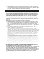
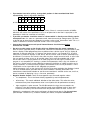
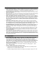
Note: this document is from the year 1994, but still valid. Only the
contact addresses and authors resumes have been adjusted.
It has been published in the MMA (MIDI Manufacturers Association)
TSBB (Technical Standards Bulletin Board) #18
---
Item #116 — Remote Control Sound Editing
Summary:
This is a list of suggestions on what future MIDI devices should be able to do and what can be
improved in existing models so that editor and librarian programs can be developed quickly and
easily, the user has a minimum of trouble and a maximum of data safety, universal editor programs
can easily be adapted, and a device s MIDI capabilities can be used efficiently.
This proposal has some overlap with Item #28 (Standardization of System Exclusive Formats), Item
#100 (Remote Control), and Item #103 (Multitimbral Set-Up) but for now will be given its own Item
number for discussion, and we will see if any of these items merge in the future.
Working Group:
Chair:
TSB Rep:
Michael Haydn
unassigned
Proposal/Discussion:
written by:
Michael Haydn, Emagic Hard- und Software GmbH
and:
Robert Melvin, Caged Artist Prod.
supported by:
Udo Hilwerling (SoundDiver Module developer)
Dr. Gerhard Lengeling, Emagic Hard- und Software GmbH
Chris Adam, Emagic Hard- und Software GmbH
Johannes Waehneldt (freelance author)
Mikail Graham
Philippe Goutier, Steinberg Software
1
Preface
1.1
Intent
Over the last few years, we at Emagic, Caged Artist (Dr. T s), and Steinberg have acquired extensive
expertise in the use of MIDI for designing sounds by remote-control. We would like to offer
suggestions on what future MIDI devices should be able to do and what can be improved in existing
models so that:
• Editor and librarian programs can be developed quickly and easily
• The user has a minimum of trouble and a maximum of data safety
• Universal editor programs can easily be adapted
• A device s MIDI capabilities can be used efficiently
1.2
How to read this document
The single items of this document are ordered in descending importance, that is, the most important
items are at the top of each section.
The text is shown in different typefaces:
Bold phrases contain the main message .
Normal typeface phrases contain explanations concerning the message , e.g. recommended
techniques.
Italic phrases are additional comments: problems that can arise for editor software or generic
editor adaptation programmers, good and bad examples.
1.3
About the authors
Michael Haydn
is the Designer/Developer of
• C-LAB Explorer 32 — an editor/librarian software (Atari) for Roland MT-32, D-5/10/20/110, E-10/20,
D-50/550
• C-LAB Polyframe — a Universal Modular Editor and Librarian Software. Dedicated Modules act like
common single editor programs, and the Universal Module PM-UNI allows adaptation to almost
every MIDI device.
• Emagic SoundSurfer — a Universal Modular Librarian Software (Atari and MacOS). Libarian-only
version of the Polyframe successor
• Emagic SoundDiver — a Universal Modular Editor and Librarian Software (Atari, MacOS and
Windows 95/98/NT/2000), the Polyframe successor. SoundDiver 2.1 supports more than 475
models.
Robert Melvin
is the Designer/Developer of
• Dr. T s X-oR Universal Editor/Librarian (Mac, Atari ST, Windows, Amiga), which supports over 100
MIDI devices with full graphic editing capabilities, and
• over 40 other individual Editor/Librarian programs
• Mark of the Unicorn UniSyn, Universal Editor/Librarian for MacOS and Windows.
Thus, both authors are self-deemed qualified experts in the area of System Exclusive.
1.4
Replies
If you have any comments, write or fax to:
Michael Haydn
Emagic Hard- und Software GmbH
Halstenbeker Weg 96
25462 Rellingen
Germany
Phone 0049-4101-495-518
Fax
0049-4101-495-199
[email protected]
Robert Melvin
Caged Artist Productions / Dr. T s
Music Software
45 Kingston
St. Somerville, MA 02144
U.S.A.
Phone 001-617-623-6941
Fax
same number
[email protected]
http://www.emagic.de
http://www.motu.com
2
Device Design
2.1
Parameter Placement
•
•
•
•
•
•
•
•
Never change a parameter s position from model to model (when the models use the same
parameters). This is of course in your own interest to keep sound cards and library disks
compatible. Avoid making changes for no good reason.
Do not group more than one data type together into one item. For example, global parameters
which determine MIDI transmission and reception (channels, filters, etc.), Drum Sets, Multi-timbral
setups, and Tuning Tables, should all be separately addressable items. This is especially true
when there are more than one of the items available. For example, if you have four drum sets,
you should be able to change one of them via SysEx without having to send all the drum sets, or
a bevy of unrelated items.
Place temporary parameters (which cannot be stored) in a separate item. In general,
parameters should be intelligently grouped. Any group of parameters which can be stored as a
group (an item or patch ) should be separately addressable in its temporary (edit buffer) location
(as well as in its stored location). If the edit buffer format contains additional data which cannot be
stored in the memory location format, the problem arises what to do with the additional
parameters if an item is copied from a memory location to the edit buffer (e.g. for auditioning).
There are ways to work around this problem, but it creates a good deal of work for the software
programmer, and the results are less than ideal for the user.
Positioning of parameters in an item data block: When designing your data structure, try to
keep parameters together which belong together. This makes copy operations easier to program.
Good example: Yamaha SY77, Ensoniq VFX, Roland D-series.
Use the same data format for parameter groups which occur in several item types.This
allows easy copy operations of those parameter groups between different data types. If one
instance is only slightly different, try to design the format to handle both cases — using dummy
bytes, if necessary. Also, if you have several different devices using similar hardware (e.g. an
effects processor), it would be useful to make the data format as compatible as possible between
devices.
Place parameters at the beginning which are decisive for the item s length or for the
relevance of other parameter groups. This makes memory allocation easier. Good example:
Yamaha SY/TG series (Voice mode). .
Plan Ahead! Add some reserved blank bytes into the data format for future models or
upgrades. Adding enough to handle minor additions is easier than introducing additional data
types with corresponding MIDI transmission, and it s better than cramming new parameters into
unused bit-fields of the old format.
If you know that you may be coming out with other versions of the product, it would be helpful to
specify (in the documentation) an extra amount of space to reserve for future formats. Many
editors and librarians use a fixed length format to store patches, so that when you come out with
a new model and increase the patch size, files created with the old model need to be converted
for compatibility with the new model. A length statement in the dump message would be helpful in
this case. At least, the message s length should be transmitted implicitly (by stating a model
code). It is useful if the old model understands the new model s messages.
Use the same data format for memory locations and the edit buffer. Different formats force
software programmers to implement data type conversion routines or tables — hard to program,
hard to understand by the (adaptation programming) user, slowing down performance, and
blowing up adaptation code. Inconsistent formats (a classic example of which are the Yamaha DX
and TX formats ) seem to be on the wane, thank heaven.
If you have a different data format for memory, provide commands to get and send data from/to
memory locations using the edit buffer format (usually less compact but more straight forward)
and/or provide commands to get and send data in the most compact format, including to and from
•
•
the edit buffer. This shouldn t be too difficult, and you ll be preventing thousands of programmer
headaches. If you provide both formats, everyone is happy — programs that can deal with the
more compact format can do so.
The different formats of the DX7 were obviously introduced to be able to address every parameter
by simply stating its offset in the item. However, today s sophisticated generic editor programs are
able to access almost every kind of bit map. Therefore, you could decide to only use the packed
format internally as well as for dumps. The only problem with this is the definition of the parameter
access. See section 3.5 for details.
Do not include completely redundant parameters in the data. Do not include any parameter
whose value is completely determined by the values of another parameter or parameters. Even if
the parameter is ignored during a bulk dump, it would still be better to eliminate it from the SysEx
format.
Do not include certain types of master parameters in the data. There is unfortunately no way
of dealing with master parameters which will be acceptable to all programmers. In general, if the
value of any parameter is dependent upon the value of another parameter (for example a master
parameter), it necessitates additional programming (in order to maintain the integrity of the dump
data block), and it becomes difficult to program universal editor adaptations.
Sometimes a master parameter is used to edit the value of a group of parameters — for example a
Master Attack Time might be used to set the Attack Times of several envelopes in a synth patch.
The user would presumably then be able to fine tune the individual attack times. In essence, the
master parameter is being used as an editing tool, but its actual value (once it has done its job) is
not important. In this case, the master parameter should probably not be included in the patch
data SysEx format, or, if included, it should always be ignored when receiving a bulk dump. The
editing program might conceivably want to implement the same master parameter mechanism, in
which case it is useful to allow the master parameter to be edited via a parameter change
message.
A second alternative in this situation is to give precedence to the master parameter, except when
the master parameter is in a designated neutral state. Using the above example, suppose that
Master Attack can be set to individual or 0-99. When the device receives a bulk dump with
Master Attack set set to individual the individual envelope attack times are used, but otherwise
the individual attack times are re-computed based on the Master Attack value (to compensate for
editors which cannot — and should not have to — do this). Internally, and in the editing program,
Master Attack should be set to individual as soon as an individual attack time is edited. This
indicates to the user (and to the unit receiving the bulk dump) that the master parameter setting
has been customized. We recommend this method for master parameters which control
particularly esoteric or complicated sets of parameters — for example, the Algorithm parameter in a
Yamaha SY-77.
Another implementation might use a Master Attack Time modifier which wouldn t change the value
of the Attack Time parameters, but would scale their actual effect. In this case, the master
parameter is a parameter like any other — it has a meaningful value (e.g. 0% to 100% or 1/10 to
10x) and it must be included in the patch data format. Editor programmers have no trouble with
this type of master parameter.
There are some cases (e.g. effects processors) where master parameters that effect the values of
other parameters are almost unavoidable. If you use this type of master parameter, please follow
these guidelines:
•
Document the effect of the master on the slave parameters —- what formula or tables do you
use internally? The Ed/Lib developer must imitate this behavior, and the job is even more
difficult when the behavior must be reverse-engineered.
•
The documentation should state which has priority in a bulk dump — the master, or the slave
parameters.
•
When a master parameter change is received, it should have the same effect as changing the
master parameter on the device. Ditto for slave parameters.
•
2.2
•
Complicated display mechanisms (combining master parameter values with slave parameter
values to arrive at displayed values) cannot easily be handled by universal editors and should
be avoided, if possible. Document any unusual display mechanisms.
Parameter encoding
Do not use non-contiguous bit fields without need unless the portions are in an accepted
format (a 14 bit word or a 16 bit word, either high or low bits first). If a parameter s value range
needs to exceed 7 bits, manufacturers often divide it into several 7 or 4 bit portions in order to
avoid the need of a transmission format overcoming the SysEx 7 bit barrier (e.g. Yamaha SY/TG
series Bias Level, Roland R-5/8 Pitch, Boss SE-50). This is o.k., since there is no other way
without other drawbacks.
If there are only a few parameters that need more than seven bits of resolution, we would prefer
to have those few parameters split up than have the entire message nibblized (or whatever
compression technique you may use). This makes the message smaller and faster, which is best
for the user.
Manufacturers use several ways to handle more-than-7-bit parameters:
a) The whole data block is converted into a 7 (or less) bit form for transmission only. As long as
this is a common format, this makes definition of an adaptation (for a universal librarian) very
easy, since the adaptation programmer only has to state the correct transmission format.
Drawback: it may inflate the size of the dump slightly (Korg, Lexicon format) or a lot (nibblized
format).
b) Only more-than-7-bit parameters are transmitted in several portions (either n + 7 bits, or
nibbles), everything else is transmitted directly.
If the data is stored this way within the device, and/or if the parameter change format is
adjusted to make it appear that this is the case(Roland R-5, R-8 Pitch), editor programmers will
most likely use the transmitted bulk format internally. The only drawback to this is that it slightly
complicates parameter access. Instead of using access formats directly supported by the
processor, the access is composed by several bit field accesses and shifts. All but the most
generic software can handle this, but it does take a little work on the part of the (editor)
adaption programmer.
On the other hand, if parameter numbering is based on internal parameter offsets, but the
internal parameter offsets are not the same as the offsets in the dump format, there are
choices to be made (which is not necessarily good). Some programmers will reconstruct the 8
bit data when a dump is received and deal with it that way (this requires special receive and
transmit format conversions). Others will store the dump the way it comes in, and deal with the
parameter access and parameter numbering quirks via a table or algorithm.
We have a strong preference for the former situation, in which the parameter number directly
relates to the offset in the dump, rather than the offset into the device s memory. Good
example: Roland.
•
Do not split individual parameters into separate bit-fields except when necessary. Do not
split up parameters which use less than 8 bits or just in order to save space.
Some older synths went to great lengths (presumably to save memory) to pack all parameters into
the smallest possible dump. This sometimes resulted in parameters being spread over many
bytes. Now that memory is cheaper and none of us has the time to be that obsessive anyway, we
hopefully won t be seeing much of this any more. Although most today s generic editor programs
are able to treat such a case, this is hard to understand and define for novice adaptation
programmers. Bad examples: Roland a Juno, Ensoniq ESQ-1
•
If parameters have to be split up, arrange their portions in the transmitted data block
consecutively, either in big endian (Motorola)
6
5
B
A
9
8
7
4
3
2
1
0
4
3
2
1
0
B
A
9
8
7
or little endian (Intel)
6
5
format (examples are for a 12-bit parameter). It s okay if there is a constant number of MSBits
which are not used or if the parameter s LS bit is not placed at bit 0 of the LS byte (that is, the
parameter is shifted as a member of a bit field).
•
•
•
•
If possible, parameters should be stored in a format which is directly accessible by popular
microprocessors. As soon as a parameter needs more than one byte storage space, you have
to decide how to place the bytes: Motorola big endian order or Intel little endian order. For us, it
makes no difference. However, Motorola format is much more popular.
Conversion from and to unusual special internal formats should be done before
transmission via MIDI.
Do not use value ranges on the display which are different from the stored parameter (in
order to save a numerical place). In other words, show the full resolution of your parameter in your
device s display. Editor programmers have a problem when a device uses 0..99 in its display to
represent an internal value of 0..127 (quite a few devices do this, e.g. Ensoniq VFX). A typical
editor tries to imitate the displays on the device, but the controls used to edit the parameter may
be different. For instance, the control in the editor may be a simple numerical value, in which case
the user would not have access to all possible values which might be available with a slider.
On the other hand, if the programmer of an editor program uses the higher resolution, the
program is not compatible for hacking in printed sound parameter charts. Also, the imitation of
the device s display usually needs additional programming (definition of a MIDI resolution and a
display resolution). In universal editor programs, the definition of this kind of parameters is more
complicated or even impossible for the adaptation programmer.
Some instruments (such as the Lexicon LXP-15) have a lot more resolution than displayed, which
can be a valuable feature, provided that this extra resolution is actually perceivable. The
manufacturer should decide whether or not this extra resolution is valuable to the user, and if so,
devise a method of displaying it (e.g. a fine tune parameter).
Negative Number formats: there are three popular ways to encode negative values:
•
2 s complement . This is the format directly supported by most microprocessors.
•
offset binary . This needs additional definition of the offset value. This offset has to be
subtracted every time the parameter value is used (notice this for performance reasons).
•
Sign magnitude is quite unusual. The MS Bit contains the sign, the rest contains the
mantissa. Using the parameter value normally needs some additional code (if..then..else).
Confusion can arise by the fact that there are two possible values for zero: +0 and —0.
Although 2 s complement is the most usual format, all three formats are o.k. Do be consistent
(bad example: Yamaha SY77), whatever method you choose, and please document it.
2.3
•
•
•
•
•
•
•
•
Names
Please use ASCII for names. It is painful to support devices which don t. Using own character
codes requires specific adaptations in universal editors. Using ASCII also makes the names visible
in standard utilities such as file viewers — as long as no transmission format is used.
Don t pack other data in with the name (in the unused bits per character). Bad example: Roland
Alpha Juno-1/2/MKS-50
Don t pack names, e.g. shift the 7-bit ASCII bytes in one big bit field. This again needs additional
programming for showing the names in a bank display. Bad example: Ensoniq SQ-1/2/R
Always store ASCII in contiguous byte-sized characters. It s fine with us if you mix lengths of
fields in your data structure — use a char (byte), or an int (short) or a long, whatever is appropriate,
but not for names! In the E-mu Proteus, each character is stored in a two-byte word instead of a
byte. It sort of makes sense in this case, because all parameters are 14-bit. However, it creates
more work for 3rd party programmers, and wastes space as well.We would have preferred a more
compact format.
All item types should have names. Computer users would be happy if all items had names,
even if the name isn t visible on the device s display. That way, when a computer sends an item
and subsequently receives it back from the device, the item will be identifiable by its name. Names
are also important for users of editor software supporting libraries. Bad examples: many!
Use fixed-length names. The preferred name is fixed length, all valid ASCII (spaces at the end if
necessary). All generic software should be able to deal with this. C or Pascal strings may be
problematic for certain software. Fixed-length names also ease programming, bank display and
name editing.
Don t use special symbols outside of the 7 bit printable international ASCII codes (32..126),
since the representation differs from computer to computer. Bad example: Roland U-20 (Note
symbol), Ensoniq ESQ-1
Fill up name fields with spaces (ASCII 32). Using an ASCII 0 instead of spaces at the end of a
name prevents us programmers from using standard functions to output a name on the screen or
printer. This slows down performance and complicates programming. An ASCII 0 at the end of a
fixed number of printable ASCII characters is o.k. — as long it is well documented (which is not the
case with the Lexicon LXP-1).
2.4
•
•
Display Software
Display routines (or any other routines) should never cause MIDI receive overrun errors
(e.g. missed SysEx messages). Temporary MIDI received messages should be programmed in
such a way that the device keeps processing MIDI data while the message is displayed.
In other words, don t let your display software, or any other routine, take over long enough to
cause a MIDI error. If the display is writing at the interrupt level and it needs to have higher priority
than MIDI, or if it needs to disable MIDI interrupts, you ve got a big problem. Other than that,
there s no excuse for allowing MIDI overruns to occur. This gets into the topic of timing, which is
discussed in the next section.
Good example: all Yamaha devices. Bad example: Ensoniq VFX ( Writing program ... please
wait... ), Korg Wavestation
A device s display should reflect incoming messages:
•
In general, if the current page shows any item (e.g. a patch name or a parameter) which is
changed via Sys. Ex, the item should be re-drawn.
•
Parameter changes should be reflected in the display. Good example: Yamaha SY77, DX7.
•
If you get performance problems, use an intelligent redraw system which queues redraw
events and redraws only the necessary area of the display. Consider implementing a slight
delay so that multiple parameter changes result in fewer display redraws. Otherwise, display
may lag behind when many parameter changes are received.
•
Strictly optional: the display could show the page where the changed parameter is displayed.
Good example: Yamaha SY77, DX7.
That type of feedback is nice for the programmer testing his software, or for the user entering
SysEx codes into his sequencer. However, switching the display page can also be a major
annoyance for the user who wants to control a certain parameter live from the keyboard, while
a sequencer changes other parameters. Ideally, this feature would be user-selected via a
SysEx parameter.
Problems arise if the Parameter change format transmits whole bytes instead of single
parameters, and bit-mapped parameters are displayed on different pages. In this case, the
SY77, for example, jumps to the wrong page. A solution is to analyze which of the transmitted
parameters has been changed, and jump to the corresponding page.
Come what may, the display software should be able to handle a dense variety of parameter
changes and other SysEx without crashing, getting behind, or mission incoming MIDI messages.
3
MIDI Communication
3.1
Overall MIDI Behavior
It seems that some manufacturers have never heard about interrupt-driven input buffers. At least,
many devices behave rather oddly when receiving certain MIDI data.
• MIDI Overrun handling: It would seem that a polling technique is often used, instead of using
interrupts. Whether you use polling or interrupts, software designers must make sure that they
don t allow overruns to occur. If an overrun does occur, handle it gracefully. It s up to you whether
or not you turn all notes off, issue an error message, etc., but, for heaven s sake don t continue to
parse the data as if nothing happened.
• Of course, MIDI devices should not crash just because there is MIDI data coming in while the
device is busy.
• Devices should not crash if they receive SysEx data which is not dedicated to them. Bad
example: Ensoniq VFX sometimes crashes if it gets Yamaha SY77 dumps.
• There should be very few cases where a device ignores certain MIDI input. There should be
no specific data transfer mode . This makes complete remote control by a computer impossible.
Bad example: Roland D-50 (Bulk Dumps are only processed in Data Transfer Mode), Roland D-70
(all SysEx messages are ignored while sound is produced). Good example: The D-110 can
receive bulk dumps even while playing a sequence!
• Use a device ID. Some editor programs are able to handle several identical MIDI devices
simultaneously. At least, a Device ID is important when parameter changes simultaneously control
several devices of the same model (which is common in contemporary MIDItasking systems like
C-LAB Softlink, Steinberg M*ROS, Emagic AutoLink, Opcode OMS). Bad example: Oberheim
Matrix series
• Necessary delays after a dump has been received or a certain action has been initiated should
be as short as possible. These delays are apparently caused by software in the device not
serving the MIDI (serial communications) hardware properly (buffering the input) while handling the
previous incoming message.Long delays cause the programmer to spend a lot of time finding out
the best delay value, and disturb convenient monitoring of sound libraries. Bad example: Korg
Wavestation (after a dump, a pause of 2,4 seconds is needed)
Those delays should be documented accurately by the manufacturer. Roland, to their credit,
documented this delay time in several of their synths. Unfortunately, they stopped. With Yamaha,
Korg, Ensoniq and many others, we must find the magical delay values that work. When we
support a device, determining the necessary delay after MIDI messages is often our number one
problem.
• MIDI input buffers should be large enough (say 256 bytes, better 4K). The device should
behave correctly if the buffer overflows. Good example: all Yamaha devices (they show a
message MIDI input buffer overflow ), Roland devices. Bad example: Ensoniq VFX (sending two
Presets subsequently causes a crash).
• It should be possible for the user to change, via SysEx, the channel on which a device
receives Channel Voice messages (without also altering the SysEx channel). Most devices
today, by virtue of being multi-timbral, satisfy this requirement, more or less. However, the best
solution is to have a completely separate device I.D. for SysEx. This is very important now, and
will only become more important as users become more sophisticated.
• Don t change SysEx reception status, local mode or memory protect status at power-up,
especially if this also means that parameter change messages would be ignored that reactivate
SysEx reception. In this case, the user would have to switch it on manually. Bad examples:
Yamaha SY77, Ensoniq ESQ-1
This is good recommended practice, even though SysEx enable at power-up used to be against
the law .
•
•
We leave the question of whether or not memory protect is automatically always enabled to the
manufacturer. If it is enabled at power-up, there must be a SysEx message to disable it, and it
should be easy for the user to turn it off without having to go through layers of menus when the
user first attempts to store something. Or, do like Roland did on the D-110: ignore memory protect
as far as SysEx is concerned.
Always transmit complete SysEx messages (including EOX). It s the law! Bad examples from
the dark ages of MIDI: Sequential Prophet-5, Casio CZ series
There should be no large gaps within a single SysEx message. Otherwise, a program could
get timeout problems. Anything over 100 milliseconds should be considered a large gap. Bad
example: Lexicon LXP-5 bank dump (pauses for 3 seconds between header and data bytes).
3.2
Dumps and Dump Requests
The best implementation :
The best implementation provides individual messages for every stored item, along with request
messages that can request an individual item, or a bank of items, or all items. This method is the most
flexible we ve encountered — it allows the editor/librarian to do every task it is supposed to do, with the
utmost in speed. Also, it should be very simple to implement. Every generic storage device and
program can easily deal with a bank comprised of multiple single-patch messages.
If you re not going to have separate temporary storage areas (edit buffers) for all sounds within a
multi-timbral setup, individual item addressing allows the editing program to directly access these
sounds without getting or sending an entire bank.
Bank dumps (all in one message) are redundant, and are not necessary. When starting a sequence,
it saves time if all the user needs to send are the items which are actually going to be used by the
sequence.
• Supply dumps and dump requests for all data types and memory locations. Single dumps
also make it easy for remote memory manager programs to copy or swap memory locations.
You are right if you say that requesting a single memory location can be achieved by sending a
program change and then requesting the edit buffer. But this is not a very safe technique:
•
•
The device may have several program change modes
•
The device may have disabled reception of program changes
•
The device may use a program change table. If there is no way to disable it, there is no way
to safely recall or store a single memory location.
•
If the editor program does not have a specific data transfer mode, it has to memorize (after
the above mentioned dump request) that the following edit buffer dump is not what it seems
to be.
•
If the editor program wants to store an item in a specific memory location, a Write request
message is needed. Often, this message must be synthesized by several remote key
commands.
Never require a combination of SysEx and program changes, or any non-SysEx messages,
to do functions which should be accomplished by SysEx alone.
If there are no single dumps for the memory locations, it would be a good idea to include a SysEx
type of program change in your spec (as well as a corresponding Write command). These
commands are not limited by channelization, program change tables, and they can directly access
all possible storage locations (and edit buffer locations, if applicable).
Program changes (sent hiddenly by an editor software) can cause severe confusion in a complex
MIDI system. It is a common technique to layer several devices on the same MIDI channel, so a
program change sent to a specific device can have side effects to other devices. The same is true
for RPN and NRPN controllers. Of course, those messages are optional if there is a way to
•
•
•
•
•
•
•
•
achieve the same result by a SysEx message. In general, you should avoid the necessity to send
MIDI messages which do not include the SysEx device number.
Use handshake protocols only if necessary, that is if the data size to be transmitted is very
large and of a variable nature (eg samples, sequencer data). If possible, make the handshake
optional (the editor should have the option to handshake if the unit can be automatically
connected, which should allow for a faster and more reliable dump, but it shouldn t be required).
Supply dumps for edit buffers. This is the safest way to audition a sound. It is also very useful in
sequencing for providing identical playback independent of the current memory configuration. The
normally used workaround (write to a specific memory location, and then transmit a program
change) steals one memory location and is not very safe (see above).
Supply dump requests for edit buffers. Often a user edits a sound at the device itself, and then
feels that editing a specific part of the sound would be easier to handle with an editor program. It
is very annoying if the transfer is not possible directly. Dumps and dump requests for edit buffers
are essential. If, for some reason, you don t have your data conveniently organized into an edit
buffer, fake it!
Supply dumps and dump requests for ROM items (at least their names). Although this might
sound strange, it s useful for showing the names of linked items. If these names are downloaded
from the device instead of being hardcoded into the editor, it s less work and will always be
correct even if a new model with new presets comes out. Also, it will be easy to remotely get a
preset item as a basic patch for editing. Good example: E-mu Proteus, Yamaha SY77 (except
Micro Tunings!), Waldorf microWave
Supply dumps and dump requests for data cartridges. Editor programmers would like to
support devices data cartridges. Ideally, the data cartridge should appear to the computer as an
extension (another bank) of internal memory. Often, a device does not support a direct MIDI
transfer of the data contained in the card or cartridge. When faced with this situation, the software
developer either decides to abandon support of the cartridge, or resorts to a kludge (if one is
possible — such as using a program change and requesting the edit buffer — assuming there is an
edit buffer).
The best way to supply dumps/requests for data cartridges is to include a bank select byte in
your SysEx item addressing if you have carts or multiple banks. Allow access to individual
cartridge items (request or dump — see above comments), the same as you do for internal memory
items. Good example: Kawai K1, K4
If cart reading/writing is slower, and causes a need for additional delays, note this in the
documentation.
Try not to change the enumeration of the items from model to model. This complicates
programming software which handles any of the available models, and causes additional work
when items are moved from one model to another (links have to be modified). Example: E-mu
Proteus 1, 1XR, 2, 2XR.
Make it possible to request the device s ID number, local control status, and poly mode
receive channel. The idea is to make it possible for software to scan a whole MIDI setup, and
completely automate the process of setting up. To do this, the software must have intelligent
control of the MIDI interface and/or patchbays, and each device must be able to report its ID
number, etc. It normally means that the device has a global setup which contains these
parameters, and which can be requested. See also section 3.6 Universal Device Inquiry . Good
example: Yamaha SY77.
Recalling links: If an edit buffer dump is received containing links to other memory locations,
those should be recalled automatically if
a) you do not have individual edit buffers for the linked areas, or
b) the selected link is a preset.
However, if you have individual edit buffers for all the linked areas, the best solution would be to
make it optional. The Waldorf microWave does this by offering two messages, one which includes
the link data, and one which doesn t.
•
•
•
3.3
•
•
•
•
•
The benefit in not recalling a link with individual edit buffers is a potential small time savings. With
optional link recalling, the unit doesn t have to go through the process of loading all the links and
setting up all the sound making hardware, only to have it all changed a millisecond later. This
could make for a very rocky transition depending on how the instrument handles notes which are
being held, and notes which may be triggered between the SysEx messages.
Although we ve never seen it in an existing device, we could also imagine an external setting for
each link, which would indicate that the data for that link came via SysEx. This approach has
other side benefits (for example, the device s display could show where the data actually came
from, rather than showing a memory location).
Another way to make it optional (sort of), and avoid a double-load (when SysEx data immediately
replaces the automatically recalled data): Cancel the auto-recall if the appropriate SysEx data
comes in within a specified interval.
If you can t devise a way to make it optional, please do recall the links automatically. (Better a
double-recall, than no recall at all.)
Good example: Roland D-10/20/110. Bad examples: Roland U-20, GR-50, Yamaha DX7II
If an item is variable-sized, include a length statement in the header. This makes memory
allocation easier. Good example: all Yamaha devices
Devices should be able to actively dump data. This allows sequencer programs to be used as
data storage devices. Of course, this only works if there is no handshake protocol.
If an item is linked to other items, it is sometimes helpful if all these items are transmitted
consecutively when a request is received. This is mainly for simple generic SysEx utilities in
which the user programs a request string, and the message received is recorded. Later on, when
the user plays back the message, the user expects it to restore all the pertinent data.
On the other hand, if requesting an item causes other items to be sent, this makes an intelligent
program like a Universal Editor somewhat less efficient, since it may not need all the extra
information. The best compromise may be to include a special request message which sends the
entire current state of the device (all items which affect the current sound, including edit buffers
and memory items linked to edit buffers). That way, the user of a dumb SysEx utility can easily
request a multi-item dump which will restore the device to its current state. Good example:Waldorf
Microwave Arrangement.
Checksums
Use 2 s complement for checksum transmission. A 2 s complement checksum of transmitted
bytes is the checksum format used by most manufacturers and thus a de-facto standard. Using
new checksum formats may force an update of some universal editors. At least, it complicates the
creation of adaptations.
Use checksums for large data blocks — or even better: Do not define large single SysEx
messages. Data packets should be kept down in size. We recommend on the order of 256 bytes.
Sending 60KB in one message, especially at full baud rate, is asking for trouble (with or without
checksum) — the receiver may have to shut down normal operations (or slow to a crawl), or be
specially programmed to handle such a situation. Bad example: Ensoniq VFX transmits a whole
program bank (more than 60 KB transmitted data) without a single checksum; Waldorf microWave
All Dump
Use a checksum which sums up transmitted bytes (not how they are stored internally). This
method makes the calculation of checksums easier (it can be done in the loop which receives or
sends data bytes).
Checksum errors should be notified. This helps programming the MIDI communication. Good
examples: all Yamaha and Roland devices, Lexicon LXP-1/5
Document exactly what is summed up and what is not. Including header bytes in the
checksum may cause some problems for certain universal program (most likely not, since there are
existing Roland and Yamaha formats which do this, but still we don t recommend it).
3.4
•
Transmission Formats
Transmission format preference list: We recommend the following transmission formats in
descending preference:
•
no transmission format at all: use 7-bit values internally for all your parameters, going to 14
bits only for parameters that need the extra range.
•
8/7 bit packed format (used by Korg M-1, T-1, and Lexicon LXP-1 and PCM-70). If you have
a lot of 8-bit data, please consider using this format. A group of 7 bytes
A7
A6
A5
A4
A3
A2
A1
A0
B7
B6
B5
B4
B3
B2
B1
B0
C7
C6
C5
C4
C3
C2
C1
C0
D7
D6
D5
D4
D3
D2
D1
D0
E7
E6
E5
E4
E3
E2
E1
E0
E7
F6
F5
F4
F3
F2
F1
F0
G7
G6
G5
G4
G3
G2
G1
G0
is transmitted in 8 MIDI bytes
0
G7
F7
E7
D7
C7
B7
A7
0
A6
A5
A4
A3
A2
A1
A0
0
B6
B5
B4
B3
B2
B1
B0
0
C6
C5
C4
C3
C2
C1
C0
0
D6
D5
D4
D3
D2
D1
D0
0
E6
E5
E4
E3
E2
E1
E0
0
F6
F5
F4
F3
F2
F1
F0
0
G6
G5
G4
G3
G2
G1
G0
MSBit Byte
A group of n < 7 bytes is transmitted in 1+n bytes. Thus, a block of n bytes is transmitted in
int (n/8) * 8 + n mod 7 + 1 bytes. This is the most efficient way to transmit 8 bit data in SysEx
messages, and it s fairly easy to implement. It only takes one or two more processor
instructions per byte than nibblization. Please use exactly the same format used by Korg and
Lexicon.
•
Nibbles (either low or high nibble first). This format is rather inefficient — it hogs the MIDI
bandwidth. It is easier to read (than the 8/7 scheme) in its raw form, if that makes any
difference to anybody. For some devices, this format might be desirable, since it guarantees
that data will come in at no faster than half the MIDI rate. (If you are tempted to nibblize for
this reason, we suggest using smaller packets and specifying delay times between packets
instead.)
Do not use the following transmission formats:
•
ASCII nibbles. It is a weak argument to be able to read a hex listing in a program which
displays the ASCII code of SysEx dumps, since most up-to-date programs can display the
dumps in Hex notation themselves. The big disadvantage is bad performance.
•
Alesis format — they make a 56-bit word out of 7 8-bit bytes, then chop it into 8 7-bit bytes to
send it. Don t use this format — although it is conceptually simple and just as efficient as the
8/7 bit packed format, it s slightly slower (to encode or decode), more difficult to implement
and just not common.
•
•
Use packets: MIDI messages should be structured such that a minimal amount of data is sent in
one packet (256 bytes or thereabouts would be reasonable). Bigger messages should be
separated into multiple packets. This lessens the load on merging devices (or software), and
allows the music to continue (albeit jerkily, unless packets are carefully placed). Roland s protocol
does this nicely.
Consider having a continue flag in the header which indicates that the message has more than
one packet. The next message could be the same header with a different flag, or a shorter
continued message packet , which could have a minimal header.
3.5
•
•
•
•
•
•
•
•
•
Any other format. Any new format you might invent will force the user to create conversion
routines or tables, which means additional work and poor performance. You may even force
an update of universal editor/librarian programs, and you don t want to do that!
Parameter Changes
Supply parameter change messages for all edit buffers of the device. Good example: all
Roland devices using Roland SysEx format, Yamaha SY77 (except Sequencer Setup).
If there is no edit buffer, supply parameter change messages for each memory location.
Good example: all Roland devices, Yamaha SY77 Pan, Micro Tuning
Never change parameter numbers from model to model. This complicates programming the
transmission of parameter changes and MIDI monitoring. Bad example: Ensoniq VFX —> VFXSD
—> SD-1 SysEx enable switch.
Do not use security dialogs when parameters are changed via MIDI. The security dialog can
be generated by the editor itself.
Parameter change messages should be as short as possible. This increases MIDI
performance.
However, short parameter changes should not be the ultimate goal. Address space within the
header should leave room for expansion, and separate header elements (unless closely related)
should not share one byte.
Problems can arise if a manufacturer has developed a lot of models, so he has to think about
whether to use the model ID separately or encode the model implicitly in the parameter change
type byte. Both methods are o.k.
Good example: Yamaha DX7 (7 bytes). Bad example: Ensoniq VFX (19 bytes)
Do not use variable-sized formats for the parameter value. These formats (e.g. decimal ASCII
with leading zeros omitted like the Korg Wavestation does) cannot be defined in some universal
editors.
Do not combine parameter value bytes with other data (fixed values as parameter or element
number). This requires the use of a binary value offset which is difficult to understand for the user.
Parameter changes should be transmitted by the device when the user changes a
parameter. This offers several advantages:
•
MIDI monitoring : editor programs can be used as data monitors . The data in the computer
stay synchronized even when the user continues editing at the device.
•
Learn function: When designing an adaptation for a universal editor, the definition of the
parameter change message can be automated by an intelligent routine which finds out the
value bytes. Even the parameter value range and value transmission format can be analyzed.
If the device has an option to switch realtime parameter changes off (since it may affect timing
when notes are being played simultaneously), this would be good, as long as the option is
independent from other options (we recommend that the default (factory) setting is on ).
Parameter changes should be transmitted as often as possible. This increases the usefulness
of parameter changes in sequencer programs as a performance tool.
•
The parameter number should reflect the parameter s offset in the item as closely as
possible. Incoming parameter changes can be processed much faster than scanning through a
huge table of messages. Good example: Yamaha DX7, all Roland devices. We especially do not
like formats which use a display page and slot number as the parameter number.
•
Parameter change numbers for bit mapped parameters:
Some manufacturers (Ensoniq, Lexicon, Oberheim) use parameter change messages which only
change one parameter, even if it is stored among others in one byte. The advantage is that tools
like the Notator RMG or the Cubase Dynamic MIDI Manager can change this parameter without
affecting the other parameters in the byte. But be aware that editor programs then need a
conversion table to get from a parameter number to the correct offset and bit number, and vice
versa.
One (unrecommended) solution is to un-bitmap an item if it is copied into the edit buffer (Yamaha
DX7). But this complicates the creation of adaptations with universal editors since two data types
and their conversion have to be defined.
Other manufacturers (Roland s newer models) offer separate address areas where one parameter
is virtually present in one byte. This is o.k., but universal editors which have specific Roland
support and thus don t need a parameter change message definition for each parameter (since it
is implicitly defined by the parameter offset) won t be able to allow MIDI monitoring (receiving and
processing incoming parameter changes), since the device uses completely different addresses.
A third method is the one which was introduced with the Yamaha TG33. There, the parameter
change message contains a binary mask so that the advantages of both techniques are
combined in one message format. Future universal programs with specific support could allow
easy-to-define editors, combined with MIDI monitoring. This method would even allow a universal
program to automatically find out a parameter s position (including bit mapped parameters) in an
item data block.
Separate parameter numbers for every parameter are easier for the sequencer users who enter
the parameter change manually. (The mask idea introduced in the TG33 is a bit more difficult for
the average user to grasp.) It probably also makes it easier for the receiving device to process the
parameter, since there is only one parameter being changed at a time. However, separate
parameter numbers for every (even bitmapped) parameter need tables in the device itself as well
as in an editor software — and for performance reasons even in both directions. If you use them,
at least build some kind of hierarchy (good example: Ensoniq VFX — Voice Number). This reduces
table size.
Usually, with modern instruments, bit-mapping saves so little space that it s not worth doing — in
which case parameter number can easily be related to offset, and we don t have to worry about
the bit-mapped parameter problem.
Parameter changes should be processed as fast as possible. If processing takes too long,
editor programs are quite useless. Bad example: Ensoniq EPS (after each parameter change, a
pause of 2 seconds is necessary)
Make incoming parameter changes auditionable immediately. Of course, this is not always
possible or very difficult. But it gives parameter changes more power when using with sequencer
programs, and editing with editor programs is more convenient. Good examples: Oberheim,
Kawai, Yamaha, Waldorf
If a device uses an unusual parameter change value format, the device should accept a
commonly-used format as well. Good example: Lexicon LXP-1 transmits parameter changes in
packed 8/7bit format, but accepts Hi-Lo Nibbles as well.
Parameter values should correspond to the order in which they are selected in the device s
display. In other words, don t arbitrarily remap parameter values to display values. For example, if
your display software scrolls through the choices good , bad and ugly , we would prefer
good=0, bad=1, and ugly=2 to good=1, bad=0, and ugly=2 . Editor programmers don t
appreciate having to reverse-engineer and duplicate tables which you device programmers have
•
•
•
•
in your software, particularly when the tables could have been avoided. If tables cannot be
avoided, document them! .
We have a preference for parameters with contiguous ranges. For example, if a parameter can be
0, 1, 2 or 20, make the value range 0..3, not 0..2, 20.
3.6
Other Messages
•
Supply messages to request and transmit a device s status and mode. Without these
messages, an editor can t completely control the instrument, unless a kludge solution can be
found (often wasting a great deal of a programmer s time). Good example: Korg M1, T1. Bad
example: Yamaha SY77 (key remote only), Ensoniq VFX (key remote only) Key remote
commands are not quite safe, since the device could react differently depending on the current
state (e.g. first showing a safety message before changing the mode). It is extremely important
that you provide an easy SysEx method of changing a device s mode (if it has modes).
•
Support the Universal Device Inquiry Message. It helps installing editor programs and allows
automatic handling of differences between a device s software versions. The Universal Device
Inquiry Message speeds up scanning a MIDI network by using the All device ID option. Good
examples: newer Korg and Ensoniq devices. Bad examples: all Roland and Yamaha devices. If
you do not use the Universal Device Inquiry Message, at least provide an All device ID option.
Good example: Waldorf microWave.
Supply dumps and dump requests of Wave data cartridge (and ROM) Waveform names (or at
least the card ID). This way, the correct names can be shown automatically in editors. The
possibility to transmit Waveform names makes editor programs smaller since they only have to
memorize the names of one card, and no update will be necessary if new Wave cards are
available. Good example: E-mu Proteus.
Don t enter a safety dialog if a mode change message is received. Even if data will be lost,
let the editor/librarian program worry about that. Otherwise, it may be difficult or impossible to
safely change the mode via MIDI.
If a user operation changes an item in such a way that a single parameter change does not
reflect the change completely, the device should send an edit change status message.
This mainly occurs if the user changes an effect program. Whenever it receives such a message,
an editor program could automatically request the whole item to reflect the numerous changes.
Good example: Ensoniq VFX
Supply complete remote control of the device s control panel, i.e. all keys/buttons. We prefer
separate dedicated commands for all the aforementioned operations. We shouldn t have to
depend on key remote commands — they always represent an uncertainty factor. However, if
anything has been forgotten, there is a good chance that key remote commands can provide a
work-around.
Some devices (Ensoniq VFX, Yamaha SY77) lock MIDI input while processing a key remote
command. This results in a very unpredictable reaction on quickly sent key remote commands. At
least document the required pauses, or better yet, make it so that key remote commands aren t
necessary.
If the device has operations where several keys have to be pressed simultaneously, the MIDI
remote key support should include separate commands for pressing and releasing buttons
(ideally: key pressed = bit 6 cleared, key released = bit 6 set).
It is further important that an incoming remote key operation should have a predictable result, i.e.
a certain operation can be achieved by a sequence of remote key commands without having to
consider a certain mode or safety messages — a good user interface design principle in general.
The device should send a notification message if a card is inserted or removed. This allows
memory manager programs to instantly react to the new configuration by showing fewer or more
memory locations. The user does not have to set the new configuration manually.
•
•
•
•
•
•
4
Status messages should only be transmitted if really necessary. However, any change to a
device s status should automatically be protocolled. The Korg M1, for example, sends a data
load complete message even after each parameter change, which is probably a bit excessive,
but on the other hand it does not send a mode data message automatically if the memory
allocation is changed or a card is inserted.
Methods of Multitimbralism
Note
See the Glossary for the meaning of timbre , part and others.
There are lots of multi-timbral synths out there, all of them with a different set of SysEx capabilities. In
general, there are two camps:
a)
Units with separate designated edit buffers for each part s timbre (e.g. most newer Roland
devices, DX7II, FB-01, MicroWave)
a)
All the rest (e.g. most other devices)
With the former camp, support by computer is relatively easy. The computer can address individual
part timbres in the edit buffer — it can get them, send them, edit them, etc. — all without disturbing the
patches in memory. We have almost no problems with devices in this camp.
However, with the latter camp, it s not that easy. A good set of messages are necessary to provide
decent support (and quite often these are lacking). To provide the best support for editor/librarians,
you must allow getting and sending of individual memory items (directly, not through the edit buffer).
A very nice option would be to provide a means to edit a timbre item in memory. (The computer user
has his data backed up anyhow, so why not allow him to do this — especially if memory protect is off?)
If the data format for a patch is very large, and copying it to and from an edit buffer is slow, this is
even more essential.
Another option (which we don t like quite as much) is to have your single edit buffer assigned to one
of the multi-timbral parts. This allows the user to edit one part only (but, after all, one is better than
none). The edit buffer temporarily takes the place of the memory timbre pointed to by the multi-timbral
setup. A good example of this technique is the E-mu Proteus. The device must be able to process an
edit buffer dump in this state, so editor programs can send different edited versions. Bad example:
Yamaha SY77 (Voice edit buffer dumps are ignored while in Voice Edit in Multi Mode ). Also, there
should be an easy way to assign the timbre edit buffer to a part (best: one single SysEx message
with the part number as a variable).
However, an edit timbre may be lost when you change the part assignment of the edit buffer, so
please include a Write command so that the software can quickly write the timbre into memory before
switching parts. Also, if the part is changed from the front panel (not from MIDI!), issue a warning if the
user is about to erase an edited timbre (unless you have a way to undo this). [A clever programmer
will note that you don t absolutely need to substitute the edit buffer for the memory timbre until an edit
actually takes place. However, if your display is showing any part of the edit buffer, it s confusing if
you don t change the display when the current part is changed.]
Make sure that when a timbre is received (or stored) into a memory slot which is being used in the
multi-timbral setup, the timbre should be audible. This seems obvious, but there are units which
actually fail to do this, which necessitates the sending of a program change (or some other kludge).
As we ve said before, we shouldn t have to send program changes.
If a part s timbre is stored from an edit buffer into memory (via the front panel, or via a write
command), update the appropriate parameters in the multi-timbral item s edit buffer. Again, this is
obvious, right?
If you don t have the in-house ability to test your SysEx implementation in an editor/librarian context,
please seek a qualified beta site! Better yet, get a universal editor/librarian, and use it in-house to test
with — it may also make it much easier to develop your ROM sounds.
5
Documentation
Since more and more universal editor programs exist, MIDI implementations should contain all the
information necessary for creating an adaptation. They should be readable even for average MIDI
users.
5.1
•
•
•
•
•
•
•
•
5.2
•
•
•
Formal items
Please include the complete SysEx documentation in the docs supplied with the device. It takes a
lot of time to order these from the manufacturer. Also, hobbyists will appreciate this. At the very
least, send out copies of the documentation to every established MIDI software publisher, and tell
users (in the docs supplied with the device) how they may obtain the documents.
In manual translations, leave the MIDI specification chapter in English. Trying to translate specific
terms into other languages is not useful, even irritating for a programmer.
Always mark numerals with a flag that shows in which numerical system they are shown (eg $F0,
F0H, F016, F0hex, 0xF0). Especially, decimal and hexadecimal numbers should always be able to
be separated. If possible, use only one system, and explain it briefly.
If a manufacturer uses a universal MIDI SysEx format for all (or most) of his models, this standard
should be documented in the user manual. At least, there should be a note that one can order
additional information. Good example: Roland.
The formats used for checksum, Transmission, and parameter change values should be
documented even if a manufacturer always uses the same format. Also state the common name
for the formats (eg 2 s complement, HL nibbles etc) besides a detailed explanation, so that
experienced users immediately know what is meant. Good example: Oberheim Matrix-6. Bad
example: Yamaha DX7II (2 s complement not stated)
If two models are very similar, all differences and incompatibilities between the models should be
documented. Also, mentioning that a complete section is 100% compatible with another model is
helpful.
Nevertheless, the model s implementation should be explained completely. Good example:
Ensoniq VFX series. Bad example: Oberheim Matrix-1000
Never use different names for the same parameter or data type in the user manual, the SysEx
documentation, or on the display. This causes additional work for programmers to safely relate the
terms. It seems that often the SysEx docs are written first, then the terminology is revised while
the user manual is written without taking the existing SysEx docs into account. Bad example:
Ensoniq VFX ( Volume Fade Key Zone vs. Scaling Key Range ), Yamaha SY77 ( Element
Mode vs. Voice Mode ), Waldorf microWave ( Temperament vs. Tuning Table )
Messages
When describing a message, always show the complete message in a list containing the offset of
a byte in the message (beginning with 0), its binary and hex value, and a short description. A
tree-like style makes a complete description of one single message blow up to several pages.
Good example: Korg, Yamaha, Roland. Bad example: Ensoniq VFX series.
If a byte in a message contains bit-mapped parameters, explain each bit field in a separate line
with a trailing binary display of its position in the byte. Good examples: Kawai K-1, K-4, K-5, most
Roland models. It is also a good idea to use a graphical map display. Good example: Ensoniq
ESQ-1 (though the offsets are missing!)
If a device transmits an item in several messages, it should be documented whether all parts are
transmitted after receiving a Request for the item or not.
5.3
•
•
•
•
•
•
•
•
5.4
•
•
•
•
•
Parameters
Include a parameter map which shows how the parameters are stored in an item. If parameters
are bit-mapped, show a binary map using characters. Good examples: Roland, Yamaha, Lexicon,
Ensoniq. Don t forget to include parameter maps for the various effect programs. Bad example:
Roland Sound Canvas, Ensoniq VFX (additional information on effect parameter map only on
request), Korg Wavestation (no effect parameter map at all)
State binary as well as displayed parameter ranges. If a parameter doesn t represent numerical
values, explicitly state the represented values.
If a parameter s binary value order is different to the order used in a parameter change message,
a map should be provided. Good example: newer Ensoniq VFX manuals.
State default settings that are used if an item is initialized. Many editor programs have such an
initialization option. Also state initial values for effect programs.
This is optional if the device has an on-board initialization command. The programmer can easily
upload this initialized item. The same is true for initialized values within effects programs. However,
with effects, it would be nice to know exactly which parameters are affected by an algorithm
change, and how they are affected (initialized, limited, etc.). See also edit change status in
section 3.6.
Notify if a parameter can implicitly change the value range or even validity of other parameters.
Bad example: Ensoniq VFX Pitch Table enable —> Pitch Table select, Yamaha SY77 Voice mode
—> AWM element bank select, Yamaha SY77 Filter Type —> Cutoff.
Notify if a parameter value range depends on other parameter s values, and if it must be
transmitted as a package with other parameters. Good example: Roland D-110, GS Standard
(Partial Reserve)
If there are redundant parameters in a data block, supply a description of the algorithm to
compute them (or a table if there is no algorithm) — at least mention that additional information is
available.
Give tables or better formulas of real-time equivalents to envelope/LFO (and so on) rates, times,
levels. These are essential for conversion routines between similar models (e.g. DX7 —> SY77,
D-50 —> D-10). They also allow programmers to create graphic displays with linear time/amplitude
axis. Good example: Ensoniq ESQ-1, VFX
Other
If your device requires any delays between SysEx messages, these delays should be well
documented. Examples include delays between packets of a bulk dump, delays after sending a
write command, delays after changing modes, etc. This is extremely important!
Be sure that everything necessary is included in the documentation. To do this, you may want to
run it by an outside programmer before publishing it.
Key commands for initializing a device and finding out the software version should be
documented in the user manual. That way, our user hotline services can easily detect whether a
problem arises from a buggy software version.
Many manufacturers provide bug lists with descriptions of found bugs to their subsidiaries.
Sometimes, these lists are essential for a 100% working editor software. Please let us know about
them (of course we know that those lists are confidential for image reasons). Good example:
Roland.
It s a good idea to provide data structures and ROM preset names on a 3.5 inch disk as C (or at
least M680x0 assembler) source code on request. Also, constant values and data structures of
standard transfer protocols should be defined with ANSI C enumerators or #defines, and structs.
This means software developers can save lots of hours typing in names. But be sure to use
machine-independent data types (use BYTE, WORD, and LONG with corresponding #defines
•
6
instead of char, int, and long; use bit masks instead of ANSI C bit fields). Example: Korg
Wavestation. See also section 3.2, Supply dumps and dump requests for ROM items ...
It is a good idea to provide a map of the global device design as well as of the existing data types
and banks. Good examples: Ensoniq VFX (Program architecture), Roland (Address maps)
Glossary
Since manufacturers use their own technical jargon, we have to use some common expressions which
may not be familiar to everyone.
ACIA
Asynchronous Communication Interface Adaptor. Integrated Circuit for
receiving and transmitting data on a serial port like MIDI. Also called:
UART (Universal Asynchronous Receiver Transmitter).
Adaption
A specific set of instructions, tables, templates, etc. which make it
possible for a —>universal editor to work with a particular MIDI device.
Also known as profile, config, or template.
Bank
A certain amount of items of the same data type, non-volatile.
Bank dump
->dump of a whole —>bank
big endian
Means: the byte containing the LS Bit has the biggest address (or
offset). See also: —>little endian
Binary value range
The value range of a parameter how it is stored in the item, and how it
is transmitted in a parameter change message. See also: —>displayed
value range.
Bulk dump
->dump of all data of a device
Cartridge
(card) removable memory expansion. Data cartridge: holds —>item
data; Wave cartridge: contains ROM PCM waves.
Checksum
Technique for testing if a —>dump has been transmitted correctly
C string
Format for encoding strings in C. Bytes 0..n-1 contain the characters in
ASCII, byte n contains a 0. See also: —>Pascal string
Dedicated editor
->editor program which has been developed especially for one or
several specific models. See also: —>universal editor
displayed value
The value range of a parameter how it is shown in the device s display.
range
It sometimes differs from the —>binary value range due to offset
binary format or a different scaling.
dump
SysEx transmittal of data. See also: —>bank dump, —>bulk dump,
—>single dump
edit buffer
The item which represents the currently active configuration (the one
you can hear). All sound generating/processing components read from
the edit buffer. A program change causes a device to copy a
—>memory location into the edit buffer.
editor software
A program requesting item data, showing it graphically and allowing to
edit it by using parameter changes. In this petition, —>dedicated editor
programs are meant, unless stated
generic software
->universal editor
interrupt
Here: interrupt caused by an incoming MIDI byte (MIDI —>ACIA signals
receive register full ). The interrupt routine normally reads out the
receive register contents, performs basic MIDI processing and writes
the byte in a FIFO buffer. A flow chart of the basic MIDI processing
(Realtime and Running Status) is given in the IMA s MIDI Detailed
Specification, Version 4.1.1, page 58. See also: —>polling
item
item type
link
little endian
LS
memory location
MIDI overrun
MS
multi-timbral item
nibble
offset
parameter group
part
Pascal string
polling
programmer
single dump
SysEx
timbre
(patch) a block of data, can usually be transmitted via MIDI. Each item
has its —>item type.
Type of data. For each item type, a data format definition exists.
Examples: Combination, Patch, Program, Timbre, Tone, Tuning Table,
Voice, Wave
A parameter (or —>parameter group) in an —>item which specifies
another item
Means: the byte containing the —>LS Bit has the smallest address (or
offset). See also: —>big endian
Least significant
Member of a —>bank
Situation in a device when an incoming MIDI byte overwrites the MIDI
receive register of the MIDI —>ACIA. This byte is lost; the MIDI message
is incomplete. See also: —>interrupt
Most significant
->item which specifies the multi-timbral setup of a device. It may be
called Combination , Multi , Preset , Mixer and so on.
(nibble) half a byte (4 bits). Bits 0..3 are called low nibble , bits 4..7
high nibble . Therefore the terms HL nibbles (high nibble sent first)
and LH nibbles (low nibble sent first)
Distance (in bytes) from the beginning of the item (the item s address)
to the parameter s address. A parameter s offset is often identical to its
parameter number.
Several parameters belonging together, e.g. Envelope
Area within a —>multi-timbral item which specifies a —>timbre. The
part generally points to a timbre — at least, that s the only case we re
interested in.
Format for encoding strings in Pascal. Byte 0 contains the string length
n; Bytes 1..n contain the characters in ASCII. See also: —>C string
Technique used instead of —>interrupts to read the MIDI input data
stream. The difference is that the receive register full flag of the MIDI
—>ACIA is read out frequently (called from the main loop). No interrupt
is caused by an incoming MIDI byte.
You have to distinguish between:
Software programmers: professional programmers working for software
companies using compiler languages and having wide background and
experience.
Adaptation programmers: these are advanced users of —>universal
editor software. Those guys often do not have the time or experience
to get the idea of how a specific device works exactly and how this has
to be translated into the adaptation. So, everything which could
confuse them should be avoided, started with the MIDI implementation
of the device.
->dump of a single —>item
System Exclusive
Separate —>item referred to by a —>multi-timbral item. It may be
called tone , voice , program , or something entirely different on your
device.
transmission format
universal editor
Technique to transmit 8-bit data via SysEx, which allows only 7-bit data
bytes
->editor program which can be adapted to a specific model by the
user by using templates or a special programming language. Universal
editors often have limitations concerning MIDI communication
compared to —>dedicated editors.