1
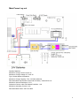
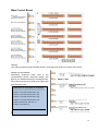
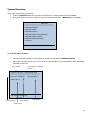
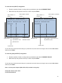
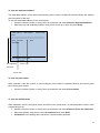
GST-IFP8 USER MANUAL
Notice
This instructions covered in this manual have been carefully checked for accuracy and are presumed
to be correct. However, the manufacturer assumes no responsibility for inaccuracies and reserves the
right to modify and revise this document without notice.
This manual covers the installation, programming and commission of the GST IFP8 Fire Alarm
Control Panels.
2
Contents Preface EN 54 Information ................................................................................................................. 4 Introduction ........................................................................................................................................ 5 Installation .......................................................................................................................................... 6 System Lay-out ................................................................................................................................... 8 Main Power Lay-out............................................................................................................................ 9 Main Control Board .......................................................................................................................... 10 Terminal Connection ........................................................................................................................ 10 Device Addressing ............................................................................................................................ 11 Control Panel and Indication ........................................................................................................... 13 Description of Controls .................................................................................................................... 14 Zone Indication Panel ...................................................................................................................... 15 System Commissioning ................................................................................................................... 16 Commission Mode .......................................................................................................................... 16 How to register a devices/Auto Learn ............................................................................................. 16 How to check duplicated address and device mismatch ................................................................. 17 How to modify the device address .................................................................................................. 17 How to modify the device sensitivity ............................................................................................... 18 System Programming ...................................................................................................................... 19 How to program the device detail.................................................................................................... 19 How to encode the text ................................................................................................................... 19 How to program the zone ................................................................................................................ 20 How to program the equation .......................................................................................................... 21 How to edit the device type ............................................................................................................. 22 System Browsing ............................................................................................................................. 23 To view the device detailed ............................................................................................................. 23 To view the zone (INPUT) assignment ............................................................................................ 24 To view the group (OUTPUT) assignment ...................................................................................... 24 To view the duplicated address ....................................................................................................... 25 To view the panel status .................................................................................................................. 25 To view the C&E Equation .............................................................................................................. 25 To view the system history .............................................................................................................. 26 SET-UP OPTION ................................................................................................................................ 26 To set-up the clock .......................................................................................................................... 26 To set-up the printer ........................................................................................................................ 26 To set-up the delay mode ................................................................................................................ 26 To set-up the local outputs .............................................................................................................. 27 SYSTEM OPERATION ....................................................................................................................... 28 Dependency Mode/ Pre-alarm ........................................................................................................ 28 Test Mode ....................................................................................................................................... 29 START/STOP OPTION ................................................................................................................... 29 DISABLE/ENABLE OPTION ........................................................................................................... 30 Maintenance ...................................................................................................................................... 31 System Menu .................................................................................................................................... 32 Lists of Device Type and Condition ................................................................................................ 36 Appendix 4 ...................................................................................................................................... 38 Operation Following an Alarm or Fault Condition ......................................................................... 39 3
Preface EN 54 Information
The GST IFP8 is an Intelligent Fire Alarm Control Panel complies with the latest requirement of EN
standard.
GST-IFP8 Intelligent Fire Alarm Control Panel (FACP) complies with the requirements of EN 54-2
1997 + A1: 2006 and EN 54-4 1997 + A1: 2002 + A2: 2006.
Option
Indication
Control
Outputs
Test
EN 54-2 Clause
Alarm counter
7.13
Fault signals from points
8.3
Delays to outputs
7.11
Dependencies on more than one alarm signal
7.12
Disablement of addressable points
9.5
Output to fire alarm devices
Control of fire alarm routing equipment
7.8
7.9
Output to fire protection equipment
7.10
Test condition
10
The power supply of GST-IFP8 FACP complies with EN 54-4 requirements.
Power supply from the main power source
Power supply from the standby power source (battery)
Charger
Faults
EN 54-4 Clause
5.1
5.2
5.3
5.4
In addition to functions required by EN54-2, the panel supports a number of ancillary functions that
are not required. These are outlined below:
Ancillary Function
Manual Section
SP-E32PK Printer
3.2.2
RS232/USB Output
2.3 & 3.2.2
GST852RP Repeater Panel
3.3.6
GstDef2.1 Defining Tool
3.4
Fire Alarm Output
4.4.3.3
RS485 Output
2.3 & 4.4.3.5
4
Introduction
The GST-IFP8 is an intelligent fire alarm control panel. Flush-mounted type housing it provides the perfect
solution for all medium to large system by utilizing advance GST Protocol.
The system is compatible with the complete range of GST Intelligent detectors, Sounders, Call Points, and
Interfaces, including intrinsically safe and gaseous extinguishing control. IFP8 is manufactured and
certified to EN54 parts 2 and 4 and to BS5839 Par 4.
8 x Loops (242) capacity (1936) addressable points
Maximum 10 Loops Standalone
Modular constructed for future expansion
40 x15 lines Colour Graphical LCD Display.
Up to 999 programmable zones and 140 zone indication
Auto Programming Day and Night Mode
Enable and Disable function
PAS and Acknowledge Function
Dirty Detector Reporting
Duplicate Address Checking
Walk Test Function with optional silent mode
Can edit device detailed and programmed
Programmable form PC or Panel
History record-999 fire incident only and 999 event capacity in non-volatile memory Fully simulation of
Cause and Effect
Advanced user friendly programming software including ‘Fuzzy Logic’.
Networked with all GST Intelligent Fire panels up to 99 Nodes, Optional Fiber Optic and LAN Network
Interface.
RS 485 mimic and repeater output up 64
RS 232-USB CRT interface, including GSTGMC graphic
Built in Fire Alarm, FPE, Fault and Alarm Router output
Panel Printer included
Built in Battery charger.
5
Installlation
Installatio
on of the pa
anel should be carried out by trained personnel only. The
e electronic componentss
inside th
he panel are
e vulnerable to damage by electros
static discha
arges. It is re
ecommende
ed to wear a
wrist stra
ap designed
d to preventt the buil-up
p of static charges
c
whithin the bod
dy, before handling
h
anyy
electronic circuit boa
ards.
Before unpacking an
nything, plea
ase review all
a the manual and draw
wing.
Open the
e IFP8 Conttrol Panel, unlock and prop the hing
ged door.
Locatting the hing
ge pin
Locating the
e hinge pin
Magnetic
Door Lock
Outer
or
Glass Doo
Back Box
Ke
ey Door Lockk
Main Doorr
6
Locate and placed the panel and marked the three holes for mounting.
7
System Lay-out
Main Control Board
Main Indication Board
Main Power
Board
AC Filter
Power Switch
AC/DC Power Converter
Zone Indication Board
Printer
8
Main Power Lay-out
Standby Batteries
Maximum Charge Current: 2A±0.1A
Maximum Charge Voltage: 27.3V±0.3V
Type: Sealed lead acid batteries
Maximum Charge Capacity: Two 12V/38Ah batteries
Recommended manufacturer and model of battery: Yuasa NP38-12I
Maximum Internal Resistance: 0.7Ω
Quiescent Current under Full-loaded Condition: 1.4A
Maximum Operating Current: 4.2A
Recommended Cable: GST fire cable
9
Main Control Board
Warning:
Use static precautions when handling boards, grounding wrist strap and contact with chassis.
Setting the card address
Numbering sequence, lower card is the
recommended lowest numerical setting. Set
dials on the additional board in ascending order.
Each card must be set at least one higher digit
than the lower card.
CARD SUM: 03 LOOP SUM: 04 SUM:0000
*****************************************
LOOP 1: Loop Card, Devices Sum: 000
LOOP 2: Loop Card, Devices Sum: 000
LOOP 3: Loop Card, Devices Sum: 000
LOOP 4: Loop Card, Devices Sum: 000
LOOP 5: Net Card-01, Net Sum: 01
LOOP 6: CRT CARD -01
Press F1 to print LOOP DEVICES info
Terminal Connection
10
Sample Wiring
Loop Parameter LOOP1~LOOP10
•
•
•
10 Loops+ Repeater Card
10 Loops + RS232 Card
8 Loops + RS232 Card +
Network Card
• 8 Loops + Network Card +
Repeater Card
• 6 Loops + RS 232 card +
Network Card + Repeater Card
Loop Address: 242
Output Voltage:
21-27Vdc
Output Current:
300mA
Wiring Topology:
Class A/Loop
Recommended Cable length: 1000
meters
Recommended Cable: GST Fire Cable
Loop protection: Optional loop isolator (C9503/4)
Device Addressing
The device address can be programmed manually through handheld programmer (P-9910B) or can
be changed in the control panel. The address of the device is recommended to be consecutive
number but not limited in order to have flexibility and should not be repeated. The address is stored in
the non-volatile memory chip inside the device
11
Description:
Output
Alarm
Routing
Output to
Sounder
Output to
FPE
Condition
Device
Number
Alarm
(Default)
Disable
CE Mode
Delay Time
Stop – via
Silence Button
Routing A
00000083
Immediate
Yes
No
Yes
No
Sounder A
00000082
Immediate
Yes
Yes
Yes
Yes
FPE A
00000081
Immediate
Yes
Yes
No
No
FEED BACK: Feedback signal input for alarm routing devices. It gives fault signal when connecting
line is shorted or opened.
REPEATER: Connecting with repeater panel.
FAULT OUTPUT: Fault relay is closed in normal condition, and it’s disconnected in fault condition.
12
Contro
ol Panel and Indiication
Descripttion of LED
Ds
Indicato
ors
Co
olour
Display::
Descriptio
on
This providess the message
e of the eventts and
system status..
When illumina
ated it indicate that
t
a FIRE hass been
detected in the
e protected loca
ation
How
w to clear
Attend
d the condition and perform the
e
panel reset
ect the condition
n that cause fault
Corre
and
automatically
y
clear
the
e
ation or perform a panel reset
indica
d the condition
n and press the
e
Attend
ACK button to turn the system to
o
n.
Pre-alarm verification
d the condition and press
Attend
EVAC
C button or nearest call point to
o
alarm
m the sounder or perform the
e
panel reset.
Exit the programming menu, and
d
matically clear th
he indication
autom
Repla
ace the battery
y or check the
e
conne
ections.
Turn –
–off and on the panel
Fire
RE
ED
Fault
YE
ELLOW
Pre-Alarrm
YE
ELLOW
Verify
YE
ELLOW
Maintenance
YE
ELLOW
Battery Fault
YE
ELLOW
System Fault
YE
ELLOW
Ground Fault
YE
ELLOW
Sounderr Fault
YE
ELLOW
Test Mode
YE
ELLOW
Sounderr
Disable
Disable
YE
ELLOW
When illumina
ated it indicates that part or all of the
sounder has been
b
disabled manually.
m
Enablle
the
device/s
d
and
d
autom
matically clear th
he indication
YE
ELLOW
Delay Mode
YE
ELLOW
When illumina
ated it indicates that part of the
e panel
has been disabled
When illumina
ated it indicattes that part of the
system output is block by dela
ayed.
Enablle
the
device/s
d
and
d
autom
matically clear th
he indication
Disab
ble the delay mo
ode
When illumina
ated it indicate th
hat a FAULT hass been
detected in the
e devices and alarm
a
system.
When illumina
ated it indicate that a PRE-A
ALARM
has been dete
ected in the spec
cified zone(s)
When illumina
ated it indicates
s that the ACK button
has been presssed and the alarm
a
sounders in the
system are delayed from alarm
ming.
When illumina
ated it indicates
s that the pane
el is in
programming mode.
m
Yellow. When
n illuminated it indicates tha
at the
battery has be
een failed.
When illumina
ated it indicate
es that the fau
ult has
occurred with the main proce
essor. It is sugg
gested
w not
to investigate the fault due to the panel will
able to attend the fires.
When illumina
ated it indicates that the panel or
o loop
wiring is groun
nded
When illumina
ated it indicates that a fault in th
he loop
sounders and panel sounder output.
When illumina
ated it indicates
s one or more zones
are in test mod
de.
Clearr the ground fault
Cance
el after correcte
ed the condition
n
that ccause sounder fa
ault.
Cance
el test when fin
nished
13
3
Power
GREEN
SILENCE
YELLOW
EVAC
RED
When illuminated it indicates the power supply is
present
When illuminated it indicates that the SILENCE
button has been pressed and.
N/A
Correct the alarm condition then
perform the panel rest. Note: If there
a new alarm occurs, the panel will
resound again.
When illuminated it indicates that the EVAC button
has been pressed
Description of Controls
SYSTEM SETUP: The System Set-up button is used to
access to the system menu. Each option in the menu
corresponds to one number button. This is accessible
under the manager password.
USER SETUP: The User Set-up button is used to access
to the user menu. Each option in the menu corresponds to
one number button. This is accessible under the operator
password.
Numerical and Alphabetic Keys (1, 2ABC, 3DEF, 4GHI,
5JKL, 6MNO, 7PQRS, 8TUV, 9WXYZ, 0, └┘, *): This button is
used to enter the data manually at the control panel.
RESET: Pressing the Reset button will clear all the events
and return the panel into a normal state.
MUTE: Pressing the Mute button will stop the internal
panel buzzer
SILENCE: Pressing the Silence button will stop panel
sounder output and loop sounders which programmed as
device type 12, 13, 14, 28, 29, and 30
EVAC: Pressing the EVAC button will start panel sounder
output and loop sounders which programmed as device
type 12, 13, 14, 28, 29, and 30
ACK: Pressing the ACK button will stop internal panel
buzzer and or acknowledging fire alarm under pre-alarm
condition.
CANCEL: Pressing the CANCEL button will cancel the
operation and shifted the display the message display to the highest priority.
ENTER: Pressing the Enter button will confirm entry.
,
,
,
: For turning pages or changing the input position.
14
Zone Indication Panel
Every FACP comes with two zone indication panels, appearance of which is shown in Fig. 3-4.
On the indication panel, each unit consists of two indicators and a label. The user can put the name of
device on the right of the indicators.
Indicators
Zone Fire
Colour
Red
Description
Zone Fault
Yellow
When illuminated it indicates that the zone is in a
fault condition
When illuminated it indicates that the zone is in a
fire condition
How to clear
Attend the alarm condition
and then reset the panel
Correct the fault condition
and then reset the panel
15
System Commissioning
Commission Mode
The control panel should be set to commissioning mode in order to have a full access in any programming menu of
the system.
To set the control panel in or out of commissioning mode:
•
Press the SYSTEM SETUP button, input the management password, no default password just press Enter
•
Then press number 3 button or using the cursor up and down and select 3 WORKING STATE SETUP the
press Enter
X
*WORKING STATE SET-UP*
*****************************************
1. COMMISSION
FIRE CONTROL PANEL IFP8
2. MONITORING
Panel Healthy
FAR: OK FPE: OK OTS: OK
01:13:19
FAR: OK FPE: OK OTS: OK
01:13:19
If there is an “X” displayed in the upper right corner of the screen, it is indicated that the panel is in commissioning
mode.
Note: After the completion of commissioning,
the control panel should be to set to “MONITORING MODE” and the “X” indicator will disappear.
How to register a devices/Auto Learn
The devices should be wired correctly and cards inserted properly and both are appropriately set the address
without any duplication. Starts the auto learn.
To set the control panel in registration mode:
•
Press the SYSTEM SETUP button, input the management password, no default password just press Enter
•
Then press number 4 button or using the cursor up and down and select 4 Commissioning then press
Enter
•
And then press number 1 or using the cursor up and down and select 1 Device Learn and press Enter
Registering active equipment
Please wait………..
16
FAR: OK FPE: OK OTS: OK
01:13:19
How to check duplicated address and device mismatch
To access the duplicated address check and device mismatched the system should be in DIGITAL mode (see the
System Initialization). The device mismatch will indicate if given a wrong device type on the actual installed
detector. This function is only allowed in smoke, heat and multi-sensor detector.
•
Press the SYSTEM SETUP button, input the management password, no default password just press Enter
•
Then press number 4 button or using the cursor up and down and select 4 Commissioning then press
Enter
•
And then press number 2 button or using the cursor up and down and select 2 Duplicated Address
Check the press Enter.
*DUPLICATED ADDRESS CHECK*
*DUPLICATED ADDRESS CHECK*
*****************************************
*****************************************
Duplicated Address Checking
Duplicated Address Check OK
Please wait……
Duplicated Address Sum: 001
Press (Cancel) to Exit!
FAR: OK FPE: OK OTS: OK
01:13:19
FAR: OK FPE: OK OTS: OK
1:13:19
If the system found the devices with duplicated address, the total number will be displayed. To find the exact
addresses and loop location press USER SETUP button and select 1 BROWSE then select 4 BROWSE
DUPLICATED ADDRESS
How to modify the device address
To access modify address the system should be in DIGITAL mode (see the System Initialization)
•
Press the SYSTEM SETUP button, input the management password, no default password just press Enter
•
Then press number 4 button or using the cursor up and down and select 4 Commissioning
•
And then press number 2 button or using the cursor up and down and select 3 MODIFY ADDRESS then
press Enter
•
Input the loop and the device address to be changed the press ENTER
•
Then input the new preferred address then press ENTER.
*MODIFY ADDRESS*
*****************************************
User Code: 00100103
Serial Number: 1013442E
New Address: 001
FAR: OK FPE: OK OTS: OK
01:13:19
17
How to modify the device sensitivity
To access modify sensitivity the system should be in DIGITAL mode (see the System Initialization)
•
Press the SYSTEM SETUP button, input the management password, no default password just press Enter
•
Then press number 4 button or using the cursor up and down and select 4 Commissioning
•
And then press number 2 button or using the cursor up and down and select 4 MODIFY DEVICE
SENSITIVITY
•
Input the loop and the device address to be changed the press ENTER.
Note: Be sure that the selected detector is programmed
*MODIFY DEVICE SENSITIVITY*
Loop: 01
Address (1-242): 001
*****************************************
*MODIFY DEVICE SENSITIVITY*
*****************************************
User Code: 00100103
Device Type: MULTISENSOR
Sensitivity: 2-sensitivity 2
New Sensitivity: 1
FAR: OK FPE: OK OTS: OK
01:13:19
The system verified the existing device sensitivity
FAR: OK FPE: OK OTS: OK
01:13:19
Then input the new sensitivity of the detector then press
ENTER.
18
System Programming
The control panel should be set to commissioning mode in order to have a full access in any programming menu of
the system.
How to program the device detail
To set the control panel in programming the device detail:
•
Press the SYSTEM SETUP button, input the management password, no default password just press Enter
•
Then press number 1 button or using the cursor up and down and select 1 PROGRAMMING
•
And then press number 1 button or using the cursor up and down and select 1 DEVICE SETUP
*DEVICE SETUP*
Loop: 01
Address (1-242): 001
*****************************************
*DEVICE SETUP*
Loop: 01
Address (1-242): 001
*****************************************
Zone (1-999)
: 001
Device Type
: 13 Sounder
Attribute (0-6)
: 01
Text (40 Byte)
:
Corridor
FAR: OK FPE: OK OTS: OK
•
01:13:19
FAR: OK FPE: OK OTS: OK
01:13:19
Input the loop and the device address to be changed the press ENTER
Device Parameters
Zone: Zone assignment
Device Type: Selection of device type.
Attribute: For output- 0-on/off ; 1-continoues
For detector- Sensitivity 1,2 or 3
Text: Device location text, character 40 max
How to encode the text
All the required letters and symbols are programmed in the system. The number keys have letter is
corresponding with the number button; each number has designated a capital or small letter.
Sample text encoding
Corridor
C - Press number 2 button then press 7 for capital C
o - Press number 6 button then press 4 for small letter o
r – Press number 7 button then press 4
r – Press number 7 button then press 4
i – Press number 4 button then press 4
d - Press number 3 button then press 2
o - Press number 6 button then press 4
r – Press number 7 button then press 4 for small letter r
19
How to program the zone
To set the control panel in programming the zone
•
Press the SYSTEM SETUP button, input the management password, no default password just press Enter
•
Then press number 1 button or using the cursor up and down and select 1 PROGRAMMING
•
And then press number 1 button or using the cursor up and down and select 2 ZONE SETUP
*ZONE SETUP*
*ZONE SETUP*
Zone (1-999): 001
Zone (1-999) : 001
*****************************************
*****************************************
Dependency Type (0-2)
: 1-Type A
Sounder Mode (0-1)
: 1 On C&E
Resound Mode
: 0-No Resound
: (0-1)
Zone LED (1-140): 001
Text (40 Byte)
:
Left Wing Second Floor
FAR: OK FPE: OK OTS: OK
•
01:13:19
FAR: OK FPE: OK OTS: OK
01:13:19
Input the 3 digits zone number then press ENTER
Zone Parameters
Dependency Type (0-2)
0-Off: Panel display Fire immediately- No Pre-alarm feature
1-Type A: Enable Pre-alarm feature- the system shall response to a second alarm from any device in the
same zone as the system alarm (Type A)
2-Type B: Enable Pre-alarm feature- the system shall response to a second alarm from any device in the
same or other zone as the system alarm (Type B)
Sounder Mode
0-Sound by Zone Fire: Alarm the sounder automatically if the fire is on the same zone
Ex: fire in zone 1, all the sounders in zone 1 will alarm
1-On E&C: Activation of Sounder through Equation
Resound Mode
0-No Resound: Sounder will not alarm if new fire from the other zone after being silenced
1-Resound by New Fire: Sounder will alarm if new fire from other zone after being silenced
Zone LED: 1-140 LED
Text: Zone location text, character 40 max
To encode the text use the alphanumerical buttons
20
How to program the equation
To set the control panel in programming the equation
•
Press the SYSTEM SETUP button, input the management password, no default password just press Enter
•
Then press the number 1 button or using the cursor up and down and select 6 C&E EQUATION SETUP
then press Enter.
*C&E EQUATION SETUP*
*CREATE C&E*
*****************************************
*****************************************
1. CREATE
C&E EQUATION Total
2. MODIFY
00100103 =001 0013 00
3. DELETE
4. INITIALIZATION
FAR: OK FPE: OK OTS: OK
01:13:19
FAR: OK FPE: OK OTS: OK
01:13:19
C&E Equation Parameters
Condition: INPUT DEVICES- 8 digits
Effect: OUTPUT DEVICES – 10 digits
Logic: AND Logic (x), OR Logic (+)
Fuzzy Logic: Asterisk (* value from 1-9)
Start the output: =
Stop the output: =X
999 242 99 = 999 242 99 99
Zone
Address
Device Type
Zone
Address
Device Type Delay Time
Condition
001 020 03
meaning Address 20 Optical smoke in Zone 1 (By Point)
001 *** 03
meaning At least 1(any address) Optical smoke in Zone 1 (By Zone)
*** *** 02
meaning At least 1(any address) Heat det. in the entire area (Global)
Effect:
XXX XXX 13 03 means sounder global alarm after 30 seconds (Global)
Sample:
001 *** 11 + 001 *** 03 + 001 *** 02 = 001*** 13 00, *** *** 13 06
21
How to edit the device type
To set the control panel in programming the device type
•
Press the SYSTEM SETUP button, input the management password, no default password just press Enter
•
Then press the number 1 button or using the cursor up and down and select 7 Device Type Setup then
press Enter.
No.
Device Type
No.
Device Type
No.
Device Type
No.
Device Type
00
UNDEFINED
25
USER DEFINED
50
USER DEFINED
75
Undefine
01
MULTISENSOR
26
USER DEFINED
51
USER DEFINED
76
Loop Short
02
HEAT DETECTOR
27
USER DEFINED
52
USER DEFINED
77
Loop Board
03
OPTICAL SMOKE
28
USER DEFINED
53
USER DEFINED
78
Delay Mode
04
USER DEFINED
29
USER DEFINED
54
USER DEFINED
79
Power Board
05
GAS DETECTOR
30
USER DEFINED
55
NET SounderA
80
CRT Board
06
BEAM DETECTOR
31
TROUBLE MONITOR
56
USER DEFINED
81
F.P.E.A
07
FLAME DETECTOR
32
PSU
57
USER DEFINED
82
SounderA
08
CONVENTIONAL P
33
USER DEFINED
58
USER DEFINED
83
ALARM ROUTINGA
09
USER DEFINED
34
USER DEFINED
59
USER DEFINED
84
Loop Flash Data
10
FLOW SWITCH
35
USER DEFINED
60
USER DEFINED
85
Undefine
36
USER DEFINED
61
USER DEFINED
86
Panel charger
37
USER DEFINED
62
USER DEFINED
87
BAT Resistance
11
MCP
(BG)
12
SOUNDER STOBE
13
SOUNDER
38
USER DEFINED
63
USER DEFINED
88
Undefine
14
FLASHER
39
Net Unit
64
USER DEFINED
89
Undefine
15
LIFT
40
Repeator
65
NET F.P.E.A
90
Undefine
16
FIRE DAMPER
41
ZONE VALVE
66
Undefine
91
Undefine
17
FIRE DOOR
42
FLOW SWITCH
67
Loop SW
92
Undefine
18
AHU
43
PRESSURE SWITCH
68
Loop Board
93
Undefine
19
EXTRACT FAN
44
USER DEFINED
69
CONTROL Panel
94
Undefine
20
BMS
45
USER DEFINED
70
ZoneDir Board
95
Undefine
21
USER DEFINED
46
USER DEFINED
71
AC Power
96
Undefine
22
USER DEFINED
47
USER DEFINED
72
Battery
97
Undefine
23
USER DEFINED
48
USER DEFINED
73
Keypad Board
98
Undefine
24
USER DEFINED
49
USER DEFINED
74
Ground.F
99
Undefine
•
The device type text description can be modified as user requirement through pressing F2 function key
•
Encode the text using alphanumerical keypad and confirmed by pressing Enter
22
System Browsing
To view the control panel programmed
•
Press the USER SETUP button, input the user password, no default password just press Enter
•
Then press number 1 button or using the cursor up and down and select 1 BROWSE the press Enter
*BROWSE*
*****************************************
1 BROWSE DEVICES
2 BROWSE ZONE
3 BROWSE GROUP
4 BROWSE DUPLICATED ADDRESS
5 BROWSE PANEL STATUS
6 BROWSE C&E EQUATIONS
7 HISTORY
FAR: OK FPE: OK OTS: OK
01:13:19
To view the device detailed
•
•
Press the number 1 button or using cursor up and down and select 1 BROWSE DEVICE
Select the loop using arrow cursor up or down and press Enter. To print selected the loop information
press F1 function key
Total number of registered
Loop Number
Devices
L00P01: Loop Card
DEVICE SUM: 0001
*****************************************
D001: 001 ZONE-001
MULTISENSOR
Training Room
FAR: OK FPE: OK OTS: OK
01 13 19
Device Address
Zone Number
Device Type
Location Text
23
To view the zone (INPUT) assignment
•
•
Press the number 2 button or using cursor up and down and select 2 BROWSE ZONE
Select the loop using arrow cursor up or down and press Enter.
Total Number of
Total number of INPUT
Total Number of
Total number of OUTPUT
Zones
devices
Groups
devices
ZONE SUM: 001
DEVICE SUM: 0023
GROUP SUM: 001
DEVICE SUM: 0023
*****************************************
*****************************************
ZONE: 001
GROUP: 001
Devices Sum: 0003
LED: 001
Second Floor
Second Floor
FAR: OK FPE: OK OTS: OK
Zone Number
Devices Sum: 0003
01:13:19
Total number of
Assigned LED
input devices in the
indication number
FAR: OK FPE: OK OTS: OK
Group Number
01:13:19
Total number of output devices in
the particular group
particular zone
Location Text
Location Text
To view the list of devices that are belong to a particular zone, select the zone using the arrow cursor UP or Down
and then press Enter.
To view the group (OUTPUT) assignment
•
•
Press the number 1 button or using cursor up and down and select 1 BROWSE GROUP
Select the loop using arrow cursor up or down and press Enter.
To view the list of devices that are belong to a particular zone, select the zone using the arrow cursor UP or Down
and then press Enter.
Note: 3 control panel outputs (FAR, FPE, OTS) included in the group:
Group 000 Devices sum: 0003
Control Panelseft Info
24
To view the duplicated address
The duplicated address check under commissioning menu must be enabled first before viewing the address
and the location of the loop.
To view the duplicated address on the control panel.
•
•
Press the number 2 button or using cursor up and down and select 4 Browse Duplicated Address
Select the loop with duplicated address using arrow cursor up or down and press Enter.
CARD SUM: 00
LOOP SUM:04
DEVICE SUM:
0023
*****************************************
D001: Zone-001
MCP
Corridor
FAR: OK FPE: OK OTS: OK
01 13 19
The duplicated
Device Type
addresses
Location Text
To view the panel status
When selected it view the number of card configured, total number of registered devices and control panel
power and system version.
•
Press the number 5 button or using cursor up and down and select 5 Panel Status
To view the C&E Equation
When selected it view the configured cause and effect in the control panel. To edit the equation refers to C&E
programming set-up.
•
•
•
Press the number 6 button or using cursor up and down and select 6 Browse Event and Command.
Select the equation using arrow cursor UP and Down then press Enter
Initialization is for deleting all the equations, required master password.
25
To view the system history
The history memory is divided in two parts FIRE HISTORY which stored only fire event and COMMON
HITORY for different types of system event except fire. Both have the 999 event capacity in non-volatile
memory
To view the events in the control panel:
•
•
•
Press the number 7 button or using cursor up and down and select HISTORY then Enter
Select the event using arrow cursor UP and Down then press Enter
To print the selected event press Enter
Note: Ensure that the printer is placed to ALL HISTORY.
SET-UP OPTION
To set-up the clock
This set-up allows the current date and time to be specified and entered into the panel memory.
• Press the USER SETUP button, input the user password, no default password just press Enter
• Then press number 2 button or using the arrow cursor up and down and select 2 CLOCK then press
Enter
To set-up the printer
This set-up allows to printer on or off condition
•
Press the USER SETUP button, input the user password, no default password just press Enter
•
Then press number 3 button or using the arrow cursor up and down and select 3 PRINTER SETUP then
press Enter
1. Disable – Printer in off condition
2. Only Fire – Automatic print in the event of fire
3. All History – Enable the printer.
To set-up the delay mode
This set-up allows the panel to delay the any output device type in the C&E Equation according to the
specified time.
NOTE: The panel operates in a delayed mode during the daytime only.
•
Press the USER SETUP button, input the user password, no default password just press Enter
•
Then press number 4 button or using the arrow cursor up and down and select 4 DELAY MODE SET-UP
then press Enter.
•
Select ENABLE or DISABLE then press Enter
26
To set-up the local outputs
This set-up allows the 3 on-board output circuits to delayed and placed in one or more alarm.
• Press the SYSTEM SETUP button, input the system password, no default password just press Enter
• Then press number 2 button or using the arrow cursor up and down and select 2 Local Output Setup then
press Enter.
•
Select the output circuits to set-up
Selection:
0 One Fire – Immediate start in any fire event
1 More Fire – Started if two or more fire events
2 On C&E – Start based on the configured equation.
Delay time - Works only in Output to Sounders (OTS) and Alarm Routing (FAR) and the ratio 1:10
seconds.
Note: Allows only if the DELAY MODE is set to enable
Output
Fire Alarm
Routing
Output to
Sounder
Output to
FPE
Condition
Device Number
Routing A
00000083
Sounder A
00000082
FPE A
00000081
27
SYSTEM OPERATION
Dependency Mode/ Pre-alarm
The signal from an automatic fire detection device selected for positive alarm sequence operation shall be
acknowledged at the fire alarm control unit by a trained personnel within given time of annunciation in order to
initiate the alarm investigation phase. If the signal is not acknowledged within the given time, notification signals in
accordance with the building evacuation or relocation plan and remote signals shall be automatically immediately
activated.
To program the pre-alarm of the panel in specified zones:
1. Ensure a zone(s) are programmed either Type A or Type B dependency to enable the mode (Check in
zone configuration)
2. Ensure that the DELAY MODE is placed on ENABLE
3. Set the Day/Night Mode:
To set-up the panel into Day mode:
• Press the SYSTEM SETUP button, input the management password, no default password just press Enter
• Then press the number 4 button or using the cursor up and down and select 4 DAY/NIGHT SETUP then
press Enter.
*DAY/NIGTH SETUP*
*****************************************
Please input the start time of day mode:
Default at 8:00 (hh:mm):
Please input the end time of day mode:
Default at 18:00 (hh:mm):
FAR: OK FPE: OK OTS: OK
•
01:13:19
Enter the time using the number buttons
4. Program the two stage timer which is built into a day mode.
To program the two stage timer:
• Press the USER SETUP button, input the user password, no default password just press Enter
• Then press number 5 button or using the arrow cursor up and down and select 4 ACKNOWLEDGE TIMER
then press Enter.
*ACKNOWLEDGE TIMER*
*****************************************
Please input the Pre-alarm ACK time:
Phase 1 (Default 30 S): [00] M-[30]S
Please input the Pre-alarm Verify time:
Phase 2 (Default 2 M): [02] M-[00]S
FAR: OK FPE: OK OTS: OK
•
01:13:19
Enter the time using the number buttons and press Enter
28
*Day Mode
Pre-alarm Window: programmable from 1 sec. to 30 min. A distinctive pre-alarm indication shall be displayed.
Alarm Verification window: programmable from 1 sec. to 30 min.
*Night Mode (Default setting)
Pre-alarm Window: preprogrammed 30 min. Auto-reset the Alarm in the Panel after 30 min (Type A)
Pre-alarm Window: preprogrammed 5 min. Auto-reset the Alarm in the Panel after 5 min (Type B)
The system shall response to a second alarm from any device in the same zone as the system alarm (Type A)
The system shall response to a second alarm from any device in the same or different zone as the system alarm
(Type B)
The manual call points are excluded in the pre-alarm mode.
Test Mode
The control panel is in test status and indicates the zone under test condition.
To set the panel into test mode
• Press the USER SETUP button, input the user password, no default password just press Enter
• Then press number 6 button or using the arrow cursor up and down and select 4 TEST SETUP then press
Enter.
Selection:
1 LED Buzzer test – When selected the panel ON all the LED and start the buzzer.
2 Local Output Test – Is for testing the 3 on-board output circuits. When selected, it will indicate TEST
message and alarm the output within 15 seconds.
3 Set-up Test Zone – Possible one or more zones can be set to test condition with or without loop sounder
assigned to a zone within 10 seconds.
4 Cancel Test Zone – canceled by manual operation.
START/STOP OPTION
Any or group of device registered onto the control panel can start by manual operation by entering the zone
number, address and device type.
To set the panel into test mode
• Press the USER SETUP button, input the user password, no default password just press Enter
• Then press number 7 button or using the arrow cursor up and down and select 7 STOP/START DEVICE
then press Enter.
29
DISABLE/ENABLE OPTION
Any or group of device registered onto the control panel can disable by manual operation by entering the
zone number, address and device type.
To set the panel into test mode
• Press the USER SETUP button, input the user password, no default password just press Enter
• Then press number 8 button or using the arrow cursor up and down and select 8 DISABLE/ENABLE then
press Enter.
30
Maintenance
The FACP shall only be repaired by specially trained GST technical service personnel. Please
disconnect the power before repair!
Warning: The key to the FACP shall be kept by specially assigned maintenance personnel!
Replacing the Battery
Type of battery: Sealed lead-acid battery
Recommended period for replacing the battery: 5 years (25Ԩ)
Recommended manufacturer and model: Yuasa/NP38-12I
Disposal of used batteries: Please properly dispose the used batteries according to your local rules
and regulations.
NOTE: RISK OF EXPLOSION IF BATTERY IS REPLACED BY AN INCORRECT TYPE.
Replace of Fuse
Position
Mark
Rating
Power filter F7.820.323
F1
2A delay
Troubleshooter
No. Problems
Possible Causes
Solutions
1
No indication on Power is abnormal
Check and replace low-voltage
the panel or
Loose connection with
switch power.
abnormal
switchboard.
Check the connection to display
indication
board.
2
Display “AC
No AC power
Check and connect AC wire.
Fault” after
power-up.
3
Display “Battery Loose connection with
Open the power box and check
Fault” after
battery.
relative parts.
power-up.
Battery discharged or
Power up for more than eight
damaged.
hours with the AC power supply, if
the fault still exists, replace the
batteries.
4
Unable to
Bus wrong or loose
Check the loop
register loop
connection
equipment
5
Unable to
Wrong or loose connection Check power supply to repeaters
register repeater of communication cables
and communication wires
panels
6
Cannot print
Print mode is disabled.
Enable the print mode.
Loose connection with
Check and connect the printer
printer.
well.
Printer damaged
Replace the printer.
7
Equipment fault Equipment disconnected.
Check connection
Equipment damaged.
Replace equipment
8
Loop fault
Loop is shorted
Check the loop and repair.
9
Clock or memory External interference.
Check if the FACP is properly
fault.
Corresponding parts are
earthed.
aging.
Inform our technical service
31
System Menu
System Setup
1 PROGRAMMING
1 Point-Setup: loop 01 point (1-242)
Zone (1-999):
Device Type:
Attribute (0-6):
Text (40 byte):
2 Zone Setup: (I-999) (Select the zone)
Dependency type (0-2)
0 – Off
1 – Type A
2 – Type B
Sounder Mode (0-1)
0 – Sound by Zone Fire
1 – On E&C
Resound Mode (0-1)
0– No Resound
1 – Resound by New Fire
Zone LED (1-140): Text (40byte)
3 Communication Setup
1. Monitor interface (interface card RS232)
Please input loop number: (1:10)
Please input panel address: (1-32)
2 Network Interface
Please Input loop number: (1-10)
Please Input panel address (1-64)
4 Day / Night time Set-up
Please Input start time of day mode (08:00) default
Please Input the end time of day mode (18:00)
5 Modify Password
1. Operator Password
2. Manage Password
6 C&E Equation Set-up
1. Create
2. Modify
3. Delete (one by one)
4. Initialization (To clear all the equation)
7 Device Type Set-Up
(see table 1)
32
2. LOCAL OUTPUT SETUP
Sounder A Mode (0-2)
0-one fire
1-more fire
2-On C&E
FPE A Mode (0-2)
0-one fire
1-more fire
2-On C&E
Alarm Routing A mode (0-2)
0-one fire
1-more fire
2-On C&E
Delay Time: 00 (note: ratio 1:10)
3. WORKING STATE SET-UP
1. Commission (note:“X” upper right corner)
2. Monitoring
4. Commissioning
1. Device Learn (To registered devices)
2. Duplicated Address Check
3. Modify Address (To change the device address)
Select the loop and device address
User Code: 00100106 (zone,address,device type)
Serial Number: device serial number
New Address: Enter new address
4. Modify Device Sensitivity (To change the device sensitivity)
Select the loop and device address
User Code: 00100106 (zone,address,device type)
Serial Number: device serial number
Sensitivity: existing sensitivity
New Sensitivity: Enter new sensitivity (1-3)
5. Commission in Analog Mode (Command 0)
Normal Status: Range 450 to 650
Alarm Status:
Range from 900 to 1200
Fault Status:
Range from 1 to 120
6. Commission in Digital Mode
7. System Initialization.
Press 1 Initialize detector to digital mode
Press 2 Initialize detector to analog mode
Press 3 To initialize the system
Press 4 To disable battery resistance,
Press 5 To hide sounder alert item
33
User Setup
1 BROWSE
1 Browse Devices: View the number of devices per loop and detailed provided with
each device
2 Browse Zone: View the total number of Input devices per zone
3 Browse Group: View the total number of Output devices per group (Zone)
4 Browse Duplicated Address : View the repeated address in a loop
5 Browse Panel Status: View the panel configuration and version
6 Browse Event and Command: C&E or Sequence of operation detailed
7 History:
1 Fire History
2 Common History
3 Initialization
2 CLOCK
3 PRINTER SETUP
1 Disable
2 Only Fire : Automatic print on fire event
3 All History: Pressing PRINT when viewing history records can print out
the messages being viewed
4 DELAY MODE SETUP
1 Disable
2 Enable
5 ACKNOWLEDGE TIMER
Phase 1 (30 seconds default)
Phase 2 (2 minutes default)
6 TEST SETUP
1 LED Buzzer Test
2 Local Output Test
1 Output to Sounder Test (OTS)
2 Output to F.P.E. (FPE)
3 Alarm Routing Test (FAR)
3 Setup Test Zone
Input test zone : (1-999)
Input test mode : (0-1)
0-Without sounder
1-With sounder
4 Cancel Test Zone
1 Cancel One Test Zone
2 Cancel All Test Zone
34
7 START/STOP DEVICE
1 Start Device
2 Stop Device
By device code- Zone, address, device type
8 DISABLE/ENABLE
1 Dis/Enable Devices – By Code
1 Disable Device
2 Enable Device
2 Dis/Enable Device – By Address
1 Disable Device
2 Enable Device
2 Dis/Enable Zone
1 Disable Zone
2 Enable Zone
1 Disable/Enable Sounder
1 Disable Sounder
2 Enable Sounder
35
Lists of Device Type and Condition
DEVICE TYPE Undefine MULTISENSOR HEAT DETECTOR OPTICAL SMOKE USER DEFINED GAS DETECTOR BEAM DETECTOR FLAME DETECTOR CONVENTIONAL P USER DEFINED FLOW SWITCH MCP (BG) SOUNDER STOBE SOUNDER FLASHER LIFT FIRE DAMPER FIRE DOOR AHU EXTRACT FAN BMS USER DEFINED USER DEFINED USER DEFINED USER DEFINED USER DEFINED USER DEFINED USER DEFINED USER DEFINED USER DEFINED USER DEFINED TROUBLE MONITOR PSU USER DEFINED USER DEFINED USER DEFINED USER DEFINED USER DEFINED DEVICE NUMBER 0 1 2 3 4 5 6 7 8 9 10 11 12 13 14 15 16 17 18 19 20 21 22 23 24 25 26 27 28 29 30 31 32 33 34 35 36 37 RELAY Latching Latching Latching Latching Latching Latching CONDITON FIRE ACTION FAULT 36
USER DEFINED Net Unit Repeator ZONE VALVE FLOW SWITCH PRESSURE SWITCH USER DEFINED USER DEFINED USER DEFINED USER DEFINED USER DEFINED USER DEFINED USER DEFINED USER DEFINED USER DEFINED USER DEFINED USER DEFINED NET SounderA USER DEFINED USER DEFINED USER DEFINED USER DEFINED USER DEFINED USER DEFINED USER DEFINED USER DEFINED USER DEFINED NET F.P.E.A Undefine Loop SW Loop Board CONTROL Panel ZoneDir Board AC Power Battery Keypad Board Ground.F Undefine Loop Short Loop Board Delay Mode Power Board CRT Board F.P.E.A SounderA 38 39 40 41 42 43 44 45 46 47 48 49 50 51 52 53 54 55 56 57 58 59 60 61 62 63 64 65 66 67 68 69 70 71 72 73 74 75 76 77 78 79 80 81 82 SUPERVISORY ACTION PANEL 37
ALARM ROUTINGA Loop Flash Data Undefine Panel charger BAT Resistance Undefine Undefine Undefine Undefine Undefine Undefine Undefine Undefine Undefine Undefine Undefine Undefine 83 84 85 86 87 88 89 90 91 92 93 94 95 96 97 98 99 Appendix 4: Index of Information Required by EN54-2
EN54-2 Clause 12.2
Chapters or sections
in this manual
General description of the equipment
Chapter 1
Optional functions with requirements of EN542, functions relating to EN54-4, ancillary
functions not required by EN54-2
Preface
Power requirement for recommended operation
Section 2.1, 2.2
Maximum capacity per detection circuit
Section 2.4
Maximum capacity per FACP
Chapter 1
Electrical ratings for inputs and outputs
Section 2.5
Communication parameters on transmission
paths
Section 2.4, 2.5
Fuse ratings
Section 8.2
12.2.1.c
Installation information
Section 4.1, 4.2, 4.3,
4.4
12.2.1.d
Configuring and commissioning instructions
Section 4.5, 4.6, 4.7
12.2.1.e
Operating instructions
Chapter 6
12.2.1.f
Maintenance information
Chapter 8
12.2.1.a
12.2.1.b
38
Operation Following an Alarm or Fault Condition
FIRE
Alarm Tone and Red LED
Fire
Sum:001
001: 13 Jan
10:01
Zone 001
Sum001/002 [√]
Second Floor
→Press [Enter] to view details
→Press [L/R Scroll] to switch inf. type
Last Fire:
13Jan
10:01
Zone001
[√]
Second Floor
FAR:ON
FPE:ON
OTS:ON
10:20:01
1. Open the door. LCD screen displays: The first, and in multiple alarm condition also the last fire,
time and zone location. Fire LED turn on steady and corresponding zone indication.
2. Press ENTER to view the device loop, address, device type and location
3. To view all fire events press key ▲and▼ (Up and Down cursor to scroll)
Fire
Zone:001
001: 13 Jan
10:01
Sum:001
L01D002
MCP
(BG)
Corridor Left Wing
→Press [F1] to disable device
→Press [L/R Scroll] to switch inf. type
Last Fire:
13Jan
10:01
Zone001[√]
Second Floor
FAR:ON
FPE:ON
OTS:ON
10:20:01
Silencing the panel and signal
1. Silence the control panel
Press the ‘MUTE” Button and the MUTE LED turn on steady
2. Silencing the sounder signal
Press the “Silence” Button and the corresponding key LED illuminates
Resetting the system
1. When the alarm condition has been cleared, restore and replace all affected devices in
accordance with the details provided with each device.
2. Reset the system
In fire mode. Press ‘RESET” key.
Display show “Please Input Password: ___” input After reset the display should shows “ System
Running”
39
FAULT
Alarm Tone and Yellow LED
Fault
Sum:001
001: 13 Jan
10:01
Zone 001
Sum001/002 [√]
Second Floor
→Press [Enter] to view details
FAR:OK
FPE:OK
OTS:OK
10:20:01
1. Open the door. LCD screen displays: The first, and in multiple alarm condition also the last fault, time
and zone location. Fault LED turn on steady and corresponding zone indication.
2. Silence the panel, press the “MUTE” and the MUTE LED turn on steady.
3. Press ENTER to view the device loop, address, device type and location
4. To view all fault events press key ▲and▼ (Up and Down cursor to scroll)
Fault
Sum:001
001: 13 Jan
10:01
L01D003
Multi Sensor
NRT Training Room
→Press [F1] to disable device
FAR:OK
FPE:OK
OTS:OK
10:20:01
Check the fault, restore or replace the defective device. Isolate the fault during analysis if
necessary.
Disable the device
1. Press “F1 “then Input Password: ___”.
2. Confirm by pressing “Enter” and the Disable yellow LED turn on steady.
Enable the device
1.Press ► or◄, Then F1 and follow the display instruction
2.Disable LED turns off once it is confirmed
Resetting the system
1. On Fault mode. Press ‘RESET” key
2. Display show “Enter Password: ___” input the code. Press “Enter”
Note: Disable can be rested only by Enable operation
The display show “Panel Healthy With Disable”
40
Global System Technology PLC
Lion Court, Staunton Harold Hall,
Melbourne Road, Ashby de la Zouch,
Leicestershire,
England LE65 1RT
Tel: +44 1283 225 478
Fax: +44 1283 220 690
Email: [email protected]
www.gst.uk.com
Global System Technology PLC
PO Box 17998 Unit ZA04 JEBEL ALI Free Zone,
Dubai, UAE
Tel: +971 (0) 4 8833050
Fax: +971 (0) 4 8833053
Email: [email protected]
www.gst.uk.com
41