1
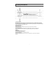
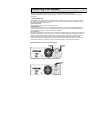
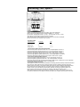
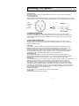
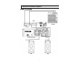
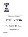
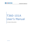
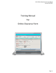
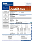
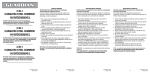
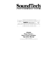
PS3402 Power Source Stereo Power Amplifier Operation Manual COPYRIGHT 2001 SOUNDTECH UNAUTHORIZED REPRODUCTION IS A VIOLATION OF APPLICABLE COPYRIGHT LAWS PS3402 Power Source 2 Channel Digital Power Amplifier Table Of Contents 1 2 3 4 5 6 7 8 Introduction......................................................................................... Important Safety Instructions............................................................. Warranty Information.......................................................................... Panel Description............................................................................... Connecting Your System................................................................... System Hookup Diagram................................................................... Block Diagram.................................................................................... Specifications...................................................................................... 2 3 4 5-6 7-10 11 12 13 I Introduction The SoundTech PS3402 Power Source is a high quality power amplifier featuring state-of-the art performance designed for professional sound reinforcement and installation use. The PS3402 is a stereo digital power amplifier that can also be used for high level monophonic performance by making use of the bridge mode. A distinguishing feature of the Power Source Series Amplifiers is the Digital switching power supply that makes high powered performance with extremely low weight possible. The PS3402 Power Source features oversized high efficient heat sinks in a wind tunnel cooling system with a variable speed fan for trouble free operation under the most adverse conditions. In addition, PS3402 Power Source has attractive front panel controls with a full complement of LED’s to monitor functions and performance level conditions. While providing powerful, accurate and reliable performance along with outstanding value, your SoundTech PS3402 Power Source power amplifier has been designed for many years of dependable service. Please take the time to read this manual before operation so that you fully understand the features and correct use of this exceptional product. 2 II Important Safety Instructions 1. Read Instructions- All the safety and operating instructions should be read before the amplifier is operated. 2. Retain Instructions- The safety and operating instructions should be retained for future reference. 3. Heed Warnings- All warnings on this amplifier and in the operating instructions should be adhered to. 4. Follow Instructions- All instructions should be followed. 5. Water and Moisture- This amplifier should not be used near water- for example, near a bathtub, sink, laundry tub, in a wet basement, near a swimming pool, etc. 6. Heat- This amplifier should be situated away from heat sources such as radiators, heat registers, stoves, or other appliances that produce heat. 7. Power Sources- This amplifier should be connected to a power supply only of the type described in the operating instructions or as marked on the amplifier. If you are not sure of the type of power supply to your home, consult an electrician or local power company. 8. Polarization- If the amplifier is equipped with a polarized alternating-current line plug (a plug having one blade wider than the other), this plug will fit into the power outlet only one way. This is a safety feature. if you are unable to insert the plug fully into the outlet, try reversing the plug. If the plug should still fail to fit, contact your electrician to replace your obsolete outlet. Do not defeat the safety purpose of the polarized plug. 9. Grounding- If the amplifier is equipped with a 3-wire grounding-type plug, a plug having a third (grounding) pin, this plug will only fit into a grounding-type power outlet. This is safety feature. If you are unable to insert the plug into the outlet, contact your electrician to replace your obsolete outlet. Do not defeat the safety purpose of the grounding-type plug. 10. Power Cord Protection- Power supply cords should be routed so that they are not likely to be walked on or pinched by items placed upon or against them, paying particular attention to cords at plugs, convenience receptacles, and the point where they exit from the amplifier. 11. Damage Requiring Service- Unplug this amplifier from the wall outlet and refer servicing to qualified service personnel under the following conditions: a. When the power-supply cord or plug is damaged. b. If liquid has been spilled, or objects have fallen into the amplifier. c. If the amplifier has been exposed to rain or water. d. If the amplifier does not operate normally by following the operating Instructions. Adjust only those controls that are covered by the operating instructions as an improper adjustment of other controls may result in damage and will often require extensive work by a qualified technician to restore the amplifier to its normal operation. e. If the amplifier has been dropped or the cabinet has been damaged. f. When the amplifier exhibits a distinct change in performance-this indicates a need for service. 12. Servicing- Do not attempt to service this amplifier yourself as opening or removing covers may expose you to dangerous voltage or other hazards. Refer all servicing to qualified service personnel. 3 III Warranty Information UNPACKING As a part of our system of quality control, every SoundTech product is carefully inspected before leaving the factory to insure flawless appearance. After unpacking, please inspect for any physical damage. Save the shipping carton and all packing materials, as they were carefully designed to reduce the possibility of transportation damage should the unit again require packing and shipping. In the event that damage has occurred, immediately notify our dealer so that a written claim to cover the damage can be initiated with the carrier. The right to any claim against a public carrier can be forfeited if the carrier is not promptly notified and if the shipping carton and packing materials are not available for inspection by the carrier. Save all packing materials until the claim has been settled. SOUNDTECH LIMITED 5 YEAR WARRANTY SoundTech electronics are warranted to be free from defects in materials and workmanship under normal use for a period of 5 years from date of original purchase. During that period, SoundTech will at its option, repair or replace materials at no charge if product has been delivered to SoundTech by a SoundTech dealer or SoundTech Service Center together with the original sales receipt or other proof of purchase. Warranty excludes fuses, exterior finish, normal wear, failure due to abuse, or operation outside of specified ratings. Warranty applies to original purchaser only. This warranty gives you specific rights which vary from state to state. FOR YOUR RECORDS All of us at SoundTech thank you for your expression of confidence in SoundTech products. The unit you have purchased is protected by a limited 5 year warranty. To establish the warranty, be sure to fill out and mail the warranty card attached to your product. SoundTech Customer Service Department 444 East Courtland Street Mundelein, IL 60060 847-949-0444 extension 230 847-949-8444 fax For more information about warranty repair, please contact: For you own protection, fill out the information below for you own records. Model Number Serial Number Dealer Date Of Purchase Salesman Phone Other Information: 4 IV Panel Descriptions FRONT PANEL 1. Power On/Off Switch Before applying power, check all connections and turn down the gain control. The "Soft Start" sequence starts with the POWER indicator LED at half brightness. A couple seconds later the fan starts and the amplifier cycles through one second of protective muting, indicated by the CLIP and protect LED’s glowing bright red. The POWER indicator then changes to full brightness and the amplifier is ready. 2. Power Indicator LED Illuminates when the power is on. 3. Peak Indicator LED Indicates that channel of the amplifier is being driven past normal power limits into distortion. 4. Protect Indicator LED If protect conditions should occur, such as a short in a speaker cable or connector or excessively high operating temperatures, this LED will light and the amplifier will stop operation until the condition is corrected. 5. Signal LED Indicates that a signal is present at the input. 6. Mono/Bridge Mode Indicator LED Shows when channels 1&2 are in the bridged mono mode. 7. Input Level Attenuator Establishes the required input level for each channel. In the bridge mode, only the channel 1 attenuator is functional. 5 Panel Descriptions REAR PANEL 8. Speakon Connector Speaker Outputs Separate NL4 connectors for CH. 1 and CH. 2 stereo outputs. Note: These connectors are in parallel with the binding post connectors. Care should be taken when attempting to use both types of connector simultaneously. 9. Binding Post Speaker Outputs Connectors are 5-way binding posts for maximum versatility. Use a standard banana plug or bare wire. 10. XLR and ¼” Inputs Low impedance, balanced inputs accept a male XLR connector or a ¼” TRS phone jack. Unbalanced inputs accept a mono ¼” phone plug. Note: The ¼” input accepts either tip/ring/sleeve or tip/sleeve phone connectors. 11. Bridge Mode Switch Bridges the outputs as indicated. Run this in either bridged mono or in stereo depending on the position of the switch. 12. Clip Limiter When an audio signal drives an amp's output circuit beyond its power capability, its clips, flattening the peaks of the waveform. A clip limiter detects this and quickly reduces the gain to minimize the amount of overdrive. The PS3402 has a clip limiter built in and you can switch it on or off as shown at the rear panel. 13. Input Filter (Low Cut Filter) The switchable low-frequency (LF) filter rolls off signals below either 30Hz or 50Hz. This improves performance by eliminating subsonic cone motions making more power available for the speaker rated frequency range. The filters frequency setting for both channels is controlled by the 30Hz/50Hz slide switch. 14. AC Power Cord. This heavy duty power cord uses a 20 amp connector where one blade is perpendicular instead of parallel to the other blade. This is a safety feature to prevent you from plugging into a circuit less than 20 amps. The outlet receptacle will have one T shaped blade insert that will accept both types of connectors. If you do not have this type of receptacle, please contact your local electrician for an upgrade. 15. Cooling Air Port. Do not obstruct air flow to this opening. 6 V Connecting Your System A. MOUNTING The PS3402 Power Source is designed for standard 19” rack mounting. In addition, the amplifier is provided with sturdy no-skid rubber feet for secure table top or stacked operation. When rack mounting one or more amplifiers or when mounting in combination with other equipment, be sure to allow adequate front and rear ventilation to avoid possible heat related damage to your PS3402 Power Source or other rack mounted items. B. OPERATING PRECAUTIONS Your SoundTech PS3402 Power Source power amplifier is well protected from any external faults. However, we recommend following these common sense precautions: 1. Safety Instructions Read and follow all of the safety warnings in this manual.. Do not expose the PS3402Power Source to water or other liquids. Always unplug the unit if water is present. Failure to do so can result in injury or death from electric shock. 2. Grounding Your power amplifier is supplied with a three conductor, grounded power cord and plug. Connect the unit only to a properly grounded mains outlet. Do not use a ground lift adapter or otherwise attempt to defeat the ground on the plug. Failure to properly ground the unit can result in damage to the amplifier or other equipment connected to it and represents a dangerous safety hazard. 3. Line Voltage Operate from AC mains not more than 5% above or below the specified line voltage. Failure to comply may invalidate your warranty. 4. Pre-Connection Caution Always switch off the power and set all the level controls to minimum before making any connections. This will eliminate any chance of unexpected, loud audio transients that could damage your speaker systems. C. STEREO OPERATION Each channel provides a separate and discrete signal at the speaker outputs according to the signal received at the inputs. The PS3402 Power Source has two channels for stereo operation. Follow these steps to use the amplifier in this manner: 1. Set Mono/Bridge switch Set the mono/bridge switch on the rear panel to the stereo position. When the power is on, the mono/bridge LED on the front panel will not light. If the LED illuminates, you have the switch in the wrong position. Change the position of the switch before continuing. 2. Input Connections With the power off, connect your input source lines to channels 1 and 2 on the PS3402. 3. Speaker Outputs Connect speaker systems to speaker outputs as shown in figure 3. The total speaker load for each channel must be at least 2 Ohms. The amplifier will not operate at load conditions lower than 2 Ohms per channel. 4. Level Controls With all level controls set to 0, switch the power on. Apply a nominal signal to the inputs. The level of the input signal should be about as high as you will ever need it to be. This way, it will be as far above the amplifier's noise floor as possible, ensuring an excellent performance signal to noise ratio. Adjust the input level controls for each channel to achieve the desired maximum listening level or until the clip LED’s flash momentarily during program peaks, whichever is lowest. Having set the levels in this manner will render a clean signal at any level as long as the clip LED’s are not constantly on. Remember, when the clip LED’s start to light you are within 3dB of clipping. 7 Connecting Your System D. MONO/BRIDGE OPERATION This method of operation bridges the outputs and can be used with 4 Ohm or higher loads only. Bridging the PS3402 converts the amp to a monophonic or single channel amplifier, providing 3400 watts into a 4 Ohm load. 1. Set Mono/Bridge switch Set the switch on the rear panel to the mono/bridge position. When the power is on, the mono/bridge LED on the front panel will light. If the LED does not illuminate, you have the mono/bridge switch in the wrong position. Change the position of the switch before continuing. 2. Input Connections With the power off, connect your input source to channel 1. 3. Speaker Outputs Connect speaker systems to the top 2, red binding post outputs only (see figure 4). The total speaker load must be at least 4 Ohms or above. If you try to operate at less than 4 Ohms in the bridge mode, the amplifier will go into protect mode and stop operation until you correct the load condition. 4. Level Controls With all level controls set to 0, switch the power on. Apply a nominal signal to the inputs. The level of the input signal should be about as high as you will ever need it to be. This way, it will be as far above the amplifier's noise floor as possible, ensuring as excellent performance signal to noise ratio. Adjust the input level control for channel 1 to achieve the desired maximum listening level or until the clip LED’s flash momentarily during program peaks, whichever is lowest. Having set the levels in this manner will render a clean signal at any level as long as the clip LED’s are not constantly on. Remember, when the clip LED’s start to light, you are within 3 dB of clipping. FIGURE 3. Speaker Connection For Stereo Operation FIGURE 4. Speaker Connection For Mono/Bridge Operation 8 Connecting Your System E. OUTPUT CONNECTIONS 1. Speakon Output Connectors Speakon connectors are purpose-built for low voltage, high current applications. Each connector incorporates two pair of conductors, labeled 1+, 1-, 2+ and 2-. By convention, single signals are sent on 1+ and 1-. The second pair, 2+ and 2-, is used only if there is a second unique signal present at the connector. When attaching NL4FC mating connectors, be sure to insert the connector to its full depth, then turn the connector 45° clockwise to lock it in place. Connection Table Output Function Connector Pins Left (CH 1) A 1+, 1- Right (CH 2) B 1+, 1- Bridged Mono A and B 1+, 1+ a. Connection for Stereo (Two-Channel) Operation Connect the left speaker's positive terminal to the 1+ pin of output Speakon connector A. Connect the left speaker's negative terminal to the 1- pin of output Speakon connector A. Note that the total speaker load impedance on this output must be 2 Ohms or greater. Connect the right speaker's positive terminal to the 1+ pin of output Speakon connector B. Connect the right speaker's negative terminal to the 1- pin of output Speakon connector B. Note that the total speaker load impedance on this output must be 2 Ohms or greater. b. Connection For Bridged Mono Operation. Connect the speaker's positive terminal to the 1+ pin of output Speakon connector A. Connect the speaker's negative terminal to the 1+ pin of output Speakon connector B. Note that the total speaker load impedance on this output must be 4 Ohms or greater since, in this configuration, each amplifier output is presented with half the mono bridged load 2. Binding Post Output Connectors These speaker connections are dual banana MDP/bare wire binding posts that will accept a standard dual banana plug or bare wire. Either method provides a safe and reliable connection capable of transferring high power signals if properly connected. To avoid ANY possible shock hazard, the power amplifier should be disconnected from the AC power source before making any connections. When connecting your speakers using either method, be sure to pay close attention to proper polarity. Although connecting your speaker system out of phase using the wrong polarity will not damage your speakers, it will affect the quality of sound. When using bare wire connections, be sure that your connections are "clean." If any strands of wire from one connector are allowed to touch the adjacent connector, damage to your amplifier and sound system could occur. 9 Connecting Your System F. INPUT CONNECTIONS 1. XLR Input Jacks Electronically balanced inputs accept a standard XLR male connector. Pin 1=ground, Pin 2=hot or positive(+). Pin 3=cold or negative(-). 2. 1/4'' Phone Input Jacks Accepts a balanced or unbalanced line level signal. The balanced line uses a tip/ring/sleeve phone connector. The tip is positive, the ring negative and the sleeve is ground. This input will also accept an unbalanced tip/sleeve connector. G. POWER REQUIREMENTS Your SoundTech PS3402 Power Source is pre-wired at the factory for the correct line voltage (120V or 220-240V) and is furnished with the appropriate power cord and fuse. If fuse replacement is necessary, always use a fuse with the exact type and rating as specified on the specifications page of this manual or as indicated on the unit itself. H. FRONT PANEL INDICATORS The front panel of the PS3402 Power Source has several indicators to alert you to the status of various operating conditions. Knowing what these indicator LED’s are telling you will help you to use your SoundTech amplifier to it’s fullest potential. 1. Peak LED A clip LED for each channel indicates that your signal level is so strong that there is distortion at the output of that channel. While it is normal for the clip LED to flash during program peaks, the LED should not remain constantly lit during operation. If it does, most likely you will hear the results in the form of distortion that can be damaging to your speaker systems. In this case, reduce the signal level by lowering the input level control for the channel that is clipping or reduce the level at the source. Note that when using the amplifier in the bridge mode, both clip LED’s of the bridged channels will operate simultaneously. 2. Mono/Bridge LED The mono/bridge LED will light when you have set the rear panel switch to the mono/bridge position for bridged operation. Always make sure that this switch is in the correct position and that all speaker connections have been made correctly for the mode of operation you wish to use before powering up the amplifier. 3. Protect LED The protect LED indicates that there is a problem either in the amplifier's external connections, load or temperature conditions or its internal functions. If one of these situations occur, the amplifier senses the problem and automatically switches into its "protect mode." The protect LED will light to warn you of the trouble and the amplifier will stop working. If this happens, switch off the amplifier and check connections, cables and speaker loads. Make sure there is adequate ventilation to the amplifier. If you feel that you have been able to correct the fault condition that caused the amplifier to go into the protect mode, restart the amplifier. If the protect LED remains lit when attempting to resume amplifier operation, do not use the amplifier. Refer the amplifier to an authorized SoundTech service facility or contact your dealer for help. 4. Power Indicator LED The power indicator LED indicates that the power switch is in the on position. 5. Signal LED Indicates a signal is present for that input channel. 10 VI System Hookup Diagram 11 VII Block Diagram 12 VIII Specifications Specifications PS3402 Output Power at 1 kHz/THD ≤1.0% EIA 2 Ohms 4 Ohms 8 Ohms 8 Ohms bridged 4 Ohms bridged 2 x 1700 watts 2 x 1250 watts 2 x 800 watts 1 x 2500 watts 1 x 3400 watts T.H.D f=1 kHz, at rated power ≤0.05% Frequency response -1dB, 1Watt Output 20Hz - 30kHz Signal to Noise Ratio A-Weighted, RMS ≥100dB Common Mode Rejection 20Hz to 20kHz >40dB Slew Rate 50v/µsec Damping Factor 8 ohm, 50Hz > 300 Channel Separation 8 ohm, 1kHz, Rated Output ≥70dB Input Sensitivity +4dBm(0.78V) Input Impedance ≥10k ohm Variable Speed Fan Cooling Protection Circuitry 1) Short Circuit 2) Current Limit 3) Thermal Shut-Down 4) Power Up/Down Transients 5) AC Line Fuse 6) Limiter 7) QUS Circuit 8) DC fault Shut Down 9) RF Protection Dimension (W x H x D) mm Inches Net Weight Ibs (kg) Shipping Weight Ibs (kg) 483 x 460 x 132mm 19 x 18.1 x 5.25 35.2(16.0) 41.8(19.0) 3800W Power Consumption Connectors (Input / Output) XLR & ¼” TRS / 5-Way Binding Post & Speakon 120V ∼ 12A Fuse Rating Note: Specifications subject to change without notice. 13 SoundTech Professional Audio 444 E Courtland St. Mundelein, IL 60060 847-949-0444 Phone 847-949-8444 Fax www.soundtech.com Email [email protected] Copyright 2001 Unauthorized reproduction is a violation of applicable copyright laws. Specifications subject to change without notice. 14