1
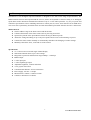
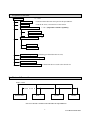
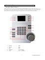
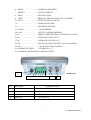
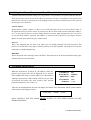
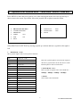
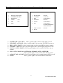
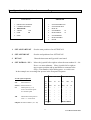
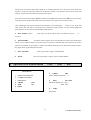
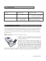
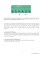
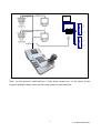
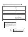
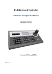
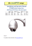
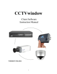
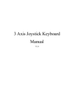
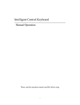
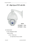
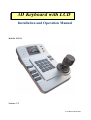
3D Keyboard with LCD
Installation and Operation Manual
MODEL PTZ725
Version 1.0
Last Revised 24/01/2011
CONTENTS
Page
1.
Summary
3
2.
Keyboard Functions
4
3.
External Connections
4
4.
The Keyboard Panel
5
5.
Setting the Address, Protocol and Baud Rate of the Dome
7
6.
Keyboard Specification
7
7.
Keyboard Operation
8
8.
Control of the Dome / Pan / Tilt
8
9a. Operation of the keyboard menu – Main Menu – Protocol – Baud Rate
9
9b.. Operation of the keyboard menu – Camera Setting
10
9c.
Operation of the keyboard menu – Program
11
9d.
Operation of the keyboard menu – Video – OSD – Exit
12
10. Troubleshooting
13
11. Installation and Connection
13
12. Keyboard Operation
16
13. Technical Specifications
20
2
Last Revised 24/01/2011
1.
Summary
The PTZ725 3 axis intelligent keyboard controller is designed for use with a wide range of Speed Domes. The
RS485 interface between the keyboard and the receiver, allows one keyboard to control as many as 32 intelligent
speed domes with a maximum communication distance of up to 1.2 km. The keyboard is very easy to operate and
control the Speed Dome Camera including functions to control pan, tilt, zoom, focus and also has an OSD menu
of its own. This is particularly beneficial when used with the standard speed dome that does not have a PTZ menu.
Main Functions
Sets the address range of the dome camera and the decoder.
Controls all functions of the dome camera such as powering on and off.
Operates the pan/tilt of the Speed Dome Camera moving at different speeds.
Allows the setting and calling of up to 128 preset points and six tours each containing 16 presets.
Controls the dome camera manually or automatically and allows the changing of camera settings.
Manually controls the focus, zoom and iris of the camera.
Specifications
2.5” Colour LCD screen with single channel display
OSD menu function allows up to 6 tour settings
Integrated 15 protocols and baud rate range 2400bps ~ 19200 bps
RS485 output
1 video input port
1 video loopthrough output
Adjustable brightness, contrast and colour
3 axis joystick movement
Communication distance: at best 1200 metres
Power Supply 12V DC / 1.0Amps
Measurements: 210mm x 130mm x 55mm
Controls a maximum of 32 domes
3
Last Revised 24/01/2011
2.
Keyboard Functions
Select Camera
0 ~ 1024
Joystick Control
Controls Pan/Tilt direction and speed of the Speed Dome.
Lens Control
Controls the focus, zoom and iris of the camera.
Operation of Preset Position
1~128 (Dependent on dome capability)
Set Preset Position
Call Preset Position
Operation of Tour/Patrol
1~6
Set Tour/Patrol
Run Tour/Patrol
Auto Scan Operation
(including speed and direction of scan)
Record Pattern Self-Learning Scan
Dome Menu Functions
Direct Control of the Decoder
3.
Control front devices such as the decoder etc.
External Connections
RS485 + A LINE
RS485 – B LINE
KEYBOARD
DVR
DOME
DOME
DO NOT CROSS CONNECT KEYBOARD TO EQUIPMENT
4
Last Revised 24/01/2011
4.
The keyboard Panel
Description of Buttons (Figure 1)
The keyboard has a speed joystick, press buttons and an illuminated display on the front panel. The display is used
for displaying camera video, OSD menu and for displaying camera data information. The joystick controls the
upward, downward, and sideways movement of the speed dome. The description of buttons is as follows:
1.
2
3.
4.
5.
ZOOM ……………… LED
FOCUS ……………… LED
IRIS ………………….. LED
DISPLAY ……..………...LCD SCREEN
CALL ………………….. CALL CAMERA
5
Last Revised 24/01/2011
6.
MENU
…………………INTERNAL OSD MENU
7.
PRESET
8.
SHOT
9.
LENS
………………SETTING PRESET
…………………SETTING TOUR
…………………..PRESS TO ADJUST ZOOM, FOCUS OR IRIS
10. AUTO …………………..SETTING FOR AUTOSCAN
11. + ………………………...INCREASE SETTING
12. - …………………………...DECREASE SETTING
13. CLEAR ……………………CLEAR PRESET
14. CAM ………………………SELECT CAMERA ADDRESS
15. M ………………………..DISPLAYS BRIGHTNESS, CONTRAST, COLOUR
16. M+ ………………………...INCREASE OPTION IN 15
17. M- …………………………DECREASE OPTION IN 15
18. ON ………………………...OPEN FUNCTION CONTROL (see Function Table)
19. OFF ………………………..CLOSE FUNCTION CONTROL
20. NUMERIC KEYPAD …….. NUMERICS 0 ~ 9
21. JOYSTICK CONTROLLER 3-AXIS JOYSTICK
REAR VIEW
1
2
No:
GND 12v -
+ - +
Description
3
4
Component Details
1
Power connection
12vDC 1A PSU
2
Communication Interface
Ground
3
Video In
PTZ video in
4
Video Out
PTZ video out
12vDC
6
RS485
-
+ -
+
Last Revised 24/01/2011
5.
Setting the Address, Protocol and Baud Rate of the Dome
A PTZ dome has three functions usually set by dip switches: a unique address, the protocol and the baud rate.
The keyboard must call the correct dome address and will only be able to communicate if the protocol and
baud rate are correctly set. The protocol is the language used by the dome and the baud rate is the speed of
the messages sent to the dome.
Camera Address
Each dome has a unique “address” so that if you are using more than one on a site, the keyboard “talks” to
the right dome when you want it to PTZ. If you only have the one dome on the site then the default “address”
of “1” is okay and you have no reason to change the dome from this. With multiple dome sites you need to
set up each dome address separately. The address is called from the keyboard by pressing the numeric
address set in the dome followed by the “CAM” button.
Protocol
This is the language that the dome uses when you are sending messages from the keyboard. The
protocol set in the dome must agree with the protocol set in the keyboard. The protocol used by the
keyboard is set in the keypad menu.
Baud Rate
This is the speed of the messages sent to the dome. The baud rate set in the keyboard menu must agree
with the baud rate set in the dome.
6.
Keyboard Specification
When the keyboard is powered on, the address, baud rate,
protocol and version code will be displayed for 10 seconds.
The CAMERA ID refers to camera address 001, Baud Rate is
2400 bps, the protocol is P003 which is PELCO-D (see table
of protocols and codes), the video format is PAL and the
keyboard software level is version 1.4.
CAMERA ID:
BAUD RATE:
PROTOCOL:
TV FORMAT:
VERSION:
001
2400BPS
P003
PAL
V1.4
After the 10 second duration, the unit will display the content of the data buffer and the camera address
at the bottom of the display window.
DATA: 0000
DOME
ID: 001
ONLY CONNECT THE PTZ DOME AFTER SETTING UP THE DOME DETAILS IN THE
KEYBOARD MENU.
7
Last Revised 24/01/2011
7.
Keyboard Operation
Function
Select Camera
Set Preset
Call Preset
Clear Preset
Run Tour
Set AutoScan (L)
Set AutoScan (R)
Run AutoScan
Zoom Control
Focus Control
Iris Control
LCD Display
Brightness
LCD Display
Contrast
LCD Display
Colour
8.
Operation
<camera number 1 ~ 1024> CAM
<preset number 1 ~ 128> PRESET
<preset number 1 ~ 128> CALL
CLEAR <preset number 1 ~ 128> PRESET
<tour number> SHOT
Move to start position & AUTO ON
Move to end position & AUTO OFF
<Autoscan number> AUTO
Press LENS until ZOOM lights, then press
the + or – to adjust zoom
Press LENS until FOCUS lights, then press
the + or – to adjust focus
Press LENS until IRIS lights, then press the +
or – to adjust iris
Press M then M+ or M- to make lighter or
darker
Press M, then M again to select Contrast then
M+ or M- to set contrast
Press M, then M again and M again to select
Colour then M+ or M- to set colour
Example
2 CAM
5 PRESET
3 CALL
CLEAR 7 PRESET
1 SHOT
AUTO ON
AUTO OFF
1 AUTO
LENS until ZOOM lights then
+ or – to adjust
LENS until FOCUS lights then
+ or – to adjust
LENS until IRIS lights then +
or – to adjust
M, then M+ or M- to set
brightness
M, M, then M+ or M- to set
contrast
M, M, M then M+ or M- to set
colour
Control of the Dome / Pan / Tilt
Control of the Dome
Move the joystick until camera reaches desired position. To gain the fastest movement, move the
joystick upwards from centre position. The speed of movement can be controlled by the speed of
movement on the joystick. To zoom in or out twist the joystick clockwise or anti clockwise.
8
Last Revised 24/01/2011
9a.
Operation of the keyboard menu
- Main Menu - Protocol – Baud Rate
Press MENU to enter and press again to exit. After entering the menu, move the joystick up or
down to move the cursor up or down. Move the joystick left or right to enter the menu .
MAIN MENU
1.
2.
3.
4.
5.
6.
PROTOCOL SETTING
1.
2.
3.
PROTOCOL SETTING
CAMERA SETTING
PROGRAM
VIDEO
CH1
OSD
ON
EXIT
PROTOCOL
BAUD RATE
BACK
P003
2400
Select PROTOCOL SETTING by moving joystick up or down and move joystick to the right or
left.
1. PROTOCOL <code>
Move joystick right or left to select protocol from list:
CODE
PROTOCOL NAME
P000
A01
P001
B01
P002
SANTACHI
P003
PELCO-D
P004
PELCO-P
P005
PANASONIC
P006
LONGCOMITY
P007
HD600
P008
LILIN
P009
VICON
P010
MOLYNX
P011
KALATE
P012
VCL
P013
RESERVED
P014
ALEC
P015
ULTRAK
Move the joystick right to select the item required
then move joystick down to the next item or to the
BACK option to return to main menu.
2. BAUD RATE <rate>
Move joystick to right or left to select baud rate :2400bps – 4800bps – 9600bps – 19200bps
3. BACK
This returns to the main menu.
9
Last Revised 24/01/2011
9b.
Operation of the keyboard menu
.
Camera Setting
MAIN MENU
1.
2.
3.
4.
5.
6.
CAMERA SETTING
PROTOCOL SETTING
CAMERA SETTING
PROGRAM
VIDEO
CH1
OSD
ON
EXIT
1.
2.
3.
4.
5.
6.
BACKLIGHT
ICR SHOT
IRIS
D-ZOOM
FOCUS
WB
7. OSD OF CAM
8. BACK
ON/OFF
AUTO/ON
AUTO/MANU
OFF/ON
AUTO/MANU
AUTO/MANU
OUTDOOR/INDOOR
ATW/ONEPUSH
ON/OFF
1.
2.
3.
4.
5.
BACKLIGHT <ON / OFF > Move joystick right or left to switch light on or off.
ICR SHOT <AUTO/ON > Move joystick right or left to switch ICR SHOT auto or on.
IRIS <AUTO / MANU > Move joystick right or left to switch IRIS to auto or manual.
D-ZOOM < OFF/ ON > Move joystick right or left to switch digital ZOOM on or off..
FOCUS < AUTO / MANU > Move joystick right or left to switch FOCUS to auto or
manual.
6. WB < AUTO / MANUAL / OUTDOOR / INDOOR / ATW / ONEPUSH >
Move joystick right or left to switch white balance option.
7. OSD OF CAM < ON/OFF > Move joystick right or left to switch camera OSD on or off.
8. BACK
Move joystick right or left to RETURN to main menu.
10
Last Revised 24/01/2011
9c.
Operation of the keyboard menu
-
Program
MAIN MENU
1.
2.
3.
4.
5.
6.
PROGRAM
PROTOCOL SETTING
CAMERA SETTING
PROGRAM
VIDEO
CH1
OSD
ON
EXIT
1.
2.
3.
4.
5.
6.
7.
8.
SET AP START POT
SET AP END POT
RUN AP
SET PATROL
01
RUN PATROL
01
SET PATTERN
RUN PATTERN
BACK
1. SET AP START POT
Sets the start position of an AUTOSCAN
2. SET AP END POT
Sets the end position of an AUTOSCAN
3. RUN AP
Runs the Autoscan until joystick is activated
4. SET PATROL < NN >
Move the joystick left or right to select the tour number 01 ~ 06.
Press + to enter submenu. Move joystick left or right to
move cursor position and up and down to set menu value.
SEQ = Tour number. After editing press - to exit & save.
In the example we are setting four presets in the first patrol sequence.
NO POS SP TM
POS SP TM
To edit a patrol sequence
NO
Patrol Item No.
POS No. of Preset Position
SP
Dome speed (0, 1~8)
0 and 1 are fastest speed –
8 is slowest speed
TM
Dwell time at this position
Time 0 ~ 99 seconds
01
001
01
03 003
05 --07 --09 --11
--13 --15 --SEQ:01
01
01
01
-------
01
-------
01
002
01
004
01 01
------------------------MINUS:EXIT
SEQ:nn The Patrol number. (01 ~ 06)
11
Last Revised 24/01/2011
Special Note: The patrol item number (NO) is an ascending number list of the preset items within this
sequence. It may not necessarily reflect the actual preset number. You could for instance have preset item
(NO) 01 with preset position 004 as the first preset required.
Enter the preset position number (POS), the dome speed (SP) and the dwell time (TM) for each preset by
using the Joystick up/down movement. Move the Joystick to the right to move to the next field.
After including all the presets required in this patrol/tour, press the Keypad
- button to exit. If you add
extra presets later and wish to incorporate into a patrol/tour already created, you must add the additional
preset positions in the necessary SET PATROL table sequence.
5.
RUN PATROL < NN >
Move joystick to left or right to select tour number and press + to
start tour.
6.
SET PATTERN
Set Pattern allows a pattern to be recorded which consists of any standard pan
and tilt or lens command within a 40 second interval. A pattern is automatically closed when the 40 second
interval is exceeded or by pressing the - button. Note that the following are not allowed in a pattern: presets,
flip, digital zoom, proportional pan and turbo.
9d.
7.
RUN PATTERN
8.
BACK
Move joystick left or right to run PATTERN.
Move the joystick left or right to return to MAIN MENU.
Operation of the keyboard menu
Video
-
OSD
-
Exit
MAIN MENU
1.
2.
3.
4.
5.
6.
4.
VIDEO
CH1
Picture channel selection 1 ~ 4
PROTOCOL SETTING
CAMERA SETTING
PROGRAM
VIDEO
CH1
OSD
ON
EXIT
5.
OSD
ON / OFF
Character display ON – open
OFF - close
6.
EXIT
Quit menu
12
Last Revised 24/01/2011
10.
Troubleshooting
Problem
Possible Cause
Possible Solution
No video
No power supply
1. Check power connection
2. Check 12vDC power supply
3. Check video connection
Protocol and baud rate must be
matched in keyboard and dome.
Correct address must be called.
No telemetry control
11.
1. Incorrect protocol
2. Incorrect baud rate
3. Incorrect address
Installation and Connection
Please read the keyboard and speed dome manuals carefully before connecting wires. Any incorrect connections
can cause permanent damage to the equipment. When connecting wires, always switch off the power supply first.
The PTZ725 keyboard must not be exposed to damp or wet conditions that may short circuit the unit or cause
electric shock.. Always check that the keyboard is correctly connected to a regulated 12v power supply and that
the polarity is correct.
RS485 connection - Connecting the Keypad to the Dome.
The dome is controlled by an RS485 data signal that is produced by
the PTZ715 keypad or a compatible DVR. This data signal tells the
dome to pan, tilt, zoom etc.
RS485 has two cores, A and B or sometimes known as RS485 + (A)
and RS485 – (B) if you get these two the wrong away around then
you will not be able to control the dome. Sometimes installers get
the connections right on one dome but not on the other and find
only one dome works. They then swap the wires around at the
keyboard only to find out one dome has now burst in to life and the
other one now failed!! But they don’t put 2 + 2 together and realise
their mistake that they have wired one dome different to the other.
Take great care getting these the right way around and make sure you wire each dome IDENTICALLY so
that if you have to swap the A & B lines over at the keyboard you know all domes are wired the same!!
13
Last Revised 24/01/2011
GND
12V
+
+
Connect the RS485 data cable to the connections on the rear of the keyboard (see diagram above). Note that
the RS485 + is the T+ connection and the RS485 – is the T- connection. Note that there are two sets of
RS485 connections available and either or both sets can be used.
It is advisable to use CAT5 cable to connect the RS485 data cable from the dome to the keypad. You could use any
pair out of the CAT5 cable but they must be two cores from the same pair. If you use cores from two different
pairs in the CAT5 cable you will not get the benefit of the shielding effect of the cable twists and the dome will
function erratically. You must always use a core from a PAIR, not two cores from two different pairs!! When
installing cables they should be far away from high voltage lines or other possible sources of electrical
interference.
Powering the PTZ725 Keypad
The PTZ725 requires a 12v DC regulated power supply and draws in the region of 1Amp. It is suggested that to
ensure longest life from the power supply that a minimum specification of a 12v DC 1A regulated power supply is
fitted. The power supply fitting required is a 2.1mm mini power jack plug that fits into the 2.1mm mini power jack
socket on the rear of the keypad.
Connecting the Keypad to Multiple Domes
The diagram below shows how to connect multiple domes to the PTZ725 keyboard controller.
Connections at the camera end are shown below.
14
Last Revised 24/01/2011
RS485
T+
T-
1
2
3
4
5
6
7
8
ALM
ALM
DC IN
GND
R+
RVIDEOVIDEO+
DOME SP EED 1
ALM
1
ALM
2
DC IN
3
GND
4
R+
5
R6
VIDEO7
VIDEO+
8
DOME S P E ED N
MENU
Note: As the protocol and baud rate of the dome camera are set by menu in this
keypad, multiple domes must use the same protocol and baud rate.
15
Last Revised 24/01/2011
12.
Keyboard Operation
Camera Address.
In order to control the dome you will need to uniquely address it. The dome will usually have dip switches to
set the address. When the address is set you will need to use this address to access the specific dome.
Press the dome address followed by the CAM key.
Example:
Press ‘1’ followed by CAM button. This will allow you to control camera 1.
Press ‘3’ followed by CAM button. This will allow you to control camera 3.
Introduction to Dome’s functionality
The dome stores preset positions, preset tours and other functionality associated with the dome equipment.
The keyboard merely instructs the dome to carry out those functions. Think of the keyboard as a switch that
activates a particular function in the dome that you require. Not all domes have the same functionality so if
your dome does not have presets built into it you obviously cannot use presets, regardless of the keyboard
you use. The 2.5” (measured diagonally) colour LCD screen will display the video channel and menus.
PRESETS and other functions.
What is a preset? A preset is a particular area or object that the dome camera was looking at and has been
stored into its memory so when the preset is “called-up” from the keypad, the dome will select the area again
without the operator using the joystick to do this. Even the zoom at the time can be stored with the preset.
This means that you could for example store a PRESET of a car-park entrance. When the operator calls up
this preset from the keypad, the camera automatically zooms in on this area. This keypad can select up to 128
different presets. Of course this is dependent on the total number that can be programmed into the dome.
Once programmed they will stay in the dome’s non-volatile memory so they will be retained even after a
power cut. By storing more than one preset you can add even more functionality to the dome. By having two
Autoscan points, you can then get the dome to “SCAN” between the two locations. You can even vary the
speed of this scan. Having 3 or more presets you can get the dome to go on a TOUR (PATROL) of the
presets. When you run the patrol, the dome goes to one preset, then waits a short period then on to the next
preset and so on. The dome continues to cycle around this patrol until you cancel it.
Please note that the ability to use presets, auto scans, tours, record patterns, the length of time the
camera stays at one location and the speed of travel between each preset, are dependent on the
functionality available in the dome. Always refer to the relevant dome instruction manual.
PRESETS -How to set up a preset
Aim the dome where you want it to look, zoom in or out to get the correct scene and let the camera auto
focus. Now press the following keys on the keypad : xx PRESET (where xx is the preset number you wish
to store). For example
01 PRESET would set preset 1 and the camera would always go to this location
when preset 01 is “CALLED”.
16
Last Revised 24/01/2011
To test if the preset is stored correctly in the dome, use the joystick to move the camera to point in a new
location. Now press xx CALL (where xx is the preset you wish the camera to go to). In this example if
you press 01 CALL the dome should go straight to the PRESET 01 location.
TIP -You may wish to write down a list of presets that you have stored next to the keypad for the operator.
CALLING a preset
This may be as follows;
PRESET 01 = MAIN GATE (a long zoom shot)
PRESET 02 = ENTRANCE DOOR
PRESET 03 = FIRE ESCAPE
PRESET 04 = EMERGENCY EXIT
PRESET 05 = CAR PARK (zoomed-out wide angle)
PRESET 06 = CAR PARK (zoomed-in narrow angle)
When the operator wishes to quickly zoom in on the MAIN GATE all he has to do is press
01 CALL
To go to the EMERGENCY EXIT he would press 04 CALL and so on.
To call up any previously stored preset camera location, simply press xx CALL where xx is the preset
number.
Deleting a preset
You may wish to delete a preset.
To do this press CLEAR xx
PRESET (xx = preset number).
For example to delete preset 1, press CLEAR 01 PRESET. Obviously if you wish to overwrite a preset with
a new location, simply aim the camera at the new location and store the same preset again.
Patrols (Tours) – How to set them up and use them
A patrol (tour) is simply a collection of at least three preset camera locations that are run in sequence with
the dome stopping at each location for a brief period of time and then moving on to the next preset.
For example, you could use a patrol so that an outside dome camera points at a gate, then at a side doorway,
then zooms out to get an overall shot of a car park and finally zooming in on a delivery bay, before repeating
the whole cycle again. Patrols can be useful for both outside and internal PTZ’s. For a shop they could be
used to cover key areas like clothes rails, tills and changing rooms in a sequence.
To set up a patrol you need to set up the individual stop points where the camera will pause. These are called
presets.
17
Last Revised 24/01/2011
An example four preset mini-tour
Setting the presets using the keypad
STEP 1- Using the keypad joystick, move to the first position and then press 01 PRESET
STEP 2- Now move to the next location and press 02 PRESET
STEP 3- Now move to the third location and press 03 PRESET
STEP 4- Finally move to where you wish to end the tour and press 04 PRESET
Setting up a Tour/Patrol
Refer to your instructions on the dome. This will detail how the tour is set up and initiated via the dome
menu. In order to access the dome menu press 95 CALL. You can select items in the menu by using the
joystick left and right movement or moving up and down using the joystick movement. Alternatively you can
use the keyboard menu by pressing the MENU button.
Running a Tour/Patrol
Refer to your dome instructions. This will detail how to initiate the Tour/Patrol via the dome menu. In order to
access the dome menu press 95 CALL (PTZ400/600). You can select items in the menu by using the
joystick left and right movement or moving up and down using the joystick movement. Alternatively you can
use the keyboard menu by pressing the MENU button. Alternatively you may be able to initiate the
Tour/Patrol directly from the keypad by pressing the sequence number of the Tour/Patrol already stored in
the dome followed by the SHOT button. Example 01 SHOT where 01 is the stored tour/patrol selected.
SPECIAL NOTE: You should read the PTZ camera instructions because some PTZ cameras use different control
codes to initiate a tour. Some PTZs require a 51 PRESET (PTZ500) and some use a 53 CALL (PTZ250).
Setting up an Auto Pan/Scan
Refer to your instructions on the dome. This will detail how the Auto Pan/Scan is set up and initiated. In
order to access the dome menu press 95 CALL (PTZ400/600). You can select items in the menu by using the
joystick left and right movement or moving up and down using the joystick movement. Alternatively you
may be able to set up an Auto Pan/Scan directly from the keypad. First move dome to start position and then
press the AUTO + ON buttons. Next move dome to the end position of the Auto Pan/Scan. Now press the
AUTO + OFF buttons.
SPECIAL NOTE: You should read the PTZ camera instructions because some PTZ cameras use different control
codes to setup a scan. Some PTZs require a 52 PRESET (PTZ500) to set the start point and 53 PRESET
(PTZ500) to set the end point.
Running an Auto Pan/Scan
Refer to your dome instructions. This will detail how to initiate the Auto Pan/Scan via the dome menu. In order to
access the dome menu 95 CALL (PTZ400/600). You can select items in the menu by using the joystick left
and right movement or moving up and down using the joystick movement. Alternatively you may be able to
initiate the Auto Pan/Scan directly from the keypad by pressing 01 AUTO.
18
Last Revised 24/01/2011
SPECIAL NOTE: You should read the PTZ camera instructions because some PTZ cameras use different control
codes to run an autoscan. Some PTZs require a 51 CALL (PTZ500) to start an Autoscan at low speed, 52 CALL
to start an Autoscan at normal speed and a 53 CALL at high speed.
Setting up a Record Pattern/Self Learning Scan (PTZ400/600 series)
Refer to your instructions on the dome. This will detail how the Record Pattern is set up and initiated via the dome
menu. In order to access the dome menu press 95 CALL. You can select items in the menu by using the
joystick left and right movement or moving up and down using the joystick movement. Alternatively you can
use the keyboard program menu. To do this press MENU button and select PROGRAM, then moving down
using joystick to set pattern by moving joystick right. Press – to exit.
Running a Recorded Pattern/Self Learning Scan (PTZ400/600 series)
Refer to your dome instructions. This will detail how to run the Record Pattern via the dome menu. In order to
access the dome menu press 95 CALL. You can select items in the menu by using the joystick left and right
movement or moving up and down using the joystick movement. Alternatively you can use the keyboard
program menu. To do this press MENU button and select PROGRAM, then moving down using joystick to
run pattern by moving joystick right. Press – to exit. To stop the running of a Record Pattern just move the
joystick.
Remember that the keyboard does not store presets or commands. This is done by the dome’s non-volatile
memory, which retains settings even through loss of power. Note however that this keyboard has been
designed to control a wide variety of PTZ domes and that some functions may not be operable according to
the functions provided by the dome.
SPECIAL NOTES
When using PTZ725 to control a PTZ605
Both the PTZ725 and the PTZ605 have an internal menu that can be edited. The menus can run
independently of each other but cannot override each other. You can therefore run a totally separate tour via
the keyboard to the one setup in the PTZ605 menu and this will not affect it.
When using a PTZ725 to control a PTZ505
The PTZ505 does not have an internal PTZ menu only a camera menu. Therefore using the PTZ725 menu
provides a control menu not previously available. Whilst the PTZ505 does not cater for patterns, the use of the
menu allows the setting of up to six tours that were previously not available.
19
Last Revised 24/01/2011
13.
Technical Specifications
Communication between dome camera & PTZ725
Half duplex multipoint communication
Communication connector
RS485
Communication Baud Rate
2400bps, 4800bps, 9600bps and 19200bps
Maximum communication distance
1200 metres maximum
Power Supply
12v DC 1Amp
Screen Display
2.5” colour LCD
Joystick Control
3 – Axis variable speed joystick
OSD Menu
Size
Menu allowing setting of protocol, baud
rate, camera adjustment, and programming
tours, autoscans and patterns.
210mm x 155mm x 92mm (inc joystick)
Number of domes controlled by keyboard
32
All specifications are approximate. Kovert.com reserves the right to
change any product specifications or features without notice. Whilst
every effort is made to ensure that these instructions are complete and
accurate, kovert.com cannot be held responsible in any way for any
losses, no matter how they arise, from errors or omissions in these
instructions, or the performance or non-performance of the equipment
that these instructions refer to.
This symbol on the products and/or accompanying documents means
that used electronic equipment must not be mixed with general
household waste. For treatment, recovery and recycling please return
this unit to your trade supplier or local designated collection point as
defined by your local council.
WEE/CG0783S
20
Last Revised 24/01/2011