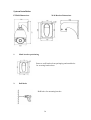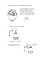
1
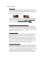
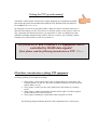
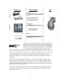
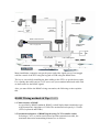
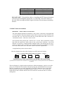
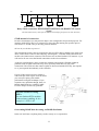
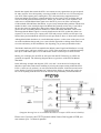
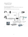
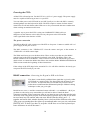
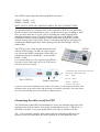
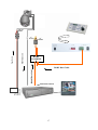
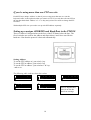
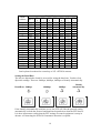
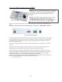
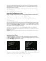
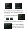
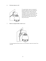
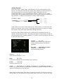
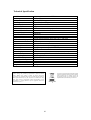
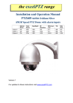
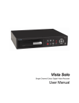
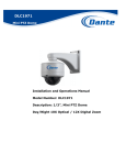
PTZ Dome + Intelligent IRs
Installation and Operation Manual
PTZ630 HIGH Speed Pan Tilt Zoom
24V AC model with Intelligent IRs
Models Covered
PTZ630K 27 x Zoom
PTZ630P 36 x Zoom
Version 2.0
Last Revised: 14/12/2012
1
CONTENTS TABLE
Description
Page No.
Contents
2
Please read the following
3
Key Functions
4
Technical Descriptions
5
Compatible Keyboards
6
Getting the PTZ up and running
7
RS485 Wiring methods and Tips
9
RS485 Connection methods
10
Star method of connection
11
Overcoming RS485 data loss using an RS485 distributor
11
Setting up the PTZ camera
13
Powering the PTZs
14
RS485 connection – Connecting the keypad or DVR to the Dome 14
Connecting the video out of thr PTZ
15
Using more than one PTZ on a site
18
Setting up a unique Address and Baud Rate in the PTZ630
18
Setting the Baud Rate
19
Using the PTZ630 keypad with the PTZ630
20
Presets and other functions
21
Presets – How to setup a preset
21
Calling a preset
21
Patrols/Tours – How to set them up and use them
21
Deleting a preset
22
Setting the Patrol/Tour
22
Calling the Patrol/Tour
24
Auto Scan – how to set it up Autoscan between 2 points
24
Calling the Auto Scan
25
Record Pattern
25
Running the Record Pattern
27
Preset Function Table
27
Using the Dome’s Advanced Functions
28
The Menu System
28
System Installation
36
Alarm Feature
39
Entering the Camera Module Menu
40
Technical Specification
41
2
Please read this operation manual carefully
before installing and using this unit !!!!
Please read the following;
1. Please read the operation manual carefully before installing and operating the product.
2. The PTZ630 requires a 24v AC 2A power supply. The rated input voltage of the camera in
the PTZ is 12V!!!! This gets its power from the PTZ630 and does not require a separate
PSU. Do not connect 24V AC to the internal camera module under any circumstances!!
3. During the course of transportation, storage and installation, the product should be
handled with care avoiding vibration and any weight pressure, which may cause damage
to the sophisticated optical and electronic equipment inside the machine.
4. Do not attempt to disassemble the camera. In order to prevent electric shock, do not
remove screws or covers. There are no user-serviceable parts inside the camera.
5. Always use and stick to current electrical safety standards to install and use the PTZ630.
Use a correctly rated power supply. The RS-485 and video signal cables should be kept
way from other high voltage equipment such as mains cables and especially fluorescent
lights. Using an anti surge protection device is recommended to prevent damage to the
PTZ630 from lightning and mains surges. Damage to units by lightning or mains voltage
surges is not covered under the product warranty.
6. Do not operate in areas exceeding the stipulated limitations concerning temperature,
humidity and power supply.
7. Do not aim the camera directly towards the sun or an extreme light source whether it is
switched on or not. Do not let the camera focus on bright and stationary objects for a long
time. Doing either of these may damage the camera.
8. Do not use strong detergents to clean the main body of the camera as these may damage
the PTZ paintwork. Wipe dirt away with dry cloth. If needed a mild detergent can be used.
9. Operate the PTZ camera with care avoiding shock or vibration. If operated incorrectly, the
PTZ could be damaged.
10. Ensure the PTZ is not dropped. The PTZ630 weighs approximately 4Kgs so never mount
the unit on a structure that cannot support its weight.
11. When this unit is in use, avoid direct eye contact with the infrared lights.
12. The unit’s outer IR transparent cover can heat up when in use and care should be taken to
ensure that this PTZ is fitted where it cannot be easily touched. It must also not be fitted in
close proximity of any flammable materials.
3
The PTZ630
KEY
FUNCTIONS
Description of Product Features
This intelligent IR PTZ dome is a hi-tech CCTV product incorporating a high-clarity
colour camera with a choice of two modules. The 27x zoom K module or the 36x
zoom wide dynamic module.
1. Intelligent Functionality
a. IRs are selected automatically according to the zoom setting, providing wide
or narrow angle IR illumination.
b. Incorporates automatic protocol and baud rate diagnosis which means these
are set automatically.
2. High Speed Horizontal and Vertical rotation
a. The PTZ can rotate at a maximum speed of 200ºper second.
b. The PTZ630 incorporates Vector driver technology ensuring PTZ takes the
shortest route.
c. Due to the precision stepping motor technology utilised in this PTZ, the
lowest rotation speed that can be accomplished is 0.6ºper second. This
provides very accurate control in long distance zoom operations.
3. Presets, Tours, Patterns and Auto Scan
a. The PTZ630 can set up to 220 presets, each preset containing the lens zoom
and angle positions.
b. You can set up to 8 tours (Patrol Tracks) each with up to 32 presets.
c. Can record in Mode Scan up to 4 patterns, with each pattern containing up
to 100 movements.
d. Using two presets points you can setup an Auto Scan that can run at low,
medium or high speed, internally between the preset points or externally.
e. Continuous 360ºscan option available.
4. PTZ Control
a. The PTZ630 uses RS485 communication protocol. The unit pans 0 ~
360ºwith continuous rotation, Tilts 0 ~ 90ºwith auto flip and has no blind spots.
The unit pan speed is from 0.6º~ 200ºper second and tilt speed 0.8º~ 75ºper
second. The speed can be adjusted automatically according to the lens zoom
range.
5. NiteDevil Feature
a. The NiteDevil camera module incorporates a slower shutter speed allowing
the camera to see more at low light levels. This camera having Infra Red
capability allows it to see in total darkness.
6. Alarm Function
a. The PTZ630 has 3 alarm inputs. Alarm channels can be triggered to move the
camera to a defined preset, start a tour or start a pattern.
4
Technical Descriptions
Infrared System
The infrared system runs normally under automatic control. The PTZ630 has an
automatic intelligent IR light facility that is coupled to the focus operation so that
wide angle shots are given a wide diffused IR beam whilst longer distance shots re
given a more powerful narrower IR beam.
The Infrared lamps illuminate in a low light condition and switch off when light
levels improve. A menu default option is set to AUTO for normal operation. The
user may set the option to ON to force the Infrareds to illuminate but if it is
required to return to normal mode the option must be set to AUTO.
Automatic RS485 Protocol and Baud Rate recognition
The PTZ630 is able to recognise the protocol and baud rate when connected to
control equipment. However in the System Information menu you can enable the
Soft Address (ID) which then allows you to software change the ID from the Hard
Address that reflects the address of the physical ID dipswitch setting located on the
dome face under the protective cover.
Controlling the PTZ630
In order to access the PTZ630 menu via keyboard or Alien DVR call preset 95. To
move up and down the menu use the up or down direction key or joystick
controller. Move right to enter the selected option. To change the option press the
IRIS+ button which changes the white circle to the left of the option to a clear
circle, and then use the up and down direction keys or joystick controller up or
down movement, to alter the value. Then press the IRIS+ button again to save the
change and the clear circle will change to a white circle. When all changes made,
move down to Exit and press the Iris - button and exit out of menu.
Using the Alien Max (Alien716)
To set a preset point using the Alien716 select the PTZ option by clicking on the
Menu, then Video, PTZ then More Settings. Ensure Save Preset button is selected
and move camera to first preset point and click on Preset Number. Setting Preset
xxx (where xxx = preset selected) is then displayed in Display window. Then using
arrow buttons move camera to next preset point and set next preset point.
To initiate a tour using the Alien716 you can select the PTZ option by clicking on
the Menu, then Video, PTZ then More Settings. Go to Patrol x and using down
5
arrow select the required Patrol number. Now click on the Add Keypoint button
and select each Preset Number (Preset 1 ~ 127), Duration (1 ~ 255 seconds at this
keypoint) and Speed (0 ~ 7 with 0 being slowest speed). Repeat this for each
preset set. Now click on the Right Arrow Run button to start patrol/tour. Select
Back and Exit menu.
Compatible Keyboards PT710, PTZ730, PTZ790
Using the joystick move the PTZ to first preset position. Press Preset, Preset
Number then Enter. A "Setting Preset xxx" will then be displayed. Repeat this
for each preset set. To start the patrol/tour select Shot/Call, Tour Number (65
~68 patrol/tour 1 ~4 or 231 ~ 238 call patrol/tour 1 ~ 8) followed by Enter.
Compatible Keyboard PTZ715, PTZ725
Using the joystick move the PTZ to first preset position. Press Preset Number
then Preset button Enter. "A Setting Preset xxx" will then be displayed. Repeat
this for each preset set. To start the patrol/tour select Tour Number (65 ~68
patrol/tour 1 ~4 or 231 ~ 238 call patrol/tour 1 ~ 8) followed by Shot/Call.
6
Getting the PTZ up and running!
You MUST connect up the PTZ and your control equipment on a workbench or kitchen
table before the actual site installation and CHECK YOU KNOW HOW TO INSTALL
IT CORRECTLY!!!!!!!!!!!!!!!!!.
By doing this you can set-up any DIP switches, adjust the camera, and learn about how it
operates before taking it to site. This will save you hours of time on-site trying to work out
why a particular item doesn’t function as you expected it to. There is nothing worse than
installing something and then having to take it down to see how to get it working!! Do the
learning curve in the comfort of your own premises!!!!
Do you KNOW how to install PTZ equipment that is
controlled by RS485 data signals?
If not please read the following introduction to PTZ >>>….
Overview- introduction to fitting PTZ equipment
Generally speaking, PTZs require four things;
1- They require a power supply and a cable to supply this power to the PTZ. The
PTZ630 operates on 24V A.C like many external PTZ domes but some mini pan
and tilt domes are 12V.
2- They require a cable to get the video signal back to the monitor or recording
device.
3- They require a cable to transmit the “RS485 control signal” from the keypad or
DVR to tell the PTZ to pan and tilt etc.
4- They require something to control them, either a keypad or a DVR.
The following diagram indicates the basic cable requirements for a PTZ system.
7
Equipment
Cable Needed
PTZ
Control Equipment
1. Data signal
CAT5 cable
Keyboard or
DVR
You can also send the video signal
back along a second pair in a CAT5
cable using baluns. Note you cannot
send 24v AC power down CAT5.
Display Equipment
2. Video signal
RG59 or similar
You can combine both the video
and power into one cable if you
wish using composite cable.
Monitor
24V AC
Out
3. Power
Two core cable capable of carrying at least
3Amp @ 24V AC.
Power Supply
You can get “composite” cables that will carry both the power
and the video signals and this has the benefit of combining two
of the three cables into one. You may choose to power the PTZ
locally to it, so you may only need to get the video signal back
from the PTZ and the RS485 control signals to it. If this is the
case you may choose to use a pair of BALUNS. By using baluns you can send the video
signal and control signal down the same CAT5 cable just using different cores for each signal.
The control signal (RS485) is nearly always sent along a “twisted-pair” type cable. The twists
in the cable help prevent interference affecting the data signal by “shielding” it. Many
installation companies use a CAT5 type or similar cable to run out to the PTZs to carry the
data signal.
If you are considering using baluns please note - DVR’s tend to require very good video
signals to function correctly and “passive baluns” can loose some signal strength over the 50
metre mark so try to restrict the use of passive baluns to below 50 metre cable runs when
using them with DVRs. Above this distance perhaps consider an active balun. Active baluns
require power, passive baluns do not.
BALUN
You can mix and match how you wire up your PTZ installation and the following general
diagram gives you a guideline about how to do it. Remember this is a GUIDE and is not an
instruction what to fit!
8
CAT5 Carries Video & Power
24 V AC
240V ---
LOCAL
PSU
CAT5 Carries
Video &
Control Data
RG59+2 Video & Power
BALUN
CAT5 Carrying Data
JUNCTION BOX
CCT CAMERA
Video
& Power
RG59+2 Carries
BALUN
PTZ
CAT 5
TRADITIONAL
CAMERA
12V
DC
PSU
Free Lead Supplied
CO-AX RG59
DVR
KEYPAD
MONITOR
Many installation companies can get the power and video signal correct, but struggle
with the control of the PTZ using the keypad or DVR using the RS485 data.
The key to successfully installing the data cabling to the PTZ is to get the basics right.
Use a quality data cable such as CAT5 (never use just a standard untwisted cable such
as alarm cable for the RS485 signal).
Also, you must follow the RS485 wiring convention; the following section explains
this:
RS485 Wiring methods & Tips >>>>>
1. Characteristics of RS485
As specified by RS485 standards, RS485 is a half-duplex data transmission type
with characteristic impedance of 120 . The maximum load capacity is 32 units
(PTZs, keyboards and DVRs).
2. Transmission distances of RS485 Signals using CAT5 or similar cables
Selecting a CAT5 or similar sized twisted pair data transmission cable, the
maximum theoretical transmitting distances are as follows:
9
240V
AC
Baud Rate
2400 Bps (PELCO-D)
4800 bps
9600 bps
Maximum Transmitting Distance
1500m
1000m
600m
PLEASE NOTE - Using inferior cables, or installing the PTZ in an environment
with strong electromagnetic interference, or connecting a lot of PTZ domes to
the same cable carrying the RS485 signal will reduce the maximum transmitting
distance.
3. RS485 Connection methods
METHOD 1 – DAISY CHAIN CONNECTION.
The general RS485 standard recommends a “daisy chain” connection of equipment that
is to be controlled. This means that the control cable is looped out of the one PTZ to the
next PTZ and so on. The last PTZ in the line is then fitted with what is known as a
“termination resistor”. This has a value of 120 .
The keyboard itself generally has a built-in 120 resistor. These termination resistors
help make the signal more stable and give the system better reliability so the PTZs
function as expected. A common mistake installers make is not making sure the 120
resistor is fitted on the LAST PTZ. Also installers often set the termination in another
PTZ in the chain; these errors will make control of the PTZ unpredictable.
A simplified Daisy chain is shown below:
This first diagram shows the cables looping in one PTZ and out of another;
. . . . .
120
1#
2#
3#
4#
120
32#
Standard Daisy-Chain connection for the RS485 PTZ control signal
(just the last PTZ should have the 120 resistor set to on, the first device is the keyboard and has the 120 built in
as default)
This next diagram is a slight variation on the Daisy Chain arrangement. Again it’s one cable
going out to all the PTZs but instead of the cable going into each PTZ then back out to the
next one, a junction box is used to “Spur-Off” to each PTZ. Whilst this can be done THE
SPUR LENGTH (D) must be NO MORE THAN 10 metres!!!!!!!!!!!! The overall cable
length between the Controller and the last PTZ is limited to around 300 metres in such an
arrangement.
10
A+
. . . . .
BD
A+
B. . . . .
120
Main controller
1#
2#
3#
120
31#
Daisy-Chain connection WITH SHORT SPURS for the RS485 PTZ control
signal
(one main radial with very short spurs to each PTZ off it, keeping the spurs to less than 10 meters)
STAR method of connection.
In some circumstances you may need to adopt a star configuration for practical purposes. For
instance, all the PTZs may be so scattered on a large site that running out separate spurs to
each PTZ in a “STAR” array is the only practical solution.
So how do you do this in practice?
The termination resistors must be connected to the two PTZs that are farthest away from each
other, such as PTZs 3 and 5 in the following “Star diagram”. Note that all the other PTZs do
not have the 120 resistor connected. The resistors are not fitted in these PTZ cameras so you
will need to fit one across the RS485 connections on the relevant domes.
As the star configuration is not in conformity with the requirements of RS485 standards,
problems such as signal reflections may arise, especially when there are long cable
connections. The results are that control signals are decreased and the PTZ may not respond
to, or just responds intermittently to the controller.
If your STAR circuit is not too extensive
with each spur in the region of 20-50 metres
you can expect quite good reliable
performance using this technique. If you
experience any problems though, there is a
RS485 distribution box available CODE
PT750 to help overcome any problems.
The Star circuit for wiring
PTZ’s.
The two furthest PTZs need the
120 resistors enabling. In this
example it’s PTZs 3 &5.
Overcoming RS485 data loss using an RS485 distributor
In the real world not everything always works exactly as it’s expected to!
11
RS485 data signals that control the PTZs’ movements are tiny signals that can get corrupted
for many reasons. Poor cable quality, not using a PAIR of cores from a CAT5 but using one
core from TWO separate pairs, running the CAT5 cable near mains equipment such as
florescent lighting all will have a detrimental effect on the signal. These are things that you
can correct with good installation practices. Where you wish to run several separate CAT5
cables out to send the RS485 data signal out to the PTZs you are in effect correcting the
STAR method of RS485 data distribution. As previously mentioned the problem with the Star
method is that it is not actually designed for RS485 but generally works okay if you follow
the previous notes on getting the 120 resistor setting right. One way that takes the
guesswork out of installing the Star method is to utilise an RS485 distributor. This has the
advantage that the RS485 signal is correctly distributed to the PTZs so that they behave as
expected. You can create up to 4 spurs to the PTZs and put up to 4 PTZs on each spur. Just
like the Daisy chain method the end PTZ on each spur needs to have a 120 resistor enabled.
Although the RS485 distributor is a small additional expense, it takes some of the guess work
out of the installation design and gives a more flexible approach to cabling which itself can
save time and money on the installation. Not forgetting you get more predictable results!
The RS485 distributor (PTZ750) amplifies the RS485 control signal and distributes it evenly
to 4 separate spurs, each spur can have up to 4 PTZs. This means that you could theoretically
have up to 4 individual spurs of over 1000 metres each to control up to 16 PTZs in total.
Ideally you would put just one PTZ on each spur from the PTZ750 but up to 4 PTZs are
generally acceptable. The following diagram shows a typical use of the PTZ750 RS485
distributor.
In the following example and diagram, PTZs 1,4,5 and 7 are at the end of each spur and
therefore require the 120 resistor enabling by moving the jumper setting within the PTZs.
PTZs 2,3 and 6 are all “midway” in each spur and do not need the 120 resistor and can be
left as default. The PTZ750 itself has four 120 resistors built in as shown and you do not
have to do anything with the PTZ750 as the resistors are permanently connected within it.
(Diagram showing how to use an RS485 distributor to improve PTZ control reliability)
Please note if you have the PTZ750 located within 5mtrs of the keypad or DVR you
can connect up to 3 of them in parallel.
12
Setting up the PTZ Camera
1.
Connection of the System
There are many ways to wire up a PTZ system.
If you have read the introduction at the beginning of these instructions you should have got a
good idea what your options are.
CAT 5
24V AC
240V ---
PTZ
CAT5 Carries
Video &
Control Data
LOCAL
PSU
RG59+2 Video & Power
BALUN
CAT5 Carrying Data
JUNCTION BOX
CO-AX RG59
CCT CAMERA
Video
& Power
RG59+2 Carries
CAT5 Carries Video & Power
PTZ
BALUN
BALUN
Below is a general schematic diagram showing you some of these options.
TRADITIONAL
CAMERA
12V
DC
PSU
Free Lead Supplied
DVR
KEYPAD
MONITOR
13
240V
AC
Powering the PTZsAll the PTZs will need power. For this PTZ it is a 24V A.C power supply. The power supply
must be capable of delivering at least 1.1A per PTZ.
You can either power each PTZ with its own PSU locally to it or have the PSU’s remotely
situated perhaps near the keyboard or DVR. The PTZs require a current of about 410mA
when LEDs are off and 850mA when LEDs are on. So you must take this into consideration
when working out maximum cable runs.
A popular way to power the PTZs is using our COMPOSITE VIDEO cable (or
shotgun as its also known) as this cable can carry the power to the PTZ and the
video signal back to the monitor or DVR.
The power connection
The RED & BLACK cable coming out of the PTZ are for power. Connect a suitable 24V A.C
power supply to this pair of cores.
The BNC connector is the “VIDEO-OUT” from the camera and goes to the monitor or
“VIDEO-IN” of a DVR camera input.
The White and Green cores are the data cables. These are the cores that carry the RS485
control signal to the PTZ from either the keyboard or the DVR. The White cable is the
RS485+ and the Green is the RS485 - cable. The next section of the instructions gives more
detail on how to connect the RS485 data. Please also read the RS485 WIRING METHODS &
TIPS section towards the beginning of these instructions.
If the voltage of the PTZ drops below around 20V A.C it will fail to initialise. Obviously you
can power the PTZs locally if you wish.
RS485 connection - Connecting the Keypad or DVR to the Dome.
The dome is controlled by an RS485 data signal that is given by either
a KEYPAD or a suitable DVR. This data signal tells the dome to pan,
tilt, zoom etc. Its important that you read the early section of these
instructions to understand the fundamental principle of RS485 cabling
techniques so that you get it right.
RS485 has two cores, A and B or sometimes known as RS485 + (A) and RS485 – (B) if you
get these two the wrong away around then you will not be able to control the dome.
Sometimes installers get the connections right on one dome but not on the other and find only
one dome works. They then swap the wires around at the keyboard only to find out one dome
has now burst in to life and the other one now failed!! But they don’t put 2 + 2
together and realise their mistake that they have wired one dome different to the other.
Take great care getting these the right way around and make sure you wire each dome
IDENTICALY so that if you have to swap the A & B lines over at the keyboard you
know all domes are wired the same!!
14
The PTZ630 range adopts the following RS485 convention:
WHITE = RS485 + or A
GREEN = RS485 – or B
NOTE THAT A YELLOW CABLE IS EARTH. DO NOT CONNECT THIS.
You should initially be wiring the dome to the keyboard or DVR on your workshop
bench or at least your kitchen table to prove you know how to get everything to work.
Once you have done this, it is just a job of extending the cables and physically
installing the domes on site. You must obviously take note of the RS485 wiring
techniques mentioned at the beginning of these instructions and get the 120ohm
resistors correct in the “End of line” domes. Generally speaking you will always be
extending the RS485 signal from either the keypad or the dome using a CAT5 or
similar cable.
The PTZ730 is one of the keypads that can be used
with the PTZ630 range. On the rear of the keypad
you will see the RS485 connections. Ensure they are
connected correctly i.e the RS485 + A line and the
RS485 – B line.
It is recommended to set the keypad on the PELCOD protocol with 2400 baud rate as the PTZ camera
will auto detect the settings.
PTZ730
keypad
IF USING THE RJ45 CONNECTION LEAD, THE
FOLLOWING CABLES ARE USED:
-+-+
Rear of PTZ730
RED
= RS485 +
BLACK = RS485 -
RS485 connections
GREEN = GROUND
YELLOW = RS232 OUT
If you use cores from two different pairs in the CAT5 cable you will not get the benefit of the
shielding effect of the cable twists and the dome will function erratically. You must always
use a core from a PAIR, not two cores from two different pairs!!
Connecting the video out of the PTZ
The PTZ630 has a short BNC lead attached to it, this is the lead that carries the video
signal from the built-in camera. You need to extend this lead to the “VIDEO-IN” of
the DVR or monitor. Use a good quality RG59 coax cable or similar to do this.
TIP – If you can’t get a picture at the remote end you could always take your test
monitor to your PTZ and check the picture quality on its own short BNC lead.
15
If you’re testing the equipment on a workbench you now have a one PTZ system.
For setting up the keyboard and testing the PTZ please read sections on default PTZ
settings and using the keyboard.
You can use a keyboard or a suitable DVR to control the PTZ630. A suitable DVR
would be one with PTZ functionality built into it and preferably Pelco-D protocol. If
your DVR has a list of protocols it’s always best to try the “Pelco-D” protocol first, as
this is very widely available. In the DVR, with Pelco-D set, you must make sure you
set up the “baud-rate” to 2400.
If you want to connect more than one keypad to the PTZ or use a keypad and DVR,
then you can do this by including a RS485 Data Combiner..
A typical site installation would look like the following diagram on the next page.
It shows the PTZ connected to the keypad plus how the PTZ could also be connected
to a DVR instead of the keypad or at the same time. DVR’s that have the capabilities
of PTZ control will have a terminal or connection on them somewhere, where the
PTZ’s RS485- A and RS485- B line can connect to. Please refer to the individual
DVR instructions of how to do this.
16
24V AC
INPUT
RG59 Video Cable
Power Cable
RS485
- ‘B’
YELLOW
RS485
+ ‘A’
ORANGE
RS485
COMBINE
R
RS485 Data Cable
RS485 Data Cable
RS485 INPUT ON DVR
24 VAC
17
If you’re using more than one PTZ on a site
Each PTZ has a unique “address” so that if you are using more than one on a site the
keyboard “talks” to the right unit when you want it to PTZ. If you only have the one PTZ on
the site then the default “address” of “1” is okay and you have no reason to change the PTZ
from this.
With multiple PTZ sites you need to set up each PTZ address separately.
Setting up a unique ADDRESS and Baud Rate in the PTZ630
There is a bank of 10 dipswitches on the face of the PTZ dome below the lens. The
first 8 switches are used for the address and dipswitches 9 and 10 are used for the
baud rate. Note that the protocol is detected automatically.
1 2 3 4 5 6 7 8 9 10
Setting Address
To set the PTZ address at 1 put switch 1 up.
To set the PTZ at address 2 put switch 2 up
To set the PTZ at address 3 put switches 1 & 2 up.
..and so on..
The following table indicates how this is done.
ON
ON
1
2
3
4
5
6 7
8
9 10
ON
1
2
3
4
5
6 7
8
9 10
1
2
3
4
5
6 7
8
9 10
Speed Dome Addr ess=1
Speed Dome Addr ess=2
Speed Dome Addr ess=3
ON
ON
ON
1
2
3
4
5
6 7
8
9 10
Speed Dome Addr ess=4
1
2
3
4
5
6 7
8
9 10
Speed Dome Addr ess=18
18
NOTE:
1 2 3 Dipswitches
4 5 6 7 8 9 10
9
&
10
are
for the
Speed Dome Addr
ess=1023
baud rate settings
ID-CODE Status
DIP- DIP- DIP- DIP- DIP- DIP- DIPDIP-1
2
3
4
5
6
7
8
1
ON
OFF OFF OFF OFF OFF OFF OFF
2
OFF
ON OFF OFF OFF OFF OFF OFF
3
ON
ON OFF OFF OFF OFF OFF OFF
4
OFF OFF ON OFF OFF OFF OFF OFF
5
ON
OFF ON OFF OFF OFF OFF OFF
6
OFF
ON
ON OFF OFF OFF OFF OFF
7
ON
ON
ON OFF OFF OFF OFF OFF
8
OFF OFF OFF ON OFF OFF OFF OFF
9
ON
OFF OFF ON OFF OFF OFF OFF
10
OFF
ON OFF ON OFF OFF OFF OFF
11
ON
ON OFF ON OFF OFF OFF OFF
12
OFF OFF ON
ON OFF OFF OFF OFF
13
ON
OFF ON
ON OFF OFF OFF OFF
14
OFF
ON
ON
ON OFF OFF OFF OFF
15
ON
ON
ON
ON OFF OFF OFF OFF
16
OFF OFF OFF OFF ON OFF OFF OFF
17
ON
OFF OFF OFF ON OFF OFF OFF
18
OFF
ON OFF OFF ON OFF OFF OFF
…
…
…
…
…
…
…
…
…
255
ON
ON
ON
ON
ON
ON
ON
ON
Table 1
One keyboard can therefore control up to 255 x PTZ630 cameras
Dome
Address
Setting the Baud Rate
The last two dipswitches 9 and 10 are used for seting the baud rate. You have four
dipswitch settings. These are 2400bps, 4800bps, 9600bps or Identify Automatically.
Baud Rate 2400bps
4800bps
9600bps
Identify
Automatically
If the Identify Automatically switches are set, the PTZ will, like the protocol setting,
automatically set both the protocol and baud rate dependent on what the PTZ detects.
It is there important to ensure that the PTZ settings in control equipment is setup in
advance of connecting the PTZ630 if automatic detection is required.
19
Using the PTZ730 keypad with the PTZ630
NOTE 1: For more detailed instructions in setting up
the keypad or using one of our other keypads, please
refer to the instruction manual supplied with the
product.
PTZ730 keypad
NOTE 2: The PTZ730 keypad requires you to press
the function key first followed by the value e.g
<CAM> 01 <Enter> whereas some keypads require
the value first, then the function e.g 01 <CAM>
When you first take the keyboard out of the box you will need to set it up for the domes that you are
using.
The dome you have purchased has the default settings of PELCO-D 2400-Baud Rate Address 1
Rear of PTZ730 keypad
First read through the keypad instruction manual supplied. Set the protocol and baud rate in the keypad
using the dipswitches on the rear of the unit. Note that all PTZ domes controlled by this keypad must
have identical protocol and baud rate settings. The manual supplied with the keypad will show you
what these settings should be.
Next connect the RS485 connections from the dome/s ensuring that the A and B lines are connected
correctly.
Finally connect the power supply. The PTZ730 requires a 12V DC PSU (500mA minimum). It is
recommended to use a POW802 for this purpose. Now press the keypad ON button.
Select a PTZ camera by pressing CAM button followed by camera address and Enter*. The LCD
display will indicate the camera channel selected. CAM 01 indicates that the keyboard is ready to talk
to camera with address 1, if you have another dome set at camera address 2, press CAM button
followed by 02 and Enter. This would change the display screen to CAM 02.
If you have multiple domes you will need to change the address of each dome so they are different but
PLEASE LEAVE THE DOMES ON PELCO-D 2400 BAUD RATE.
see NOTE 2 above.
20
PRESETS and other functions.
The PTZ630 has up to 220 presets that once programmed will stay in the PTZ’s non-volatile
memory so they will be retained even after a power cut.
What is a preset? A preset is a particular area or object that the PTZ was looking at and has
been stored into its memory so when the preset is “called-up” the PTZ will select the area
again without the operator using the joystick to do this. Even the zoom at the time is stored
into the preset. This means that you could for example store a PRESET of a car-park
entrance. When the operator calls up this preset the camera automatically zooms in on this
area. By storing more than one preset you can add even more functionality to the PTZ. By
having two presets, you can then get the PTZ to “SCAN” between the two locations. You can
even vary the speed of this scan.
Having 3 or more presets you can get the PTZ to go on a TOUR (PATROL) of the presets.
When you run the patrol the PTZ goes to one preset, then waits a short period then on to the
next preset and so on. The PTZ continues to cycle around this patrol until you cancel it. The
length of time the camera stays at one location and the speed of travel between each preset
point can be set in the menu.
PRESETS -How to set up a preset
Aim the PTZ where you want it to look, zoom in or out to get the correct scene and let the
camera auto focus. Now press the following keys on the keypad : PRESET xx Enter (where
xx is the preset number you wish to store). For example PRESET 01 Enter would store
PRESET 01 and the camera would always go to this location when 01 is “CALLED”.
Note that some keyboards use the SHOT command to CALL a preset.
To test if the preset is stored correctly use the joystick to move the camera to a point in a new
location. Now press CALL xx Enter (where xx is the preset you wish the camera to go to). In
this example if you press CALL 01 Enter the PTZ630 should go straight to the PRESET 01
location.
TIP -You may wish to write down a list of presets that you have stored next to the keypad for
the operator.
CALLING a preset
This may be as follows:
PRESET 01 = MAIN GATE (a long zoom shot)
PRESET 02 = ENTRANCE DOOR
PRESET 03 = FIRE ESCAPE
PRESET 04 = EMERGENCY EXIT
PRESET 05 = CAR PARK (zoomed-out wide angle)
PRESET 06 = CAR PARK (zoomed-in narrow angle)
When the operator wishes to quickly zoom in on the MAIN GATE all he has to do is press
CALL 01 Enter.
To go to the EMERGENCY EXIT he would press CALL 04 Enter and so on.
To call up any previously stored preset camera location, simply press CALL xx Enter, where
xx is the preset number.
Patrols (Tours) – How to set them up and use them
A patrol (tour) is simply a collection of at least three preset camera locations that are run in
sequence with the PTZ stopping at each location for a brief period of time and then moving
on to the next preset.
For example, you could use a patrol so that an outside PTZ camera points at a gate, then at a
side doorway, then zooms out to get an overall shot of a car park and finally zooming in on a
21
delivery bay, before repeating the whole cycle again. Patrols can be useful for both outside
and internal PTZ’s. For a shop they could be used to cover key areas like clothes rails, tills
and changing rooms in a sequence.
To set up a patrol you need to set up the individual stop points where the camera will pause.
These are called presets.
An example four preset mini-tour
Setting the presets using the keypad
STEP 1- Using the keypad joystick, move to where you wish to start the tour and then press
PRESET 01 Enter
STEP 2- Now move to the next location and press PRESET 02 Enter
STEP 3- Now move to the third location and press PRESET 03 Enter
STEP 4- Finally move to where you wish to end the tour and press PRESET 04 Enter
Deleting a preset
You may wish to delete a preset.
You can set up to 220 presets but to run a patrol you have to enter the menu and select a patrol
number and then allocate the presets that you require. So if you need to change an existing
preset just use the PRESET xx Enter command (xx = preset number) after moving to the
new position. This will overwrite the existing preset.
Alternatively you can enter the menu with CALL or SHOT 95 Enter then SYSTEM
SETTING then PRESET and select appropriate preset number, you can then move down to
REMOVE to remove it.
Note that if this preset is removed then it will be necessary to edit the Patrol menu to remove
the preset.
Setting the Patrol (Tour)
To setup the patrol/tour you need to enter the Advanced Menu System by selecting
<CALL> 95 <Enter>on the keypad. (Call varies according to module type). You will
see the Main Menu displayed on the screen.
Move down to System Setting and then Patrol Track. Then press the OPEN button
or IRIS+ button on the keypad to update the Patrol Track menu.
22
Now press the OPEN button or IRIS+ button and move to Number (Patrol/Tour No.)
Now press the OPEN button or IRIS+ button again to change the white update circle
to clear and using the up and down direction keys on the joystick select the required
Patrol/Tour number from 1 ~ 8. Press the OPEN button or IRIS+ button to change the
update circle to white and press the CLOSE button or IRIS- button to exit and return
to the System Setting menu.
Now press the OPEN button or IRIS+ button and move down
to Edit. Now press the OPEN button or IRIS+ button again to
enter the Preset number selected. Now press the OPEN button
or IRIS+ button again to change the white update circle to
clear.
Now you can use the up and down direction keys to select the required preset number.
Press the OPEN button or IRIS+ button again to select the white circle and using the
joystick right direction, move to the Speed parameter. Use the same method to set the
Speed and Time.
Note that the maximum number of presets that can be
set are 220. The Speed range is from 0 ~ 063 which is
the movement time speed between presets. The Time
parameter is the number of seconds that the PTZ will
stay at the preset position and that can be from 0 ~ 240
seconds. Complete the table for all presets and press
the CLOSE or IRIS- button to exit out of each menu.
23
Calling the Patrol (Tour)
To initiate a patrol or tour enter
<CALL> <nnn> <Enter> or <SHOT> <nnn>
<Enter> on the keypad. (where nnn = 231 ~ 238) e.g 231 = Patrol 1, 232 = Patrol
2 etc.
Alternatively dependent on PTZ firmware installed in PTZ630 you can enter
<CALL> <nn> <Enter> or <SHOT> <nn> <Enter> on the keypad. (where nn =
65 ~ 68) e.g 65 = Patrol 1, 66 = Patrol 2 etc.
Special Note: If you notice that some expected presets are not being incorporated in
the patrol/tour, check that the PRESET table has been setup correctly and shows all
presets for the required sequence.
TIP - To stop the PATROL just move the joystick slightly.
AUTO SCAN- How to set it up
Auto-scan scans between two points. These are not presets as per the patrol (tour)
facility but auto scan selection points. You may program one auto scan.
Select the required camera by pressing the <CAM> or <Addr> button and then
entering <camera number> followed by <Enter> on the keypad.
To setup the Auto Scan you need to move to the start position and enter <CALL> 221
<Enter> or <SHOT> 221 <Enter> on the keypad.
Alternatively dependent on PTZ firmware installed in PTZ630 you can enter
<CALL> 92 <Enter> or <SHOT> 92 <Enter> on the keypad.
You will see the message "A point has been set" displayed on the screen.
Now move to the end position of the Auto Scan and enter <CALL> 222 <Enter> or
<SHOT> 222 <Enter> on the keypad.
Alternatively dependent on PTZ firmware installed in PTZ630 you can enter
<CALL> 93 <Enter> or <SHOT> 93 <Enter> on the keypad.
You will see the message "B point has been set" displayed on the screen.
You can however setup the Auto Scan through the menu system to be triggered by an
alarm.
Move down to System Setting and press the OPEN button or IRIS+ button on the
keypad and move to the Movement Control menu use the up and down direction
keys on the keyboard. Now press the OPEN button or IRIS+ button to enter the
Movement Control menu.
Move down to AB Scan Setting using the up and down direction keys on the
keyboard. Press the OPEN button or IRIS+ button to display "Set A Point First".
24
Move to the start position and then press OPEN button or IRIS+ button. You will see
the message "Then Set B Point" displayed on the screen. Now move to the end
position of scan and press OPEN button or IRIS+ button again.
Calling the Auto Scan
First you must set the start and end positions of the auto scan as above. This runs the
auto scan function between these two points. There are two methods of initiating the
auto scan. If you enter
<CALL> 223 <Enter> or <SHOT> 223<Enter> to run Auto Scan at High Speed
<CALL> 224 <Enter> or <SHOT> 224<Enter> to run Auto Scan at Middle Speed
<CALL> 225 <Enter> or <SHOT> 225<Enter> to run Auto Scan at Low Speed
Alternatively dependent on PTZ firmware installed in PTZ630 you can enter
<CALL> 98 <Enter> or <SHOT> 98<Enter> to run Auto Scan at High Speed
<CALL> 97 <Enter> or <SHOT> 97<Enter> to run Auto Scan at Middle Speed
<CALL> 96 <Enter> or <SHOT> 96<Enter> to run Auto Scan at Low Speed
TIP - To stop the scan just move the joystick slightly.
If you need to run a 360 continuous scan <CALL> 99 <Enter> or <SHOT>
99<Enter>
RECORD PATTERN- What is a record pattern
This dome has an option to store a record pattern. A record pattern consists of a
continuous sequence of standard pan and tilt movements or lens commands. The
maximum time of the recording is related to the number of actions recorded, but the
recording should last for at least a 120 second interval. A record pattern does not use
presets. You can limit movement at a required position and pan and tilt and a
percentage value is displayed advising memory resource available. Once the
recording is complete, i.e you have closed the recording or the record resource has
been used, you can select a Preview option to replay the recorded pattern. You can
also remove the pattern or re-edit. Up to four different patterns may be recorded.
RECORD PATTERN- What is the difference between a pattern & a
patrol (tour)
A patrol (tour) uses presets and when initiated, the dome will move to a maximum of
32 preset positions using the dwell times as set in the Patrol Table. The speed of dome
movement between any two presets can be set from 000 ~ 063. A patrol (tour) can run
for an extensive length of time with a dwell time of a maximum of 240 seconds at
each of the preset positions. In addition up to eight different patrols (tours) can be
stored each with different preset parameters whereas only four record patterns can be
recorded. When a preset is stored the dome stores not only the preset position but also
zoom and camera attributes. A record pattern does not record zoom attributes.
25
A record pattern does not use presets. It however allows the user to record a
continuous sequence of standard pan and tilt movements or lens commands. The
record pattern sequence can be recorded using the keypad pan and tilt joystick and
records for a number of changing activations that should give a recording duration of
more than 120 seconds. A record pattern allows the user a continuous view rather than
selected preset positions and is similar to an auto scan except that an auto scan only
allows a selected movement between two points whereas the record pattern reflects all
the user movements made during the recording of the record pattern.
RECORD PATTERN- How to set it up
Record Pattern allows a pattern to be recorded which consists of any standard
pan and tilt or lens command within a 120 second interval. A pattern is
automatically closed when the interval is exceeded or by pressing the CLOSE
button.
STEP 1 – Select the required camera by pressing the CAM or Addr button and
entering <camera number> followed by <Enter> on the keypad.
Position the camera where you wish to start the record pattern sequence. Enter the
Main Menu System by selecting <CALL> 95 <Enter> or <SHOT> 95 <Enter> on
the keypad.
You will see the Main Menu displayed on the screen.
Using the joystick up/down direction movement, select the SYSTEM SETTING
menu.
Press the OPEN button or IRIS+ button to enter menu and move down to Pattern
using joystick.
Press the OPEN button or IRIS+ button to enter Pattern menu.
STEP 2 - In the PATTERN menu select PATTERN NUMBER from 1 ~ 4 by
pressing the OPEN button or IRIS+ button to change the white circle to clear in order
to update the pattern number. Use the joystick up and down movement to select the
required pattern number. The press the OPEN button or IRIS+ button to change the
clear circle to white again.
STEP 3 – Now move the joystick down to Edit to record this pattern number. Press
the OPEN button or IRIS+ button to commence recording. Move the joystick to
record the pattern. The display Record Pattern x (where x is pattern number
selected) followed by Free Space % changes to a reducing value from 99% as
recording takes place. You should get at least a 120 second sequence but total time
depends on the number of movements undertaken. Press the OPEN button or IRIS+
button to close the recording or until the record period expires. The record pattern will
be stored for future replay. If you select Preview you can replay the pattern or go to
Remove to remove it. Note that you need to press the OPEN button or IRIS+ button
to access and exit these menus. Press the Iris - to exit out of menu.
26
Running the Record Pattern
First you must have recorded a record pattern as detailed above. This runs a record
pattern of at least a 120 second duration but is dependent on the number of
movements made.
Press <CALL> 241 <Enter> or <SHOT> 241 <Enter>to run Pattern number 1.
Press <CALL> 242 <Enter> or <SHOT> 242 <Enter>to run Pattern number 2.
Press <CALL> 243 <Enter> or <SHOT> 243 <Enter>to run Pattern number 3.
Press <CALL> 244 <Enter> or <SHOT> 244 <Enter>to run Pattern number 4.
Alternatively dependent on PTZ firmware installed in PTZ630 you can enter
Press <CALL> 71 <Enter> or <SHOT> 71 <Enter>to run Pattern number 1.
Press <CALL> 72 <Enter> or <SHOT> 72 <Enter>to run Pattern number 2.
Press <CALL> 73 <Enter> or <SHOT> 73 <Enter>to run Pattern number 3.
Press <CALL> 74 <Enter> or <SHOT> 74 <Enter>to run Pattern number 4.
You can also run the Record Pattern following an alarm trigger.
Preset Function Table
PRESET No.
57
Function
65
66
67
68
69
70
71
72
73
74
92
93
95
96
97
Call Camera Menu
Use Zoom for movement up and
down, SHOT 0 ENTER or OPEN or
IRIS+ to edit menu, Focus to change
value, Zoom to move to Exit and
SHOT 0 ENTER or OPEN or IRIS+
to close.
Call Patrol 1
Call Patrol 2
Call Patrol 3
Call Patrol 4
IR Filter On
IR Filter Off
Call Pattern 1
Call Pattern 2
Call Pattern 3
Call Pattern 4
Set AB Scan point A
Set AB Scan point B
Call Menu
Call AB Scan at Low Speed
Call AB Scan at Medium Speed
98
99
Call AB Scan at High Speed
Call 360 scan
PRESET No.
221
222
223
224
225
226
227
228
229
230
231 ~ 238
239
240
241 ~ 244
248 ~ 250
251
252
253
254
Function
Set AB Scan point A
Set AB Scan point B
Call AB Scan at High Speed
Call AB Scan at Medium Speed
Call AB Scan at Low Speed
Outside the Arc Scan
Inside the Arc Scan
Enable alarm function
Disable alarm function
Clear Screen
Call Patrol 1 ~ 8
Open IR Cut Filter
Close IR Cut Filter
Call Pattern 1 ~ 4
Camera Menu
Call the following in turn:
Shot+248+Enter
Shot+249+Enter
Shot+250+Enter
Use Zoom for movement up and
down, SHOT 0 ENTER or OPEN or
IRIS+ to edit menu, Focus to change
value, Zoom to move to Exit and
SHOT 0 ENTER or OPEN or IRIS+
to close.
Manual Control High Speed
Manual Control Middle Speed
Manual Control Low Speed
Motor Calibration
NOTE: The list of valid commands will depend on the firmware version in the PTZ
camera. The CALL or SHOT commands are synonomous.
27
USING THE DOME’S ADVANCED FUNCTIONSOn Screen Graphics (OSD) –
The PTZ630 series boasts eight patrol (tour) options, one auto scan option and four record
pattern options. All these can be configured using the OSD. To bring up the camera menu
press <CALL> 95 <Enter> or <SHOT> 95 <Enter> (varies with module type).
The OSD is then displayed on the screen. You can navigate between the various options using
the Joystick control – up to increase and down to decrease – IRIS+ to enter and IRIS- to exit.
You need to use the OPEN or IRIS+ button to be able to edit changes and again to close edit.
THE MENU SYSTEM
Tt
Using the Menu System.
This menu system allows the user to alter the dome menu instruction options and settings using a
control keypad. This first page shows the initial main menu page and only describes the general
functions. The following pages show the main menu option selected on the left hand side of the page
and a breakdown of that menu page on the right hand side of the page.
MAIN MENU
To enter the main menu system press
<CALL> 95 <Enter> or <SHOT> 95 <Enter>
on the Keypad.
Use the Joystick control pan up or pan down to select a menu,
the Open or IRIS+ to select and edit a value, the joystick up or
down to change a value, the Open or IRIS+ to close the edit and
the CLOSE or IRIS- to exit the menu.
Main Menu
System Information
Display Setting
System Setting
IR LED Setting
Restart Camera
Reset
Exit
DESCRIPTION OF MENU OPTIONS
System Information: Displays System Information – Communication Protocol – Baud Rate Hard ID / Soft ID / Soft address enabling - Camera Type - Internal Temperature - Software Version.
Display Setting: Information tips - PTZ display – Alarm display.
System Setting: Camera – Movement Control – Preset - Patrol – Pattern – Alarm – Remove.
IR LED Setting: Control Mode – LED ON Level – LED OFF Level – Brightness – Current Level.
Restart Camera: Restart Camera - Sure?
Reset: Reset Menus - Sure?
Exit: To exit menu.
28
Main Menu
System Information
Display Setting
System Setting
IR LED Setting
Restart Camera
Reset
Exit
Protocol
PELCOD
The communication protocol is self detected and does not need setting up.
Baud Rate
2400 / 4800 / 9600 / Automatic Identify
The baud rate is automatically detected when dipswitch 9 and 10 are set to ON.
Otherwise the values are:
2400 baud rate Dipswitch 9 OFF - Dipswitch 10 OFF
4800 baud rate Dipswitch 9 ON - Dipswitch 10 OFF
9600 baud rate Dipswitch 9 OFF - Dipswitch 10 ON
Auto Detect
Dipswitch 9 ON - Dipswitch 10 ON
The default is set at 9 & 10 OFF which is 2400 bps.
Hard Address
This is the ID address of the PTZ camera set in the first 8 dipswitches located under the
plastic cover under the PTZ lens. The default is 1 i.e dipswitch 1 set to ON. Numbers are in
binary format so ID number value =
Dipswitch Number: 1 2 3 4 5 6 7 8
Value: 1 2 4 8 16 32 64 128
So for example to set ID number 3, switch 1 & 2 ON, ID number 7, switch 1, 2 & 3 ON.
Soft Address
If you need to change the ID set in the camera it can be done manually as detailed in the
above setting under Hard Address. Alternatively you can set the address using the Soft
Address option.The address range is from 1 ~ 255. In order to supersede the Hard ID address
you will need to switch Soft Addr Enable to ON.
Soft Addr Enable
If you set this from OFF to ON the Hard ID set by the dipswitches in the PTZ camera can be
overwritten.
Camera Type
Camera module installed in PTZ camera.
Internal Temp
Internal temperature of PTZ camera
Software Ver
Software version
29
Main Menu
System Information
Display Setting
System Setting
IR LED Setting
Restart Camera
Reset
Exit
Press IRIS+ or Open to enter Display Settings
This menu displays Information Tips during the usage of different menu options. Also the
time when PTZ and Alarm operations take place are displayed.
SYSTEM SETTING
Main Menu
System Information
Display Setting
System Setting
IR LED Setting
Restart Camera
Reset
Exit
Press IRIS+ or Open to enter System Settings
Press IRIS+ or Open to enter Camera menu
CAMERA
Screen Tips
ON / OFF
Switch ON to open the display tips for the Zoom function
Auto ICR
ON / OFF
Switch to ON to enable IR operation. NOTE: If this is set to OFF IR light
will be blocked. This option may be set to OFF following a Reset.
30
Auto Focus
ON / OFF
If switched to ON the PTZ camera will automatically adjust focus.
Focus Speed FAST / SLOW
This option is set to FAST by default or SLOW and affects the speed of auto focus.
Digital Zoom ON / OFF
Switch to ON to set digital zoom function.
Exit
Exit menu.
SYSTEM SETTING
MOVEMENT CONTROL A
Auto Flip
ON / OFF
This option if switched to ON will allow the PTZ to auto flip 180 degress when the PTZ is at
its lowest point.
Proportional Pan
ON / OFF
If this is ON then, when using digital zoom, the digital zoom speed increases or decreases
according to the zoom distance.
Park Action Time
5 secs - 255 secs / OFF
This enables the PTZ to stay at the Park Action selected for a stipulated time.
Park Action
AB SCAN / NO / PRESET 1 ~ 8 / PATROL 1 ~ 8 / PATTERN 1 ~ 4 /
AUTO SCAN
Select the Park Action required from list.
Power Action AB SCAN / NO / PRESET 1 ~ 8 / PATROL 1 ~ 8 / PATTERN 1 ~ 4 /
AUTO SCAN
This option automatically starts an action listed above when the PTZ is powered up.
Control Speed MEDIUM / LOW / HIGH
Sets the speed of the PTZ camera camera.
AB Scan Setting
This allows the setting of the two points in an auto scan.
31
AB Scan Path I-ARC / O-ARC
This option allows you to set the path for the auto scan to either the inner scan between the
AB inner path or the outer scan between AB outer path.
AB Scan Speed HIGH / MEDIUM / LOW
This sets the speed of the AB auto scan.
MOVEMENT CONTROL B
Limit Stop OFF / ON
Set a limit parameter to stop movement outside
the selected frame.
Limit Setting
Select Upper, Under, Left and Right using the
joystick/mouse to create the selected frame.
The North Setting
The message Adjust lens to the North is displayed
and is used to calculate the PTZ position when
using an appropriate camera module that has
privacy masking.
Exit
Exit menu
SYSTEM SETTING
PRESET
Number
0 ~ 220
Select preset number
Label
Preset number
The preset label changes according to the preset number selected.
Edit
Allows adjustment for direction and lens zoom
Remove
Delete a preset number
Exit
32
SYSTEM SETTING
PATROL TRACK
Number
1~8
Enter the patrol track/tour number. You can set up to 8 separate tours each tour can
accomodate up to 32 presets.
Edit
1 ~ 32 preset points
The Speed range is from 0 ~ 063 which is the movement time speed between presets.
The Time parameter is the number of seconds that the PTZ will stay at the preset
position and that can be from 0 ~ 240 seconds.
Preview
1 ~ 8 patrol track / tour number
Preview the tour number selected. Invalid Patrol Track displayed if no presets set for
this patrol track/tour.
Remove
Removes the tour specified in Number above.
Exit
SYSTEM SETTING
PATTERN
Number
1~4
Enter the pattern number. You can set up to 4 separate patterns.
33
Edit
You should get at least a 120 second sequence but total time depends on the number
of movements undertaken.
Preview
Preview the pattern selected.
Remove
Removes the pattern specified in Number above.
Exit
SYSTEM SETTINGS
ALARM
Outputs
NC / NO
This PTZ does not have any output alarm settings and this option is therefore not applicable.
Stay time
60 default / FOLLOW / ALWAYS / 1 ~ 240 seconds
Sets the alarm trigger time.
Channel
1~3
Select the alarm channel 1, 2 or 3.
Input
NC / NO
Set alarm for normally closed or normally open connection.
Enable
OFF / ON
Switch the alarm on or off.
Action
NO / Preset 1 ~ 8 / Patrol 1 ~ 8 / Pattern 1 ~ 4 / Auto Scan / AB Scan
Set the alarm option from preset, patrol, pattern, auto scan (continuous 360 degree scan) and
AB scan for standard two point auto scan.
Exit
Remove
The remove in the System Setting Menu allows you ro remove Presets, Patrols and Patterns.
34
MAIN MENU
IR LED SETTING
Control Mode
Auto / ON / OFF
Setting the Control Mode to Auto allows the CDS sensor to switch the IR lights on or off.
If switched to ON the IRs will stay on permanently. If switched to OFF they will stay off
permanently. Recommend changing to
LED ON Level
0 ~ 250
This is the level of light needed to switch on the IRs. Setting the value to 0 will switch the
IRs on continuously. If the value is increased then the higher the setting the darker it has to be
in order to switch on the IRs. The default setting is 220.
LED OFF Level
0 ~ 250
This is the level of light needed to switch off the IRs. Setting the value to 0 will switch off
the IRs. If the value is increased then the higher the setting the lighter it has to be in order to
switch off the IRs. The default setting is 170.
Brightness
Low Power / Uniform / Manual
The Low Power option is default and accomodates a power save strategy, whereas the
Uniform option evenly increases IR lighting overall and the manual control mode is for
manual setup.
Current Level
<value>
This display reflects the current IR level and cannot be edited.
Exit
Exit menu
Main Menu
Restart Camera
Reboots camera following Sure? message.
Enter Open or Iris+ to continue.
Else enter Close or Iris- to cancel.
Reset
Resets camera menu and reboots camera
following Sure? message.
Enter Open or Iris+ to continue.
Else enter Close or Iris- to cancel.
Exit
35
Exit menu
System Installation
PTZ630 Dimensions
1.
Wall Bracket Dimensions
Mark bracket positioning
Remove wall bracket from packaging and mark holes
for securing bracket base.
2.
Drill holes
Drill holes for mounting bracket.
36
3.
Remove Dipswitch Cover to alter baud rate and ID settings
Unscrew the dipswitch plastic cover to
get access the the bank of dipswitches
that can be setup to change the ID
number and transmission baud rate.
Refer to the earlier section for details on
settings. The default settings are ID 1 and
baud rate is 2400 bps. See earlier details.
4.
Pass cable through wall mount bracket
5.
Fit wall bracket to PTZ dome
Fit wall bracket to PTZ dome and
secure with the 4 hexagon screws.
37
6.
Fit dome camera to wall
To ensure that the camera is waterproof,
install the rubber seals on the wall mount
bracket and take the cable out from the
wiring hole as shown. Then fit dome to
wall using 4 screws. Ensure that the cable
emerging is sealed with silicon where it
exits the dome bracket. Ensure cable runs
down from PTZ so that rainwater runs
away from camera.
7.
Remove transparent film on dome cover
Leaving transparent film on dome cover can obstruct camera movement if not
removed.
38
Alarm Feature
The PTZ630 has 3 alarm inputs. Note that there are no alarm outputs on this
model. You will need to decide how many alarm channels will be utilised. For
each alarm channel you will need a pair of cable connections and it is
recommended that a CAT5 twisted pair be utilised. Connect one core to the
selected input alarm channel and the other to the ground (common) connection.
The ground is a common connection for all three alarm channels.
ALARM CABLE
RED
ALARM 1
WHITE
ALARM 2
GREEN
ALARM 3
BLACK
COMMON
At the alarm end connect to the alarm device. This must be a 0 volt switch and
maybe for example a door switch. Check that the alarm device passes a voltage
free switch as any other input signal may damage the dome.
Each of the three alarm channels call a different PTZ operation when the 0v
switch is detected by the dome. This allows the dome to immediately action the
selected operation in an alarm condition. To set these special operations you need
to enter the Alarm menu.
Outputs
NC / NO
This PTZ does not have any output alarm
settings and this option is therefore not
applicable.
Stay time
60 default / FOLLOW /
ALWAYS / 1 ~ 240 seconds
Sets the alarm trigger time.
Channel
1~3
Select the alarm channel 1, 2 or 3.
Input
NC / NO
Set alarm for normally closed or normally open connection.
Enable
OFF / ON
Switch the alarm on or off.
Action
NO / Preset 1 ~ 8 / Patrol 1 ~ 8 / Pattern 1 ~ 4 / Auto Scan / AB Scan
Set the alarm option from preset, patrol, pattern, auto scan (continuous 360 degree scan) and
AB scan for standard two point auto scan.
When setting an alarm action, if the alarm is triggered it will only go to the preset selected
and stay there, or it will initiate the relevant patrol, pattern, auto scan or AB scan. If you do
39
not set FOLLOW then if more than one alarm is triggered during the Stay time, only the first
alarm is triggered. If FOLLOW is selected then each alarm will be actioned sequentially.
Note that you can set the Park Action Time in order to return from alarm action to original
function but you have to add the Park Action Time to the Stay time before the Park Action is
implemented.
Entering the Camera Module Menu
Dependant on the firmware in the PTZ630 you can enter the camera module menu using
CALL 57 Enter or CALL 0 Enter. Of course the formats of these commands depend on the
keyboard or DVR facilities and the operational methods used.
40
Technical Specification
MODEL
Pan Range
Pan Speed
Tilt Range
Manual Speed
Proportional Zoom
Number of Presets
Number of Patrols/Tours
Number of Patterns
Auto Scan 360º
AB Auto Scan
Park Action
PTZ Position Display
Alarm
IR Distance
LED Array Control
Video Output
Menu
Power Supply
Power Consumption
Working Temperature
Relative Humidity
Weatherproof Rating
Lightning Protection
Dimensions
Weight without bracket
PTZ630
360º endless
0.05 º ~ 200 º/s
5 º ~ 90 º (Auto Flip)
High, Medium or Low
Supported
Maximum 220 and 32 per patrol/tour
8
4
Supported
Supported
Presets/Patrols/Patterns/Auto Scan 360 º/ AB Scan
Supported
3 alarm inputs - no outputs
120m
32 brightness levels adjusted by zoom distance
1v p~p composite output (75 /BNC)
English
24v AC
1.1A
(Max 27W LEDs on ~ MAX 6W LEDs off)
-45 ºC ~ +60 ºC
90 % RH (frostless)
IP66
TVS3000V lightning protection
300 x 300 x 450mm
4.o Kg without bracket
All specifications are approximate. nitedevil.com reserves the
right to change any product specifications or features without
notice. Whilst every effort is made to ensure that these
instructions are complete and accurate, nitedevil.com cannot be
held responsible in any way for any losses, no matter how they
arise, from errors or omissions in these instructions, or the
performance or non-performance of the equipment that these
instructions refer to.
41
This symbol on the products and/or accompanying documents
means that used electronic equipment must not be mixed with
general household waste. For treatment, recovery and
recycling please return this unit to your trade supplier or local
designated collection point as defined by your local council.
WEE/CG0783S
S