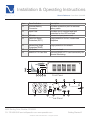
1
®
Owner’s Reference
Owner’s Reference PowerPack 1500 MKII
PowerPack 1500 MKII
4826 Sterling Drive, Boulder, CO 80301
PH: 720.406.8946 [email protected] www.psaudio.com
©2009 PS Audio International Inc. All rights reserved.
Introduction 1
®
Table Of Contents
Owner’s Reference PowerPack 1500 MKII
1. Introduction
1.1 Important Safety Instructions 1.2 System Description
1.3 Features
2. Installation and Operating Instructions 2.1 Unpacking & Inspection
2.2 Overview 2.3 Installation 2.4 Operation and Functionality Test 2.5 Manual Simulation of Power Outage for the UPS
2.6 Operating Parameter Setting 2.6.1 Configuration Mode 2.6.2 Display and Control Switch
2.6.3 End of configuration Mode 2.6.4 Setting of Parameters 2.6.4.1 Output Frequency Setting 2.6.4.2 Output Voltage Setting 2.6.4.3 AVR Buck Range Setting 2.6.4.4 AVR Boost Range Setting 2.6.4.5 Energy saving mode 2.7 Audible / Visual Indicators
2.8 Instructions for first time use
2.9 Instructions for battery replacement
3. Interface with PowerPlay
4. Warranty 5. Service
6. Troubleshooting
7. Specifications
4826 Sterling Drive, Boulder, CO 80301
PH: 720.406.8946 [email protected] www.psaudio.com
©2009 PS Audio International Inc. All rights reserved.
3-4
3
4
4
5-19
5
5-6
7-8
9-10
10-11
11
11
11
11
12
12
13
14
15
16
17-19
20
20
21
22-23
24-25
26-29
30
Table Of Contents 2
Introduction
®
Owner’s Reference PowerPack 1500 MKII
Important Safety
Instructions
Read these instructions
Heed all warnings
Follow all instructions
WARNING. TO REDUCE THE RISK OF FIRE OR ELECTRICAL SHOCK, DO NOT EXPOSE THIS
APPARATUS TO RAIN OR MOISTURE.
Clean only with a dry cloth.
Do not dispose of battery or batteries in fire. The batteries may explode.
The batteries used by this Uninterrupted Power System are recyclable. Proper disposal of the
batteries is required. The batteries contain lead and pose a hazard to the environment and human
health if not disposed of properly. Please refer to local codes for proper disposal requirement or
return the unit to a factory authorized Service Center for battery replacement or disposal.
Do not place flammable material on top of or beneath the component.
All PS Audio components require adequate ventilation at all times during operation. Rack mounting
is acceptable where appropriate.
Do not remove or bypass the ground pin on the end of the AC cord unless absolutely necessary
to reduce hum from ground loops of connected equipment. This may cause RFI (radio frequency
interference) to be induced into your playback setup. Removing or bypassing the ground pin on
any electrical component is potentially dangerous and should be avoided for safety reasons. A
polarized plug has two blades, one wider than the other. A grounding type plug has two blades
and a third grounding prong. All PS products ship with a grounding type plug. If the provided plug
does not fit into your outlet, consult an electrician for replacement of the obsolete outlet.
Protect the power cord from being walked on or pinched particularly at plugs, convenience
receptacles, and the point where they exit from the apparatus. Unplug this apparatus during
lightning storms or when unused for long periods of time.
When making connections to this or any other component, make sure all components are off. Turn
off all systems’ power before connecting the PS Audio component to any other component. Make
sure all cable terminations are of the highest quality.
THERE ARE NO USER-SERVICEABLE PARTS INSIDE ANY PS AUDIO PRODUCT. REFER ALL
SERVICING TO QUALIFIED SERVICE PERSONNEL
Please contact your authorized dealer, distributor, or PS Audio if you have any questions not
addressed in this reference manual.
4826 Sterling Drive, Boulder, CO 80301
PH: 720.406.8946 [email protected] www.psaudio.com
©2009 PS Audio International Inc. All rights reserved.
Introduction 3
®
Introduction
Owner’s Reference PowerPack 1500 MKII
1.1 System
Descriptions
The PowerPack 1500 MKII Battery Backup is a high performance solution for
Audio Video system protection. The True Sine Wave output and Voltage Regulation functionality makes the PowerPack 1500 MKII a better choice than Off-Line
or On-Line UPS.
The communication provided between the PowerPack and PS Audio’s PowerPlay and Audio Video Power Center line conditioners provides unparalled control
and monitoring.
1.2 Features
Line-Interactive Design Provides High Reliability and Efficiency
Intelligent Microprocessor Control
True Sine Wave Output with Less than 5% THD
Boost and Bucking Design Expands the Input Voltage Range
User Configurative Input Regulated Range and Output Voltage
Smart Battery Reminder
RJ11 Data/Fax Modem Connection Provides Surge Protection from Telephone
100BT RJ45 Connection Provides Surge and Spike Protection for Network
True RS232 & Contact Closure Signal for Power Management Software
Optional SNMP/HTTP Card Connectivity for Remote Monitoring
4826 Sterling Drive, Boulder, CO 80301
PH: 720.406.8946 [email protected] www.psaudio.com
©2009 PS Audio International Inc. All rights reserved.
Introduction 4
®
Installation & Operating Instructions
Owner’s Reference PowerPack 1500 MKII
2.1 Unpacking
& Inspection
Examine the packing carton for damage upon receipt. Once the UPS has been
removed from its shipping container, everything inside the package should be
inspected for damage that may have occurred while in transit. Notify the carrier
immediately if any damage is observed.
2.2 Overview
The box should include the following
•
•
•
•
UPS and Input Power Cord
User Manual
PowerPlay and Audio Video Power Center Communications Cable
Retain the packing for future use or disposal of property.
Item
1
2
3
4
5
6
7
8
9
10
11
Panel Indicator
Description
Main On Switch
(Silence/Test) “ | ”
Main Switch Off “ ”
Capacity Indicator
AC Buck Mode Indicator
AC Normal Indicator
AC Boost Mode Indicator
Backup Mode Indicator
Battery Replace Indicator
UPS Warning / Fault Indicator
Turn on UPS, Silence and Self-Test
RS232 Communication
Interface
Site Wire Fault Indicator
Displays Flashing/Continuous Red LED Transmits UPS status and receives control
Commands from the computer system. The
LED will illuminate upon hot and neutral polarity
reversal, or a bad ground connection.
Turn off UPS
LED bar shows load size and battery capacity
Continuous Amber LED display AC buck
Continuous Green LED display AC normal
Continuous Amber LED display AC boost
Continuous Green LED displays backup mode
Continuous Red LED displays battery failure
4826 Sterling Drive, Boulder, CO 80301
PH: 720.406.8946 [email protected] www.psaudio.com
©2009 PS Audio International Inc. All rights reserved.
Getting Started 5
®
Installation & Operating Instructions
Owner’s Reference PowerPack 1500 MKII
Item
12
13
Panel Indicator
External Battery
Connector
Input Fuse
Description
Provides connection port for external
battery cable
Provides circuit overload and fault
protection for the UPS and load
Connect to input power cord
Surge protection for fax, modem and
telephone
14
15
AC Inlet
Data Line Surge
Protection (RJ11)
16
Networking Surge
Protection (RJ45)
AC Outlet
SNMP/HTTP Card Slot
17
18
Surge protection for network
Connect to load
Optional SNMP/HTTP card connectivity for
Remote Monitoring.
3
9
1
2
4 5 6 8
7
Front Panel
12
14
18
EXT.BATTERY
OUT
SNMP/HTTP SLOT
AC INPUT
17
OUT
IN
FAX/MODEM
UPS OUTPUT
15
SITE
WIRE FAULT
NET
WORK
IN
INTERFACE
16
10
AC FUSE
13
5V Rear Panel
4826 Sterling Drive, Boulder, CO 80301
PH: 720.406.8946 [email protected] www.psaudio.com
©2009 PS Audio International Inc. All rights reserved.
Getting Started 6
11
®
Installation & Operating Instructions
Owner’s Reference PowerPack 1500 MKII
2.3 Installation
Before installation, please read and understand the following instructions:
Placement
The UPS must be installed in a protected environment away from heat-emitting
appliances such as a radiator or heat register. Do not install this product where
excessive moisture is present.
Ventilation
The location should provide adequate air flow around the UPS with one inch
minimum clearance on all sides for proper ventilation.
Charge the Battery
Your new UPS may be used immediately upon receipt. However charge loss
may occur during shipping and storage. So charging the battery for at least 8
hours is recommended to insure that the battery is fully charged.
To recharge the battery, simply leave the unit plugged into an AC outlet.
(This UPS will recharge in both the On and the Off status.)
Connect to AC
Make sure that the voltage and frequency are correct. Plug the UPS into a 2
pole, 3 wire grounding receptacle (wall outlet). Make sure the wall outlet branch
is protected. Avoid using extension cords if at all possible. If used, make sure
the extension cord is rated for 15 Amps.
For 220/230/240V versions: Swap the input power cord of the equipment to the
inlet of UPS. Use the power cord supplied with the UPS to connect from the
outlet of the UPS to your equipment.
Determining the Load:
1. Make a list of all equipment that requires protection.
4826 Sterling Drive, Boulder, CO 80301
PH: 720.406.8946 [email protected] www.psaudio.com
©2009 PS Audio International Inc. All rights reserved.
Getting Started 7
®
Installation & Operating Instructions
Owner’s Reference PowerPack 1500 MKII
2. Calculate the sum of all the V x A ratings. (Input voltage/current show on
the device or listed in the manual).
3. Ensure that the total VA rating does not exceed the rated capacity of the UPS.
If rated unit capacities are exceeded, an overload condition may occur and
cause the UPS unit to shut down or the circuit breaker to trip.
Connect the Load
Plug your primary equipment into the Battery Power Protected outlets. Leave
the power switches of the equipment in the “off” position for the moment.
Connect to PowerPlay
Use the enclosed RS-232 (DB9) to AppleTalk cable. Plug the 9-pin male end
into the UPS. Plug the 3-pin male end into the UPS port on your PS Audio
Power Conditioner.
• Note: Please check with your local dealer for the monitoring services.
4826 Sterling Drive, Boulder, CO 80301
PH: 720.406.8946 [email protected] www.psaudio.com
©2009 PS Audio International Inc. All rights reserved.
Getting Started 8
®
Installation & Operating Instructions
Owner’s Reference PowerPack 1500 MKII
2.4 Operation and AC Mode
Functionality Test The UPS delivers power to the loads derived from the utility and maintains
proper battery charge. It also regulates the output voltage to within a narrow
range and serves to isolate the load from surges and electrical noise brought by
the utility wiring.
On Battery Mode
The UPS operates on battery when the line voltage or frequency has fallen outside the limits. Users are alerted to this mode of operation by visual indicators.
The UPS provides power to the load from the battery and through its inverter
and the output voltage and frequency of the UPS are regulated within a narrow
band.
Function
Switch on
Test
Panel Indicator
Press and hold the main on switch on the front panel for more than 3
seconds until the “AC normal” green LED lights up. The UPS will perform a
self-test every time it is switched on.
Use the test function to check both the operation of the UPS and the condition of
the battery.
In AC operating mode, the level indicator will show the actual load connected to
this UPS normally. Press and hold the “I” switch on the front panel for more than
3 seconds. The level indicator will show the battery voltage for 10 seconds.
During this 10 seconds, if you press and hold the “I” switch for more than 3 seconds again, this UPS will enter into testing mode. The battery will provide power
to the load during this period. Testing mode will check the status of the battery
and operation of the UPS , last for 10 seconds and transfer back to normal status
automatically.
Testing mode can not be performed if the load connected is greater than 100% or
the charging voltage is lower than 26Vdc.
Alarm
Silence
In battery backup mode, the level indicator will show the battery voltage level.
Press and hold the “I” switch on the front panel for more than 3 seconds. The
level indicator will show the load level for 10 seconds.
4826 Sterling Drive, Boulder, CO 80301
PH: 720.406.8946 [email protected] www.psaudio.com
©2009 PS Audio International Inc. All rights reserved.
Getting Started 9
®
Installation & Operating Instructions
Owner’s Reference PowerPack 1500 MKII
Function
Switch Off
Cold Start/
Start on
Battery
2.5 Manual
Simulation of
Power Outage for
the UPS
Panel Indicator
Press and hold the main off switch for more than 3 seconds until the visual indicators turn off.
This UPS can be turned on even when AC is not present.
To test the backup function, you may unplug the power cord of the UPS or simply press the main on switch (silence/test) button on the front panel. The UPS
backup mode LED will turn on.
If the UPS is left to run continuously, it is a good idea to perform a periodic
functionality test on the unit. To perform this test simply press the test button on
the front of the UPS or unplug the power cord to the UPS to simulate the utility
blackout.
Observe that your equipment operates properly and uninterrupted during this period.
Plug the power cord back in if the function test was performed by unplugging it.
To conduct a simulation-test:
Switch the UPS on and wait for the Power On indicator to light up.
Then unplug the UPS from the AC outlet to simulate a utility failure.
When utility failure occurs, power is immediately supplied to your equipment from the
UPS battery.
If the utility power is not restored, the UPS will soon run out of battery power and will
shut itself down.
4826 Sterling Drive, Boulder, CO 80301
PH: 720.406.8946 [email protected] www.psaudio.com
©2009 PS Audio International Inc. All rights reserved.
Getting Started 10
®
Installation & Operating Instructions
Owner’s Reference PowerPack 1500 MKII
2.6 Operating
Parameter Setting
Restore electrical power to connected equipment by re-plugging the UPS power
cord into a wall outlet
2.6.1 Configuration Press and hold both the main on switch “I” and the main off switch “ ” on the
Mode
front panel for more than 3 seconds while the UPS is in the off status. The UPS
will now enter parameter configuration mode.
Level Indicator
Status Indicator
2.6.2 Display and
Control Switch
• When the UPS enters into the configuration mode, the turn on of six different
status indicator LEDs represent different parameter being programmed.
• Different parameter can be selected by pressing and holding the main off
switch “ ” for more than 3 seconds.
•Different settings can be selected by pressing and holding the main on switch
“I” for more than 3 seconds.
2.6.3 End of
Configuration
mode
• To Exit the configuration mode:
Press and hold both the main on switch “I” and off switch “ ” for more than 3
seconds.
4826 Sterling Drive, Boulder, CO 80301
PH: 720.406.8946 [email protected] www.psaudio.com
©2009 PS Audio International Inc. All rights reserved.
Getting Started 11
®
Installation & Operating Instructions
Owner’s Reference PowerPack 1500 MKII
2.6.4 Setting of
Parameters
Press and hold the main on switch “I” for more than 3 seconds to turn on the
2.6.4.1 Output
‘Frequency Setting right most LED. This indicates that the UPS is configured to work at 50Hz output
frequency.
Press and hold the main switch “I” again for more than 3 seconds to configure
the UPS to operate in the 60Hz mode.
Note: the battery backup mode output frequency will always follow the frequency of AC mains,
even if the internal presetting is different.
50Hz
LED on continuously
4826 Sterling Drive, Boulder, CO 80301
PH: 720.406.8946 [email protected] www.psaudio.com
©2009 PS Audio International Inc. All rights reserved.
60Hz
LED flashing
Getting Started 12
®
Installation & Operating Instructions
Owner’s Reference PowerPack 1500 MKII
2.6.4.2 Output
• Press and hold the main off switch
‘Frequency Setting “ ” to select the output voltage setting
mode.
• Press and hold the main on switch “I”
for more than 3 seconds to select different output voltage settings.
All Level LEDs off
Output = 115V (230V)
6th Level LED on
Output = 110V (220V)
5th Level LED on
Output = 120V (240V)
5th, 6th Level LED on
Output = 127V (208V)
4826 Sterling Drive, Boulder, CO 80301
PH: 720.406.8946 [email protected] www.psaudio.com
©2009 PS Audio International Inc. All rights reserved.
Getting Started 13
®
Installation & Operating Instructions
Owner’s Reference PowerPack 1500 MKII
2.6.4.3 AVR Buck AVR Buck Range sets the range at which the UPS will switch over to battery
when the utility presents an overvoltage situation.
Range Setting
• Press and hold the main off switch “ ” to select the AVR Buck Range Setting
mode.
• Press and hold the main on switch “I” for more than 3 seconds to select different AVR buck ranges.
AVR Buck Range mode
All Level LEDs off
AVR Buck = +25%
6th Level LED on
AVR Buck = +30%
5th Level LED on
AVR Buck = +20%
4826 Sterling Drive, Boulder, CO 80301
PH: 720.406.8946 [email protected] www.psaudio.com
©2009 PS Audio International Inc. All rights reserved.
Getting Started 14
®
Installation & Operating Instructions
Owner’s Reference PowerPack 1500 MKII
2.6.4.4 AVR Boost AVR Boost Range sets the range at which the UPS will switch over to battery
Range Setting
when the utility presents an undervoltage situation.
• Press and hold the main off switch “ ” to select the AVR Boost Range Setting
mode.
• Press and hold the main on switch “I” for more than 3 seconds to select different AVR boost ranges.
AVR Boost Range mode
All Level LEDs off
AVR Boost = -25%
6th Level LED on
AVR Boost = -30%
5th Level LED on
AVR Boost = -20%
4826 Sterling Drive, Boulder, CO 80301
PH: 720.406.8946 [email protected] www.psaudio.com
©2009 PS Audio International Inc. All rights reserved.
Getting Started 15
®
Installation & Operating Instructions
Owner’s Reference PowerPack 1500 MKII
2.6.4.5 Energy
Saving mode
• Press the main off switch “ ” to select the
energy saving setting mode.
• Press and hold the main on switch “I”
for more than 3 seconds to select different
energy saving modes.
All Level LEDs off
UPS in energy saving mode
4826 Sterling Drive, Boulder, CO 80301
PH: 720.406.8946 [email protected] www.psaudio.com
©2009 PS Audio International Inc. All rights reserved.
6th Level LED on
UPS in normal mode
Getting Started 16
®
Installation & Operating Instructions
Owner’s Reference PowerPack 1500 MKII
2.7 Visual
Indicators
Audible / Visual Indicators
Operating Status
AC buck mode
AC normal
AC boost mode
UPS fault
Backup mode
Backup time over 30
minutes
Energy saving mode
Battery is dead
Battery Capacity Indicators
LED1
LED2
LED3
LED4 LED5
Operating Status
LED6
Battery capacity= 100%
Battery capacity= 80%
Battery capacity= 60%
Battery capacity= 40%
Battery capacity= 20%
battery will run out
Note:
LED turn on continuously
— LED of
4826 Sterling Drive, Boulder, CO 80301
PH: 720.406.8946 [email protected] www.psaudio.com
©2009 PS Audio International Inc. All rights reserved.
LED flashing
X Any status
Getting Started 17
®
Installation & Operating Instructions
Owner’s Reference PowerPack 1500 MKII
Load Size Indicators (AC Normal)
LED1
LED2 LED3 LED4
Operating Status
LED5 LED6
Load size 20%
Load size 40%
Load size 60%
Load size 80%
Load size 100 %
UPS full load.
Remove the non-critical loads.
Load size 110%
Remove the non-critical loads
Load size 140%
Remove the non-critical loads or
UPS shuts off in 2 minutes
LED1
LED2 LED3 LED4
LED5 LED6
X
X
X
X
X
X
X
X
X
X
Note:
LED turn on continuously
Operating Status
UPS full load. Remove
the non-critical loads.
UPS overload. Remove
the non-critical loads
within 20 seconds
— LED of
LED flashing
4826 Sterling Drive, Boulder, CO 80301
PH: 720.406.8946 [email protected] www.psaudio.com
©2009 PS Audio International Inc. All rights reserved.
X Any status
Getting Started 18
®
Installation & Operating Instructions
Owner’s Reference PowerPack 1500 MKII
Abnormal Status Indicators
LED1 LED2 LED3 LED4 LED5 LED6 Operating Status
Output circuit short
Inverter over voltage
Inverter under voltage
Over temperature
Charger over voltage
Charger fault
Battery voltage abnormal
Battery is dead
Load size = 100%
Load size = 110%
Load size = 140%
Charger voltage abnormal
AC abnormal
Note:
LED turn on continuously
— LED of
LED flashing
4826 Sterling Drive, Boulder, CO 80301
PH: 720.406.8946 [email protected] www.psaudio.com
©2009 PS Audio International Inc. All rights reserved.
X Any status
Getting Started 19
®
Installation & Operating Instructions
Owner’s Reference PowerPack 1500 MKII
2.8 Instructions
for first time use
1.Remove the two screws from the vented door on the front panel.
2.Remove the vented door from the panel.
3.Remove the screws on left and right sides of battery drawer.
4.Slowly pull out the battery drawer.
5.Connect the black wire to the Negative (-) terminal of battery B (There may be a large
spark when batter connections are made).
6.Slowly push the battery drawer into the UPS.
7.Replace and tighten the screws on left & right sides of battery drawer.
8.Replace the vented door.
9.Replace and tighten screws to secure the vented door.
2.9 Instructions
for battery
replacement
1.Remove the two screws from the vented door on the front panel.
2.Remove the vented door from the front panel.
3.Remove the screws on left and right sides of battery drawer.
4.Pull out the battery drawer.
5.Connect batteries A & B in series by connect the Negative (-) terminal of battery A to
the Positive (+) terminal of battery B with the included battery connecting cable.
6.Put the two batteries inside the battery drawer.
7.Connect the red wire to the Positive (+) terminal of Battery A.
8.Connect the black wire to the Negative (-) terminal of Battery B.
(There may be a large spark when batter connections are made)
9.Slowly push the battery drawer into the UPS.
10.Replace and tighten the screws on left & right sides of battery drawer.
11.Replace the vented door
12.Replace and tighten crews to secure the vented door.
Battery A
+
Battery B
-
Battery drawer
Screws
4826 Sterling Drive, Boulder, CO 80301
PH: 720.406.8946 [email protected] www.psaudio.com
©2009 PS Audio International Inc. All rights reserved.
Getting Started 20
®
Interface with PowerPlay
Owner’s Reference PowerPack 1500 MKII
3. Interface with
PowerPlay
When connected with a PS Audio PowerPlay or Audio Video Power Center, the
UPS communications cable provides critical information to the power conditioner. In order to enable PS Audio’s revolutionary Intelligent UPS Management
Control and Configuration connect the RS-232 (DB9) end of the included communications cable into the PowerPack. Then connect the 3-Pin connector to the
UPS port of the PS Audio power conditioner. Finally plug the power cable for the
power conditioner into one of the outputs of the PowerPack.
Note: The Intelligent Management Control and Configuration is only available for
devices powered from the PS Audio power conditioner. When a PS Audio Power
Conditioner is connected it is not recommended to power any other devices
directly from the PowerPack.
PowerPlay
Connect Power play UPS to Interface connection on the UPS
PowerPack 1500 MKII
EXT.BATTERY
OUT
SNMP/HTTP SLOT
AC INPUT
UPS OUTPUT
IN
FAX/MODEM
OUT
SITE
WIRE FAULT
NET
WORK
IN
INTERFACE
AC FUSE
115V Rear Panel
4826 Sterling Drive, Boulder, CO 80301
PH: 720.406.8946 [email protected] www.psaudio.com
©2009 PS Audio International Inc. All rights reserved.
Getting Started 21
Warranty
®
Owner’s Reference PowerPack 1500 MKII
TERMS AND
CONDITIONS
Conditions
PS Audio provides a 1 year manufacturer’s warranty on the PowerPack 1500 MKII
component. This Warranty is for the benefit of the original purchaser and may not be
transfered to a subsequent purchaser of the product.
This Warranty is subject to the following conditions and limitations: the Warranty is void
and inapplicable if the product has been used or handled other than in accordance with
the instructions in the owner’s manual, abused, or misused, damaged by accident or
neglect or in being transported, or the defect is due to the product being repaired or
tampered with by anyone other than PS Audio or an authorized PS Audio repair center.
a. The product must be packaged and returned to PS Audio or an authorized PS
Audio repair center by the customer at his or her sole expense in the original
packing material. PS Audio will pay return freight of its choice for original
purchasers.
b. Return Authorization Number (RA Number) is required before any product
is returned to our factory for any reason. This number must be visible on the
exterior of the shipping container for PS Audio to accept the return. Units
shipped to us without a Return Authorization Number or without a visible RA
Number on the exterior of the shipping container will be returned to the sender,
freight collect.
c. RETURNED PRODUCT MUST BE ACCOMPANIED BY A WRITTEN
DESCRIPTION OF THE DEFECT.
Remedy
PS Audio reserves the right to modify the design of any product without obligation
to purchasers of previously manufactured products and to change the prices or
specifications of any product without notice or obligation to any person.
In the event the product fails to meet this Warranty and the above conditions have been
met, the purchaser’s sole remedy under this Limited Warranty shall be to return the
product to PS Audio or an authorized PS Audio repair center where the defect will be
repaired without charge for parts or labor.
4826 Sterling Drive, Boulder, CO 80301
PH: 720.406.8946 [email protected] www.psaudio.com
©2009 PS Audio International Inc. All rights reserved.
Warranty 22
Warranty
®
Owner’s Reference PowerPack 1500 MKII
MiscellaneousThis warranty does not cover the cost of custom installation, customer instruction, setup adjustments or signal reception problems.
This warranty does not cover cosmetic damage or any damage due to accident, misuse, abuse, negligence or modification of, or to any part of the Product, without initial express consent from PS Audio. This warranty does not cover damage due to improper operation or maintenance, connection to improper voltage supply, or attempted repair by anyone other than a facility authorized by PS Audio to service the Product.
Outside the US
This warranty is invalid if the factory applied serial number has been altered or removed from the Product.
To locate the servicer or dealer nearest you, or for service assistance or resolution of a service problem, or for product information or operation, call or email PS Audio.
ANY IMPLIED WARRANTIES RELATING TO THE ABOVE PRODUCT SHALL BE LIMITED
TO THE DURATION OF THIS WARRANTY. THE WARRANTY DOES NOT EXTEND TO ANY
INCIDENTAL OR CONSEQUENTIAL COSTS OR DAMAGES TO THE PURCHASER. Some
states do not allow limitations on how long an implied warranty lasts or an exclusion or
limitation of incidental or consequential damages, so the above limitations or exclusions may
not apply to you. This Warranty gives you specific legal rights, and you may also have other
rights that vary from state to state.
Inquiries regarding the above Limited Warranty may be sent to the following address: PS
Audio International, Inc., 4826 Sterling Drive, Boulder, Colorado 80301 ATTN: Customer
Service; Email: [email protected]; Voice 720-406-8946; FAX: 720-406-8967.
PS Audio has authorized distribution in many countries of the world. In each country, the authorized
importing retailer or distributor has accepted the responsibility for warranty of products sold by that retailer
or distributor. Warranty service should normally be obtained from the importing retailer or distributor from
whom you purchased your product. In the unlikely event of service required beyond the capability of the
importer, PS Audio will fulfill the conditions of the warranty. Such product must be returned at the owner’s
expense to the PS Audio factory, together with a photocopy of the bill of sale for that product, a detailed
description of the problem, and any information necessary for return shipment.
4826 Sterling Drive, Boulder, CO 80301
PH: 720.406.8946 [email protected] www.psaudio.com
©2009 PS Audio International Inc. All rights reserved.
Warranty 23
Service
®
Owner’s Reference PowerPack 1500 MKII
If you require
service in North
America
Obtain an RA
number
In the unlikely event there is a problem with your PS Audio component, please contact your
dealer, distributor, or the PS Audio corporate research center to discuss the problem before you
return the component to our facilities for repair. Products shipped to the corporate research
facilities will be refused and returned freight collect if not accompanied by a PS Audio Service
Department issued return authorization number (RA Number).
Return authorization numbers must be prominently displayed on the outside of the box and an
accompanying letter describing the problem and re-listing the RA number must be inside the
box to qualify for service.
If you are transferring your warranty, you must first contact PS Audio or your dealer or distributor
for details.
To contact the PS Audio Service Department:
Contact
information
If you are in the
United States
TELEPHONE
HOURS FAX
E-MAIL
WEBSITE 720-406-8946
Monday-Friday, 9:00 am to 5:00 pm MST
720-406-8967
[email protected]
http://www.psaudio.com
If you are in the United States use the following procedure:
1. Obtain a Return Authorization Number (R/A number) and shipping address from the PS
Audio Service Department.
2. Insure and accept all liability for loss or damage to the product during shipment to the PS
Audio factory and ensure all freight (shipping) charges are prepaid.
The product may also be hand delivered to the California or Colorado facilities if arrangements
with the Service Department have been made in advance. Proof of purchase will be required for
warranty validation at the time of hand delivery.
Use original
packing
Use the original packaging to ensure the safe transit of the product to the factory, dealer, or
distributor. PS Audio may, at its discretion, return a product in new packaging and bill the owner
for such packaging if the product received by PS Audio was boxed in nonstandard packaging or
if the original packaging was so damaged to the point it was unusable. If PS Audio determines
that new packaging is required, the owner will be notified before the product is returned.
To purchase additional packaging, please contact your authorized PS Audio dealer, distributor, or
the PS Audio Service Department for assistance.
If you are outside
the US
If you are outside the United States and require service you must contact your country’s dealer
or distributor for instructions. PS Audio warranties its products (see warranty section)
4826 Sterling Drive, Boulder, CO 80301
PH: 720.406.8946 [email protected] www.psaudio.com
©2009 PS Audio International Inc. All rights reserved.
Service 24
Service
®
Owner’s Reference PowerPack 1500 MKII
worldwide. Service for PS Audio products outside the United States is handled through your
country’s distributor or dealer.
1. Obtain a Return Authorization Number (R/A number) and shipping address from your dealer
or distributor’s Service Department.
2. Insure and accept all liability for loss or damage to the product during shipment to the dealer
or distributor’s Service Department and ensure all freight (shipping) charges are prepaid.
If you have
problems
If you feel your country’s dealer or distributor is either unwilling or unable to service your PS
Audio products, please contact our service department at [email protected] or at the above
contact numbers to discuss the situation.
Voltage changes
Voltage changes to match your country’s voltage and frequency requirements to your PS Audio
product are possible only through your dealer, your country’s authorized PS Audio distributor
or the factory. Units purchased outside your country of residence will not be changed to
the appropriate voltage unless prior arrangements have been made at the time of purchase.
Please refer any questions to your dealer or distributor or by contacting the PS Audio service
department.
Your serial
number
Your PS Audio product serial number is:
Your purchase
information
Please fill in the dealer or distributor’s information from where you originally purchased the unit.
Date of purchase
4826 Sterling Drive, Boulder, CO 80301
PH: 720.406.8946 [email protected] www.psaudio.com
©2009 PS Audio International Inc. All rights reserved.
Service 25
®
Troubleshooting
Owner’s Reference PowerPack 1500 MKII
6. Troubleshooting The TROUBLESHOOTING TABLE in the next page covers most of the difficulties
that you may encounter under normal working conditions. If the UPS fails to operate properly, please review the following steps before calling the repair center:
1. Is the UPS plugged into a proper working outlet ?
2. Is the line voltage within the rating specified?
3. Does the fuse on the rear panel need to be replaced?
Please do not open the metal cover.
There are no user serviceable parts inside.
The batteries contained in the UPS are recyclable.
The batteries contain lead and pose a hazard to the environment
and human health if not disposed of properly.
Caution: Do not open or mutilate the batteries. They contain an electrolyte
which is toxic and harmful to the skin and eyes.
A battery can present a risk of electrical shock and high short circuit current.
When replacing batteries, wrist watches and jewelry such as rings should be
removed. Use tools with insulated handles.
Note: Please note the following information when you call for service:
1. Model No. / Serial No.
2. Date of purchase
3. Full description of problem.
4826 Sterling Drive, Boulder, CO 80301
PH: 720.406.8946 [email protected] www.psaudio.com
©2009 PS Audio International Inc. All rights reserved.
Troubleshooting 26
®
Troubleshooting
Owner’s Reference PowerPack 1500 MKII
6.1 Troubleshooting
Abnormal Situation
Cause
Solution
UPS can not turn and
LED not lit
• Main on switch not pushed or
pushed less than 3 seconds.
•Battery voltage is too low.
• Press and hold the Main on switch for
more than 3 seconds.
• Recharge the battery for at least 4 hours.
UPS always at battery
mode
• Power cord loose.
• Re-plug the power cord firmly.
• Input fuse blown.
• Remove load and replace fuse with the
• Line voltage too high or two low.
same rating.
• Line frequency over range.
• Check input voltage.
• Check input frequency.
UPS is normal but the
computer won’t turn on.
• Computer input power cord is
loose or not connected.
• Reconnect computer input power cord.
Backup time is less than
the rating
• Battery is not fully charged or
battery is dead.
• UPS is slightly overloaded.
• Recharge the battery for 6 hours and re
test the backup time. If problem remains,
call for service.
• Remove the least critical load
Backup mode, the UPS
automatically turns off
after 2 minutes
• UPS is in green power mode
and UPS will automatically turn
off in 2 minutes.
• Connect to load.
• Disable green power mode.
AC fail, UPS automatic
turn off.
• Battery is not fully charged or
is dead.
• UPS is overloaded and shuts
down.
• Recharge the battery for 6 hours and retest the backup time. If problem re
mains, call for service
• Remove non-critical load and start the
UPS again and recharge the battery for
6 hours.
The UPS fault LED
flashes, LED6 is lit.
• UPS is at full load
• Remove the non-critical loads.
During AC fail, the UPS
fault LED flashes, LED 6
is lit.
• UPS is over loaded, UPS shuts • Remove non-critical loads and start the
down in 20 seconds in backup
UPS again.
mode.
4826 Sterling Drive, Boulder, CO 80301
PH: 720.406.8946 [email protected] www.psaudio.com
©2009 PS Audio International Inc. All rights reserved.
Troubleshooting 27
Troubleshooting
®
Owner’s Reference PowerPack 1500 MKII
Abnormal Situation
Cause
Solution
AC fail, the UPS fault LED UPS is overloaded, UPS
flashes, LED6 is lit.
shuts down in 20 seconds in backup mode.
Remove non-critical load and start the UPS again.
AC is normal, the UPS
fault LED flashes, LED6
is lit.
UPS is overloaded.
Remove the non-critical loads.
AC boost mode, the UPS
fault LED flashes, LED6
is lit.
UPS is overloaded and
UPS will automatically
turn off in 2 minutes.
Remove the non-critical loads.
Site Wiring fault LED is on Site wiring problem.
communication function.
Call an electrician to check your wiring.
Not working
LED 1,2,4 lit.
Wrong interface cable.
Purchase the correct one from your distributor.
LED 1,2 lit.
UPS output circuit short.
Check output circuit.
LED 1,3 lit.
UPS inverter.
Call for service.
LED 1,4 lit.
Inverter over voltage.
Call for service.
LED 1,5 lit.
• UPS inverter is under
voltage.
• UPS is over heated.
Remove the UPS to provide adequate air flow area,
or check fan of UPS.
LED 1,3,5 lit.
Call for service.
LED 1,2,5 lit.
Charger over voltage.
Call for service.
LED1,4,5 lit.
Charger fault.
Plug in AC power.
Battery voltage abnormal Refer to 4.2 instructions to replace batteries.
or the battery is dead.
It is suggested that the battery replacement should be conducted by an authorized
technician and with the same type and capacity of battery.
4826 Sterling Drive, Boulder, CO 80301
PH: 720.406.8946 [email protected] www.psaudio.com
©2009 PS Audio International Inc. All rights reserved.
Troubleshooting 28
®
Troubleshooting
Owner’s Reference PowerPack 1500 MKII
Capacity
1500 VA
EMI/RFI Noise Filter
Up to 60dB (@1MHz)
TEL/FAX
Surge
Suppression
Joules
Clamp Rating
Type
114 Joules
395V
RJ11 (one pair), 2C
Networking Surge
Suppression
Performance
Type
Up to 100 Base-T
RJ45 (one pair), 4C
Indicators
Front Panel LEDs
Line Normal (Green), Battery Backup (amber), Boost (amber), Buck
(amber), Battery Replacement (red), Fault (red), Overload (red),
Load/Battery Capacity (Green x5 pcs)
Rear Panel LEDs
Red Site Wiring Fault LED (15Vac Model only)
Fault Message
Display by Load/Battery Capacity LED(Greenx5pcs)
Audible Alarms
Battery Backup (every 4 seconds), Battery Backup over 30 minutes
(Every 15 seconds), Battery Low (Every Second), Overload (twice
per second), Fault (Continuously)
Safety
North America
Europe
CSA, UL1778
EN 60950, EN 50091-1-1
EMI
North America
Europe
FCC Part 15, Class B
EN55022, Class B/EN 5091-2, Class B
EMS
Worldwide
Environment
Ambient Operation
Audible noise
Physical
Dimension (D*W*H)
Net Weight
IEC 801-1, 2, 3, 4, 5/EN1, 2, 3, 4, 5
3000 Meters max Elevation 0~95% Humidity, Non-condensing 0~40 °C
455x420x89.6mm/17.9”x16.5”.3.5”
120VAC
230VAC
*Specifications subject to change without prior notice
4826 Sterling Drive, Boulder, CO 80301
PH: 720.406.8946 [email protected] www.psaudio.com
©2009 PS Audio International Inc. All rights reserved.
Troubleshooting 29
Specifications
®
Owner’s Reference PowerPack 1500 MKII
7. Specifications
Capacity
1500 VA
Topology
Line-interactive
Input
•Nominal Voltage
•Voltage Range
•Frequency
•Range
•Power Factor
•115V/230 Vac
•+/-25% (+/-20 or +/-30% Configurable)
•50/60Hz +/-5%
•>0.95 (full load condition)
Output
•Nominal Voltage
•Voltage Regulation
•Frequency Stability
•Wave form
•Power Factor
•Distortion
•Overload Capacity
•Transfer Time
•11 5Vac/230 Vac (100, 1 10, 120, 127V ac/208, 220, 230, 240 Vac Configurative)
•+10~15% (Line Mode typical), +3% (Battery back up mode)
•50/60Hz +/-0.5%
•True Sine Wave
•0.625 lagging to 1
• <5% (Linear Load)
•110%~140% for 20 sec. (Back up mode)
•>104% for 10 cycles (Back up mode)
•<4mS (typical)
•Type
•DC Voltage
•Backup
•Sealed, Maintenance-free Lead Acid
•24V dc
•0~25 Minutes for standard Series
•Recharge Time
•<4 Hours Recovery to 90% (typical)
Battery
•External Battery
•Yes
Connector
•Users Replacement •Yes
Power Line
Surge Suppression
•Joules
•Max Peak Current
•Clamping Rating
•Response Time
•741 Joules
•1300A
•1300A (UL 1449 TVSS Rating)
•Normal Mode=OnS, Common Mode<1Ns
4826 Sterling Drive, Boulder, CO 80301
PH: 720.406.8946 [email protected] www.psaudio.com
©2009 PS Audio International Inc. All rights reserved.
Specifications 30