1
E'S
MANUAL
MODELNOS.
247.885550
247.885680
®
Caution:
ReadandFollow
AllSafetyRules
andInstructions
BeforeOperating
ThisEquipment
5 AND 8 HORSEPOWER
24" AND 26" WIDTH
TWO STAGE
TRACK DRIVE
SNOW THROWERS
Assembly
Operation
CustomerResponsibilities
Serviceand Adjustment
RepairParts
n ,,,,,,,..............
iim
' u= '=,''=
i=,=1=11
i
=,,n=H,......................
SAFETY RULES
ii
=
i
,,m
==
...................
, ,1=_==
m
WARNING: TO REDUCE THE POTENTIAL FOR ANY INJURY, COMPLY WITH THE FOLLOWING
SAFETY INSTRUCTIONS. FAILURE TO COMPLY WITH THE INSTRUCTIONS MAY RESULT IN
PERSONAL INJURY.
_b
TRAINING
• Readthis owner'sguidecarefullyin its entiretybeforeattempting
to assembleor operatethis machine.Becompletelyfamiliarwith
the controlsand the properuseof this machinebeforeoperating
it. Keepthis manualin a safe placefor future and regular referonceandfor orderingreplacementparts.
e Neverallowchildrenunder14 yearsold to operatea snowthrower Children 14 years old and over should onlyoperate snow
thrower under close parental supervision Only persons well
acquaintedwith these rulesof safe operationshouldbe allowed
to useyour snowthrower,
• Noone shouldoperatethis unit while intoxicatedor whiletaking
medicationthat impairsthe sensesor reactions
° Keepthe area of operationclearof all persons,especiallysmall
childrenand pets
o Exercisecaution to avoid slipping or falling, especiallywhen
operatingin reverse
_
PREPARATION
o Thoroughlyinspectthe areawherethe equipmentis to be used
andremovealt door mats,sleds,boards,wires andotherforeign
objects
• Disengageall clutches and shift into neutrat before starting
engine
= Donot operateequipmentwithoutwearingadequatewinter outer
garments.Do not wearjewelry,long scarfsor otherlooseclothing which could become entangled in moving parts Wear
footwearwhichwill improvetooting on slipperysurfaces
= Beforeworkingwith gasoline,extinguishall cigarettesand other
sourcesof ignition Checkthe fuel beforestarting the engine
Gasolineis an extremelyflammablefuel. Do not fill the gasoline
tank indoors, while the engine is running, or untit engine has
beenatlowedto coo! at leasttwo minutes Replacegasolinecap
securelyand wipe off any spilled gasoline beforestarting the
engineas it may causea fire or explosion
• Usea groundedthreewire plug-infor al!units with electricdrive
motorsor electricstartingmotors.
g Adjust collectorhousingheight to clear gravelor crushedrock
surface
= Neverattemptto makeanyadjustmentswhile engineis running
(exceptwherespecificallyrecommended
by manufacturer),
• Let engine and machineadjust to outdoor temperaturebefore
startingto clearsnow
o Alwayswearsafety glassesor eyeshields during operationor
while performingan adustment or repair,to protect eyesfrom
foreign objectsthat may be thrown from the machine in any
direction
_OPERATION
8 Donot put handsor feet nearor underrotatingparts Keepclear
of dischargeopeningandaugeratall times
° Exerciseextremecautionwhenoperatingon or crossinggravel
drives,walks, or roads.Stay alert for hiddenhazardsor traffic..
Donot carrypassengers.
• After strikinga foreignobject,stop the engine,removewire from
spark plug, and thoroughly inspectthe snow thrower for any
damage Repairthe damagebeforerestartingand operatingthe
snowthrower
• If the snow thrower shouldstartto vibrateabnormally,stop the
engineandcheckimmediatelyfor thecause Vibrationis generally a warningof trouble.
• Stop enginewheneveryou leavethe operatingposition, before
uncloggingthe collectorlimpelier housing or dischargeguide,
and makingany repairs,ad ustments,or inspections Neverplace
your hand n the d schargeor co ector openngs Usea stick or
woodenbroomhandleto unclogthedischargeopening
* Takeall possibleprecautionswhenleavingthe unit unattended
Disengagethe collectodimpeller, shift into neutral, stop the
engine,and removethe key
• When cfeaning, repairing, or inspecting, make certain
collectodimpellerand aflmoving partshavestopped Disconnect
spark plug wire and keepawayfrom plug to preventaccidental
starting.
o Do not run engine indoors, exceptwhen starting engine and
transporting snow thrower in or out of building Open doors
Exhaustfumesare dangerous.
o Do not clear snow across the face of slope& Exerciseextreme
caution whenchangingdirection on slopes.Do not attempt to
clearsteepslopes.
• Never operatesnow thrower without guards, plates, or other
safetyprotectiondevicesin ptace
• Neveroperatesnow throwernear gtassenclosure,automobiles,
windowwells,drop off, etc, withoutproperadjustmentsof snow
thrower dischargeangle.Keepchildrenandpetsaway
= Donot overloadmachinecapacityby attemptingto ciearsnow at
too fast a rate.
o Neveroperatethe machineat high transportspeedson slippery
surfaces Lookbehindandusecarewhenbacking
'_ Neverdirect dischargeat bystandersor allowanyonein front of
unit.
• Disengagepowerto collector/impellerwhen transportingor not
in use.
° Useonlyattachmentsand accessoriesapprovedbythe manufaclurer of snowthrower (such as wheelweights, counterweights,
cabs,etc..).
= Neveroperatethe snow throwerwithout good visibility or light.
Alwaysbe sureof your footing and keepa firm hold on the handies.Walk,neverrun.
• Muffler and enginebecomehot and can causea burn. Do not
touch
MAINTENANCE
ANDSTORAGE
* Checkshearbolts, enginemountingbolts,etc., at frequentintervals for propertightnessto be sureequipmentis in safeworking
condition.
o Neverstore the machinewith fuel in the fueltank insidea build_
ing where ignition sourcesare present,such as hot water and
spaceheaters,clothesdryers,andthe like Allow engineto cooi
beforestoringin anyenclosure
o Alwaysreferto owner'sguide instructionsfor importantdetailsif
snowthroweris to bestoredfor an extendedperiod
= Run machine a few minutes after throwing snow to prevent
freezeup of collector/impeller
* Checkdutch controls periodicaliyto verifythey engageand disengage properly and readjust if necessary Refer to owner's
guidefor adjustmentinstructions
LOOK FOR THIS SYMBOL TO POINT OUT
IMPORTANT SAFETY PRECAUTIONS, IT
MEANSmATTENTION!!! BECOME ALERT!!!
YOUR SAFETY tS INVOLVED.
CONGRATULATIONS
on your purchase of a Sears
Craftsman snow thrower It has been designed, engineered
and manufactured to give you the best possible dependability and performance,
Should you experience any problem you cannot easily remedy, please contact your nearest Sears Service Center/
Department in the United States. We have competent, welltrained technicians and the proper tools to service or repair
this unit
Please read and retain this manual The instructions wilt
enable you to assemble and maintain your snow thrower
properly Always observe the "SAFETY RULES,"
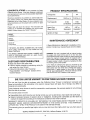
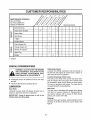
PRODUCT SPECIFICATIONS
Horsepower:
50
&0
Displacement:
1353 cu, in.
19,43 cu, in
Fuel Capacity:
2 Qts.
(Unleaded)
1 Gal°
(Unleaded)
Spark Plug
(Gap .030 in.):
J-SC or
Equivalent
J-SC or
Equivalent
.0125"
..0125"
Ignition Air Gap:
MODEL
NUMBER
SERIAL
NUMBER
MAINTENANCE
DATE OF
PURCHASE
THE MODEL AND SERIAL NUMBERS WILL BE FOUND
ON A LABEL ATTACHED
TO THE FRAME OF THE
SNOW THROWER,
YOU SHOULD RECORD BOTH SERIAL NUMBER AND
DATE OF PURCHASE AND KEEP 1N A SAFE PLACE
FOR FUTURE REFERENCE
CUSTOMER
RESPONSIBILITIES
e Read and observe the safety rules,
® Follow a regular schedule in maintaining, caring for
and using your snow thrower.
e Follow the instructions under"Customer
Responsibilities"
Owner's Manual
and "Storage"
sections of this
AGREEMENT
A Sears Maintenance Agreement is available on this
product. Contact your nearest Sears store for details
WARNING: This unit is equipped with an internal combustion engine and should not be used on or near any unimproved forest-covered, brush-covered or grass-covered land
unless the engine's exhaust system is equipped with a
spark arrester meeting applicable local or state laws (if any)
If a spark arrester is used, it should be maintained in effective working order by the operator
In the State of California the above is required by law
(Section 4442 of the California Public Resources Code)
Other states may have similar laws Federal laws apply on
federal lands, A spark arrester for the muffler is available
through your nearest Sears Authorized Service Center,
(See the REPAIR PARTS section of this manual,)
ONEYEAR LIMITED WARRANTY ON CRAFTSMANGASSNOW THROWER
For one year from the date of purchase, when this Craftsman Snow Thrower is maintained, lubricated and
tuned up according to the instructions in the owner's manual, Sears will repair, free of charge, any defect in
material and workmanship.
If this Craftsman snow thrower is used for commercial or rental purposes, this warranty applies for only 30 days
from the date of purchase.
This warranty does not cover:
•
•
Expendable items which become worn during normal use, such as skid shoes, shave plate and spark plugs.
Repairs necessary because of operator abuse or negligence, including bent crankshafts and the failure to
maintain the equipment according to the instructions contained in the owner's manual..
WARRANTY SERVICE IS AVAILABLE BY RETURNING THE CRAFTSMAN SNOW THROWER TO THE
NEAREST SEARS SERVICE CENTER/DEPARTMENT
IN THE UNITED STATES
THIS WARRANTY
APPLIES ONLY WHILE THIS PRODUCT IS IN USE IN THE UNITED STATES..
This warranty gives you specific legal rights, and you may also have other rights which may vary from state to
state
SEARS, ROEBUCK AND CO., D/817WA, Hoffman Estates, IL 60179
ii
......................
i
i
U,l,lllllil,,,ii
i Ul,ii
..............................
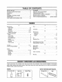
TABLE OF CONTENTS
,llji
_,
....................
SAFETY
iii, Ul,,i,iiiiiiiii
RULES
Hill
............................................................................
iii
PRODUCT
SPECIFICATIONS
............................................3
WARRANTY
............................................................................. 3
INDEX ..............................................................................................
4
ASSEMBLY
INSTRUCTIONS
.................................................
5
OPERATION
.............................................................................10
CUSTOMER
RESPONSIBILITIES
................................. 15
....................
iii
....
i
ii1,.,......................
i,u,
iii
i,,
M I"III'H
'1111'
STORAGE ..................................................................................17
SERVICE AND ADJUSTMENT
.........................................17
TROUBLE
SHOOTING ..........................................................21
REPAIR PARTS--SNOW
THROWER
..........................22
REPAIR PARTS--ENGINE
..................................................
31
PARTS ORDERING/SERVICE
..................
BACK COVER
2
ii,
i
,,
,i,ir,llr11,
ii,
i
i
, i,i1,111
ii i,
I
INDEX
i
r iii1,11,,,i,1,,i,i
,,111111
,
Ul,Ull
iii1,1,
,
i1,,1111111
i, i,,irr
A
i
lUI'M'
lU"IIII
F
Fuel .......................................................................................................
13
Adjustments:
Auger Clutch
20
L
Carburetor
20
Lubrication ............................................................................... 15
Shift Rod ......................................................................................
g, 20
M
Skid Shoes ...................................................................
9, 17
Maintenance:
Traction Drive Clutch ................................................................
9, 19
Agreement
3
Assembly Instructions:
Schedule ......................................................................................
15
Chute .............................................................................................................
6
Engine
16
Chute Crank ........................................................................... 7
Clutch Cables
8
O
Final Adjustments .................................................................. 9
Oil
13, 16
Handle .........................................................................................6
Operating Tips .....................................................................................
t5
Hardware Pack ................................................................................
5
R
Shift Rod ....................................................................................8
RepaidReplacement
Parts ...............................................................
20
Track Controls .....................................................................................
8
Responsibilities, Customer .................................................... 3
C
S
Controls .........................................................................................
t 0-11
Safety Rules
2
Customer Responsibilities
15
Spark Plug
16
E
Specifications
3
Engine:
Storage ........................................................................................17
Lubrication
t3, 16
T
Maintenance .....................................................................
16
Table of Contents .................................................................
4
Starting ...............................................................................................
14
W
Stopping ................................................................................. 12
Warranty ...................................................................................... 3
Storage
17
.................................................................................
................................................................
..............................................................................................
...................................................................................
....................................................................................
........................................................................................
..................................................................................
...............................................
.......................................................................................
................................................................................................
...................................................................................
...........................................................................................
|
u ....................................................
,,Jill
iii ,11,1111
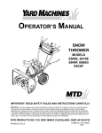
SNOW THROWER ACCESSORIES
i
iiiql
These
,11,
accessories
1,1,1,11
,,
were
=,
i
available
iii1,11111111
...................
iiil,,,lU,lUl,,
when the snow thrower
retail outlets, catalog and service centers.
model number of your snow thrower,.
Most Sears
ENGINE
Two Cycle Oil
was purchased.
stores
They
can order repair
i n,,lll
I
are also available
parts for you, when
II
at most Sears
you provide
SNOW THROWER MAINTENANCE
Gas Can
Spark
Plug
Scraper Bar
Belt
the
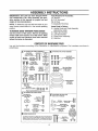
ASSEMBLY INSTRUCTiONs
i i,,i
iii
IMPORTANT: This unit has been shipped WITHOUT GASOLINE or OIL, After assembly, see operation section of this manual for proper fuel and
engine oil recommendations.
................................
IIIHII
II
IIIIIII1,111,111,11,1
111111,
Tools Required for Assembly:
1/2" Wrench*
(2) 7/16" Wrenches*
Pair of Pliers
*or Adjustable Wrenches
NOTE: To determine right and left hand sides of your
snow thrower, stand behind it in the normal operating
position°
Loose Parts in Carton:
(t) Handle Panel and Chute Assembly
TO REMOVE SNOW THROWER FROM CARTON
Cut the corners of the carton, Remove all packing
inserts. Roll snow thrower out of the carton, Make
(attached by cable)
(1) Right Hand Handle
(1) Left Hand HandJe
certain all parts and literature
before the carton is discarded.
(1) Chute Crank Assembly
(1) Shift Rod
have been removed
CONTENTSOFHARDWAREPACK
Lay out the hardware
parentheses
_
according
to the illustration for identification purposes,
ATTACHING THE HANDLE ASSEMBLY
Hex Bolts
{]CZ0(_ZZ0
5t16-18 x %3/4" _
_/_
Hex Nuts"
B_
ATTACHING
THE CHUTE ASSEMBLY
Hex Bolts
114-20 x 314" Long
(710-3015)
L_ _
_V_J
_.--1/4-20 Thread_
(736-0287)
_-_
Rex Bolts
5/16-18 X518"
Long (710-0538}
_
_"--_
Handle Tabs
(784-5599}
(_-_
Lock
'_J_.--Washers
Cupped
(736-011
5t16" I,D,g)
_
_)(_7,('_
Hex Lock Nuts
"=" _'-_
114" I.D,"-'-"_ [\'_vJ
(735-0270)Washers*
..-.
Hex Bolts*
1/4-20 x
1/4-20
Thread
_LJjJ
v
5116:18x []
1-1/2 Long
1 (710-12S0)
Bolts_
_
_
l_J
@
"-
Cupped Washers*_-._(F'_
51t6' I,D.
(736-0242)
HeX Nuts*
*May be preassembled
ATTACHING
Chute Range
Keepers
(731-0851
5116-18 Thread (712-0267)-=.O
_
Part numbers are shown in
_
)
_
on your unit.
THE CHUTE CRANK
Flat Washers
D_
3t8" LD, x 5/8" O.D,
Hex Bolt
ATTACHING THE.. SHIFT ROD
AND CLUTCH CABLES
tT-17,7_
Long
5f16-18 x 1-1t2"
(710-0442}
Ferrule
*_'(711-0677)
_
Hairpin
Ctips--'-_
(714-0104)
_)
_'_
Lock Washer
_
T
Cotter Pin
(714-0507)
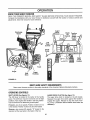
E_ AUGER SHEAR
/"_
_j"_-5116'
(736-011_)
5/16" LD, _'t'_
Hex Nut
5116-18 Thread----_{'C)]
(712-0267)
(_4-_Sprtng
Flat
LD.Washers
x 518" O.D°
(736-0264)
Washer
Hex Nuts
5116" LO,.
(Coma with
(736-0271)
Clutch Cables
Hex Lock Nuts
5t16-18 Thread
(712-0158)
BOLTS
tT"'-f7
The _ug_rs _re securedto the spiral shaft w_h _wohex boltsand hex
insertlocknuts.ff you hit a _orr_lgn
obje¢_0rtc_ I,_m,Ih_ snowthrowerIs
des]gffedsothat tha hex bo_tswill$he_r.Tworeplacementhex l_ffs and
nuls are providedf_ryour cQnvenlence
St_re}n_ 5_fep_aceortl_l_eeded
_
_._
_
_
NN
ri-'77
_._
Hex Botts
5116-18 X 1-1/2"
Long
(71o.o
o)
,=,=
i= ,,
=
=,,,=,,H,,, ,=,,,,,,i,,
,
ASSEMBLY INSTRUCTBONS
, i11,,,1
H
1111
l=,,,r
= ,
1],,_1,1
i
HOWTOSET-UPYOURSNOWTHROWER
WARNING:
_
MAKE
CERTAIN
THE
AND MOVED AWAY FROM THE SPARK
SPARK PLUG WIRE IS DISCONNECTED
PLUG BEFORE
ASSEMBLING
THE
SNOW THROWER.
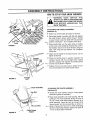
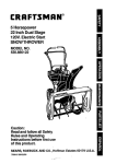
ATTACHING THE HANDLE ASSEMBLY
(Hardware A)
® Stretch out control cables and place on the floor.
® Place right handle in position with fiat side against
the snow thrower,r Secure bottom holes in handle
to snow thrower using hex bolts 5/8" long and lock
washers. See figure 1. Do not tighten at this time.
Bolt 1-3/4"
Long
O
FIGURE 1.
PIace handle tabs over the upper holes in handle,
so the curve in the handle tab matches the curve in
the handles. Secure to the snow thrower using hex
bolts 1-3/4" long and lock washers Do not tighten
at this time.
e Attach the left handle in the same manner, Do not
tighten at this time
Cupped
Washer
e Place the handle panel in position between the
handles, Secure with four carriage botts, cupped
washers (cupped side against the handle panel)
and hex nuts as shown in figure 2.
Hex
Jut
O
FIGURE 2,
Tighten the four hex bolts used to attach the bottom of the handles to the snow thrower frame.
Carriage
Bolt
, Assembly
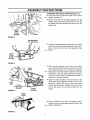
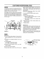
ATTACHING THE CHUTE ASSEMBLY
(Hardware
Hex Bolt
Hex Lock Nut
FIGURE 3.
Chute Flange
Keeper
B)
e Grease the chute opening using a multi-purpose
automotive grease or equivalent.
• Place chute assembly over chute opening, with the
opening in the chute assembly facing the front of
the unit, Place chute flange keepers beneath lip of
chute assembly. Insert hex bolt up through chute
flange keeper and chute assembly as shown in
-_----figure 3. Secure with hex lock nut,, After assembling
all three chute flange keepers, tighten then back off
1/4 turn to allow easier movement_
6
ATTACHING THE CHUTE CRANK (Hardware C)
• Insert hex bolt through the upper chute crank
bracket. See figure 4.
e Place the hex bolt into the hole provided in the left
handle. Secure with lock washer and hex nut. Do
not tighten until after attaching the other end of the
chute crank.
Upper
Chute
Crank
Bracket
/)
11
FIGURE 4.
Carriage Bolts
Hex Lock Nuts
e Loosen the carriage bolts and hex lock nuts which
secure the lower chute crank bracket to the extension on the left side of the chute assembly. See
figure 5.
Lower
Chute
Crank
Bracket
FIGURE 5.
_W
Flat
Chute
Crank
ashers
Cotter
Pin
Lower
Chute C
Bracket
Plastic
Bushing
FIGURE 6.
e Place one flat washer on the end of the chute
crank, then insert the end of the crank into the hole
in the plastic bushing in the chute crank bracket.
See figure 6, Place the other flat washer on the end
of the chute crank, and insert cotter pin into hole in
the end of crank, Secure by bending the ends of
cotter pin in opposite directions_
e Adjust the chute bracket so that the spiral on the
chute crank fully engages the teeth on the chute
assembly. Tighten the nuts on the lower chute
crank bracket securely, Tighten the hex bolt and
nut on the upper chute crank bracket on the
handle.
Cable
Guide
e Slip the cables that run from the handle panel to
the chute into the cable guide located on top of the
-._--- engine. See figure 7.
FIGURE 7,
.....=,
= IH'"H
...........
=H='
=l
'
'I=HH=
.....
ASSEMBLY iNSTRUCTIONS
=
=
=i Jill
ll', m'H,='=,',
=11
"H
l=' I'
IMPORTANT: Attach the shift rod and clutch cables as follows. THEN CHECK THE ADJUSTMENTS AS I
INSTRUCTED,
AND MAKE ANY FINAL. ADJUSTMENTS
NECESSARY BEFORE OPERATING YOUR
SNOW THROWER. Failure to follow the instructions may cause damage to the snow thrower.
Traction
Drive
Clutch
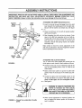
ATTACHING THE SHIFT ROD (Hardware
Shift
Lever
D)
e Insert the ferrule through the lower hote in the shift
lever beneath the handle panel from the right side°
Secure with flat washer and hairpin clip. See figure
8.
O
Lower ......
j
Hole in
Shift
Lever
Place the shift lever in the sixth (6) speed position
(all the way forward),
e Start threading the shift rod into the ferrule. Push
down on the shift arm assembly as far as it will go.
Thread shift rod into the ferrule until the end of the
Hairpin
Clip
shift red lines up with the hole in the shift arm
assembly. Secure with spring washer, fiat washer
and hairpin clip.
Make certain to check for correct adjustment of the
shift rod as instructed in the Final Adjustment section
before operating the snow thrower_
Washer_
Spring (_/_
Hairpin
Clip
i
Flat
Washer
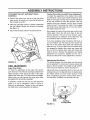
ATTACHING THE CLUTCH CABLES
The "Z" ends of the clutch cables are hooked into the
clutch grips on each handle., Attach cables as follows.
FIGURE 8.
e Thread the hex lock nuts (in hardware pack) all the
way up the threaded portion of the "Z" ends of the
clutch cables°
e Make certain each cable is in groove of cable roller
guides. Place the clutch grip in the raised (up) position.
e Thread the cable onto the threaded portion of the
"Z" and until there is no slack in the cable, but the
cable is NOT tight. Do not overtighten
cable
See figure 9
"Z" End
He]( Jam
Nut
Cable
is Straight
FIGURE 9.--Viewed
panel.
from underside of handle
WARNING: IF CABLE IS TIGHTENED SO
THERE IS TENSION
ON THE CABLE
WITH THE CLUTCH GRIP RELEASED,!
THE SAFETY FEATURES OF THE SNOW
THROWER MAY BE OVERRIDDEN.
t
I
I
I
e When correct adjustment is reached, tighten the
hex nut against the bottom portion of the cable to
lock it in position
ii
i
nnn,n
ASSEMBLY
,,
iNSTRUCTIONS
i
ATTACHING
CONTROLS
THE LEFT AND RIGHT TRACK
• Remove the screw from the top of the right hand
track control, Be careful not to lose the flat weld nut
that is inside the control.
• Place the right track control in position underneath
the right handle. Secure with screw just removed.
See figure 10
e Secure the left track control in the same manner,
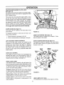
Traction Drive Clutch and Shift Lever Adjustment
To check the adjustment of the traction drive clutch
and shift lever, tip the snow thrower forward so that it
rests on the auger housing° First move the shift lever
all the way forward to sixth (6th) position. With the
traction drive lever released, turn the snow thrower
tracks by hand. They should turn freely. Then engage
the traction drive clutch grip and try to turn the tracks
The tracks should not move
Now release the traction drive clutch grip, and turn the
tracks again. Move the shift lever back to the fast
reverse position, then all the way forward again..
There should be no resistance in the shift lever, and
you should be able to turn the tracks by hand.
If you have resistance when moving the shift lever or
you are unabIe to turn the tracks by hand, loosen the
lock nut on the traction drive cable and unthread the
cable one turn If you are able to turn the tracks when
you engage the traction drive clutch grip, ioosen the
lock nut on the traction drive cable and thread the
cable in one turn_ Recheck the adjustment and repeat
adjustment as necessary.. Tighten the lock nut to
secure the cable when correct adjustment is reached
FIGURE '10.
Right
Track .._
Control
"I"_
FINAL ADJUSTMENTS
Auger Drive Clutch
To check the adjustment of the auger drive clutch,
push forward on the left hand clutch grip (depress the
rubber bumper). There should be slack in the cabie_
Release the clutch grip The cable should be straighL
Make certain you can depress the auger drive clutch
grip against the left handle completely..
If necessary, loosen the hex jam
cable in or out as necessary.
Recheck the adjustment° Tighten
the cable when correct adjustment
Adjusting the Skid Shoes
The space between the shave plate and the ground
can be adjusted° For close snow removal, place skid
shoes in the low position, Use middle or high position
when area to be cleared is uneven., See figure 11.r
Adjust skid shoes by loosening the four hex nuts and
carriage bolts and moving skid shoes to desired position. Make certain the entire bottom surface of skid
shoe is against the ground to avoid uneven wear on
the skid shoes Retighten nuts and bolts securely.
nut and thread the
Refer to figure 9.
the jam nut against
is reached.
H
FIGURE 11.
Carriage Bolts
OPERATION
i = i, = '='"=H",'H
' =,HI
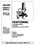
KNOW YOUR SNOW THROWER
READ THIS OWNER'S MANUAL AND SAFETY RULES BEFORE OPERATING YOUR SNOW THROWER.
Compare the illustrations with your snow thrower to familiarize yourself with the location of various controls and
adjustments. Save this manual for future reference
Discharge
Chute
Auger
Chute
Tilt
Control
Traction
Drivel
Auger
Clutch
Lock
Left
Track
Control
Chute
Crank
Right
Track
Control
Track
Auger
Skid
Shoe
Auger
Housing
FIGURE 12.
, ,= ,, ,,,,,H,
L
MEETS ANS! SAFETYREQUIREMENTS
Sears snow throwers conform to the safety standards of the American National Standards Institute.
OPERATING
CONTROLS
SHIFT LEVER (See figures 12)
The shift lever is tocated in the center of the handle
panel The shift lever may be moved into one of eight
positions, Run engine with throttle in the fast position,
Use the shift lever to determine ground speed°
AUGER DRIVE CLUTCH (See figure 12)
The auger drive clutch is located on the left handle.
Squeeze the auger drive clutch against the handle to
engage the augers_ Release to stop the snow throwing action. (Traction
drive clutch must also be
released.)
Forward---one of six speeds, Position number one (1)
is the slowest, Position number six (6) is the fastest
Reverse---two reverse (R) speeds, "R" closest to the
operator (atl the way back) is the faster of the two_
10
i i1,1
iiiiii1,1111r111
OPERATION
.........................
TRACTION DRIVE/AUGER
i i iiiii1,11,11
iiiiiiiiiiiii1,,,111
i ui,ii,
JI
CLUTCH LOCK
(See figure t2)
The traction drive clutch is located on the right handle,
Squeeze the traction drive clutch to engage the wheel
drive. Release to stop
This same lever also locks the auger clutch so you
can turn the chute crank without interrupting the snow
throwing process,. If the auger drive clutch is engaged
with the traction drive clutch engaged, the operator
can release the auger drive clutch (on the left handle)
and the augers wil! remain engaged. Release the
traction drive clutch to stop both the augers and wheel
drive (auger drive clutch must also be released).
Packed
Snow
CHUTE CRANK (See figure 12)
The chute crank is located on left hand side of the
snow thrower
FIGURE 13.
To change the direction in which snow is thrown, turn
chute crank as follows:
THROTTLE CONTROL (See figure 14)
The throttle control is located on the engine, It regulates the speed of the engine.
1_ Crank clockwise to discharge to the left.
2, Crank counterclockwise
to discharge to the right.
LEFT AND RIGHT TRACK CONTROLS
The left and right track controls are located on the
underside of the handles and are used to assist in
SAFETY IGNITION SWITCH (See figure 14)
The ignition key must be inserted in the switch before
the unit wil! start° Remove the ignition key when snow
thrower is not in use.
steering your snow thrower_ See figure 12, Squeeze
the right track control when turning right, squeeze the
left control when turning left. Operate your snow
thrower in open areas until you become familiar with
these controls.
Spark
Rope Starter
Handle
Box
CHUTE TILT CONTROL
The distance snow is thrown can be adjusted by
adjusting the angle of the chute assembly,, Move the
chute tilt control forward to decrease the distance,
toward the rear to increase See figure 12,,
TRACK LOCK LEVER
The track lock lever is located on the right side
snow thrower and is used to select the position
housing and the method of track operation. See
13. Move the lever to the right, then forward or
ward to one of the three positions,
Starter
Button
of the
of the
figure
back-
tg
Key
Transport--Raises
the front end of the snow thrower
for easy transport. May also be used on gravel driveways to clear snow and leave gravel undisturbed.
Throttle
Control
FIGURE 14.
Normal Snow--Allows the tracks to be suspended
independently for continuous ground contact
Packed Snow--Locks
the front end of the snow
thrower down to the ground for hard-packed or icy
snow conditions
HEAD LAMP (8 H.P° Only)
The head lamp is on whenever the engine is running°
'11
H=
,=,r=l
,,,H ......................
H,,,
,=
=,,,
OPERATION
.................................................
= HiM='
" MI'
BEFORE USING YOUR SNOW THROWER, AGAIN REFER TO THE "SAFETY RULES" AS SHOWN ON PAGE
2 OF THIS MANUAL ALWAYS BE CAREFUL,
The operation of any snow thrower can result in foreign objects being thrown into the
eyes, which can result in severe eye damage,, Always wear safety glasses or eye
shields before starting power tool operation or while performing any adjustments or
repairs, We recommend Wide Vision Safety Mask for over spectacles or standard
safety glasses available at Sears Retail or Catalog Stores.
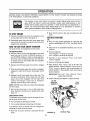
TO STOP ENGINE
® Move the tilt control to the rear to increase the distance.
o Remove the ignition key from the carburetor cover
on the engine (do not turn), See figure t4.
BEFORESTARTING
OIL
e Disconnect spark plug wire and move away from
spark plug to prevent accidental starting while
equipment is unattended_
e Only use high quality detergent oil rated with API
service classification SF or SG Use SAE 5W-30
oil
HOWTO USEYOURSNOWTHROWER
e SAE 10W is an acceptable
t0W-40)
The snow thrower is propelled by the two tracks,
TO ENGAGE DRIVE
substitute. (Do not use
® Oil sump capacity:
5 H,P. Engine 1-1/4 pints (19 ounces)
8 HP, Engine 1-5/8 pints (26 ounces)
® With the engine running near top speed, move shift
lever into one of the six FORWARD positions or
two REVERSE positions, Select a speed appropriate for the snow conditions that exist. Use the slower speeds until you are familiar with the operation
of the snow thrower.
• Maintain
oil level between
"FULL"
e Remove oil fill plug and dipstick.
e Wipe dipstick clean, insert it into oil fill hole and
tighten securely, Remove dipstick. If oil is not up to
"FULL" mark on dipstick, add recommended oil
POUR SLOWLY. Wipe dipstick ctean each time oil
level is checked
e Squeeze the left hand auger drive clutch to engage
it.
e White the left handle auger drive clutch is engaged,
engage the right hand traction drive/auger clutch
lock.
IMPORTANT:
o Release the left hand auger drive clutch only_ The
interlock mechanism should keep the left hand
auger drive clutch engaged until the right hand
traction
drive/auger
clutch !ock is released..
Release it and the drive motion will stop.
DO NOT FILL ABOVE
MARK ON DIPSTICK..
Oil Fill
Plug and_
Fuel
Tank
Dipstick X_k
e Set the track lock lever in one of the three positions: transport, normal snow or packed snow. See
figure 13.
DISCHARGE CHUTE
The direction snow is thrown can be changed by turning the chute control crank,,
e Turn clockwise to discharge to the left.
to discharge to the right.
The distance snow is thrown can be changed
adjusting the upper chute tilt control
"FULL"
e Instatl oi! fill plug and dipstick. Tighten securely,
NOTE: NEVER move shift lever without first releasing
the drive clutch.
• Turn counterclockwise
and "ADD"
marks on dipstick,,
by
• Move the tilt control forward to decrease the distance..
FIGURE t5.
12
Oil Drain Plug
OPERATION
=N''HH==r',,' = =
=
'I=",'"="'"HH'=......................................... ,'=, H=,'=,Hm=I
GAS
® Connect power cord to plug on snow thrower, then
to a three-hole, grounded 120-volt AC household
outlet.
rust or foreign particles. Never use gasoline that
may be stale from tong periods of storage in the
container Replace fuel cap.
WARNING: ALWAYS CONNECT POWER
CORD TO PLUG ON SNOW THROWER
FIRST, THEN PLUG THE OTHER END IN
THE HOUSEHOLD OUTLET. WHEN DIS*
CONNECTING,
ALWAYS
UNPLUG
FROM
THE HOUSEHOLD
OUTLET
FIRST.
WARNING:
DO NOT FILL CLOSER
THAN 1/2 INCH OF TOP OF FUEL TANK
TO PREVENT SPILLS AND TO ALLOW
FOR FUEL EXPANSION. IF GASOLINE
IS ACCIDENTLY SPILLED, MOVE SNOW
THROWER
AWAY FROM AREA OF
SPILL. AVOID CREATING ANY SOURCE
OF
IGNITION
UNTIL
GASOLINE
VAPORS HAVE DISAPPEARED.
e Push starter button to engage starter motor and
crank engine.
IMPORTANT:
Check the fuel level periodically to avoid running out
of gasoline while operating the snow thrower. If the
unit runs out of gas, it may be necessary to unclog the
unit before it can be restarted. Refer to Service and
Adjustment section..
THIS ELECTRIC STARTER IS NOT
EQUIPPED
WITH
A THERMAL
CUTOUT SWITCH. DO NOT CRANK
ENGINE FOR MORE THAN A TOTAL
OF 20 SECONDS WITHOUT ALLOWING ELECTRIC STARTER TQ COOL
DOWN
FOR 10 MINUTES,
OR
SEVERE DAMAGE TO ELECTRIC
STARTER CAN RESULT.
EXPERIENCE INDICATES THAT ALCO-
HOL BLENDED FUELS (CALLED GASOHOL OR
USING ETHANOL OR METHANOL) CAN ATTRACT
MOISTURE WHICH LEADS TO SEPARATION AND
FORMATION
OF ACIDS DURING
STORAGE.
ACIDIC GAS CAN DAMAGE THE FUEL SYSTEM
OF AN ENGINE WHILE IN STORAGE° TO AVOID
ENGINE
PROBLEMS,
THE FUEL
SYSTEM
SHOULD BE EMPTIED OR TREATED WITH FUEL
STABILIZER
BEFORE STORAGE FOR 30 DAYS
OR LONGER. USE FRESH FUEL NEXT SEASON.
SEE "STORAGE"
SECTION FOR ADDITIONAL
INFORMATION.
NOTE: If the starter motor runs but the engine does
not turn over, the starter gear is apparently covered
with ice and frozen. Place the unit in a warm atmosphere until the gear is free and the starter will
engage.
e After engine starts, release starter button, Allow the
engine to warm up for a few minutes Then move
choke gradually to OFF position° If engine falters,
return to ON position, then slowly move to OFF
position.
® Unplug the power cord from the household outlet,
then from the plug on snow thrower
NEVER USE ENGINE OR CARBURETOR CLEANER PRODUCTS IN THE FUEL TANK OR PERMA*
NENT DAMAGE MAY OCCUR.
USING THE RECOIL STARTER
e Make certain auger control handle is disengaged
(released).
TO STARTENGINE
® Insert ignition key into ignition switch. Do not turno
USING THE ELECTRIC STARTER
e To start a cold engine, move choke lever to ON
position if you are starting an engine which has
already been run for a few minutes, do not choke
• Make certain the auger control handle is disengaged (released)..
•
=
• To start a cold engine, push primer button one
time_ Use a firm push. This step is not necessary
when starting an engine which has been run for a
few minutes.
e Remove fuel cap and fill fuel tank with about 3
quarts of clean, fresh, lead-free grade automotive
gasoline DO NOT use Ethyl or high octane gasoline. Be certain container is clean and free from
WARNING:
H=
Insert ignition key into ignition switch Do not turn.
® To start a cold engine, push primer button two or
three times. Use a firm push. This step is not necessary when starting an engine which has been run
for a few minutes.
® To start a cold engine, move choke lever to QN
position. If you are starting an engine which has
already been run for a few minutes, do not choke.
13
= H ,=,
'H"H,'
====='I
NOTE: If the temperature is below 15°F,, additional
priming may be necessary for initiaJ start only.
® Grasp starter handle and pull rope out slowly, until
it pulls slightly harder° Let rope rewind slowly..
® Pull starter handle rapidly. Keep a firm hold on the
hand}e and allow it to rewind slowly. Do not allow
handte to snap back.
e If engine fails to start after 3 pulls on the starter
handle, prime engine two times and pull starter
handle again,
AVOID
INJURY
FROM
ROTATING
AUGERKEEP
HANDS,
FEET,
ANDCLOTHING
AWAY!
e After engine starts and begins to operate evenly,
move choke lever gradually to OFF position. If
engine falters, return to ON position, then slowly
move to OFF position_
OPERATINGTIPS
WARNING:
TEMPERATURE
OF MUF-I
® Use your snow thrower to remove fresh snow
before it is packed down by footprints or tire tracks
FLER AND SURROUNDING AREAS MAY I
EXCEED 150°F. AVOID THESE AREAS.
I
J
® Discharge snow in the direction the wind is blowing
whenever possible.
® Slightly overlap each previous swath°
e Snow up to about an 8 inch depth can be removed
easily by walking at a moderate rate° Slow your
pace for wet or deep snow.
® Run engine for a few minutes before stopping to
help dry off any moisture on the engine
14
Check Engine Oil
I'
=
uJ
Change Engine Oil
Z
',
_/
....
Service Air Cleaner
Z
I.u
1'
:
:
,
, .........
1'
............................
Spark Plug
#
Muffler
4
1' CHECK
GENERALRECOMMENDATIONS
Shifting Mechanism
Lubricate the shifting mechanism and pivot points on
the shift rod with engine oil at least once a season or
after every 25 hours of operation.,
WARNING: ALWAYS STOP THE ENGINE
AND DISCONNECT THE SPARK PLUG
WIRE BEFORE
PERFORMING
ANY
MAINTENANCE OR ADJUSTMENTS,
® Periodically
are tighL
check all fasteners
Traction Drive/Auger Clutch Lock
The cams on the ends of the control rods which inter-
and be sure they
lock the traction drive and auger drive clutches must
be lubricated at least once a season or every twentyfive hours of operation with grease, The cams can be
accessed beneath the handle panel
® Follow the Maintenance Schedule above
LUBRICATION
Gear Case
The gear case is lubricated with grease at the factory
and does not require checking,, If disassembled for
any reason, lubricate with 2 ounces of Shell Atvania
grease, part number 737-0168.
Gear Shaft
Lubricate the gear shaft with grease at least once a
season or after every 25 hours of operation,
IMPORTANT:
Keep all grease
friction wheel and drive plate.
and oil off of the
Bearings
Lubricate the auger bearings, wheet bearings and the
bearings on the side of the frame once a season with
light oil
15
,111,11,1,1
CUSTOMER
iiiir,lrl
ii
............................
i i
ii iii,
RESPONSiBiLiTiES
i
ii i, iiiiii1,1111
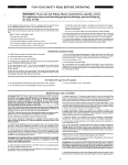
AUGERS
tighten
"FULL"
POUR
level is
The augers are secured to the spiral shaft with two
hex bolts and hex lock nuts° See figure 16. If you hit a
foreign object or ice jam, the snow thrower
is
designed so that the hex bolts will shear.
IMPORTANT:
If the augers will not turn, check to see if the hex bolts
have sheared. Two replacement hex bolts and hex
lock nuts have been provided with the snow thrower
For future use, order part number 710-0890 (hex bolt
5/16-18 x 1.5" long) and 7t2-0429 (hex insert lock nut
5/16-18 thread)..
i
iiiiiii
,i
securely_ Remove dipstick. If oit is not up to
mark on dipstick, add recommended
oil,
SLOWLY, Wipe dipstick clean each time oil
checked
DO NOT FILL ABOVE "FULL" MARK
ON DIPSTICK.
e Install oil fill plug and dipstick, tighten securely_
To Drain OIh
® Drain oil while engine is warm.
a, Remove oil drain plug. Refer to figure 15_ Catch
oil in a suitable container,
b. When engine is drained of all oil, replace drain
plug securely..
e Refill with fresh oil Refer to before starting in the
operation section,
Auger Bolts
e Replace dipstick.
SPARK PLUG
The spark plug should be cleaned and the gap reset
to .030" at least once a season or every 50 hours of
operation See figure t7 Spark plug replacement is
recommended at the start of each season. Refer to
engine parts list for correct spark plug type.
NOTE: Do not sandblast spark plug.. Spark plug
should be cleaned by scraping or wire brushing and
washing with a commercial solvenL
FIGURE 16.
ENGINE
ENGINE OIL
e
Only use high quality detergent oi! rated with API
service classification SF or SG Use SAE 5W-30
oil
• SAE 10W is an acceptable substitute.. (Do not use
lOW-40),,
Feeler Gauge
\
• Oi{ sump capacity:
5 HP, Engine 1-1/4 pints (19 ounces)
8 H°P, Engine 1-5/8 pints (26 ounces)
e Maintain
oil level between
"FULL"
and "ADD"
Spark Plug
marks on dipstick
• Remove oil fill plug and dipstick.
e Wipe dipstick clean, insert it into oil fill hole and
FIGURE t7.
16
nj
.................................
I= IH
,,,,,',,,,,,,,,,,I
=........................
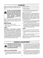
STORAGE
=,
,n,
• Drain the fuel tank_
Prepare your snow thrower for storage at the end of
the season or if the unit will not be used for 30 days or
more
WARNING:
NEVER
STORE
® Start the engine and let it run until the fuel lines and
carburetor are empty..
o Never use engine or carburetor cleaner products in
the fuel tank or permanent damage may occur.
MACHINE
OF BUILDING
WHERE FUMES MAY
WITH FUEL IN THE FLtEL TANK INSIDE
REACH AN OPEN FLAME OR SPARK,
OR WHERE IGNITION SOURCES ARE
PRESENT SUCH AS HOT WATER AND
SPACE
HEATERS,
FURNACES,
CLOTHES DRYERS, STOVES, ELEC*
TRIC MOTORS, ETC.
o Use fresh fuel next season..
NOTE: Fuel stabi!]zer is an acceptable alternative in
minimizing the formation of fuel gum deposits during
storage. Add stabilizer to gasoline in fuel tank or stor_
age container Always follow the mix ratio found on
stabilizer container Run engine at least 10 minutes
after adding stabilizer to allow the stabilizer to reach
the carburetor° Do not drain the gas tank and carburetor if using fuel stabilizer
NOTE: A yearly check-up by your local Sears Service
Center is a good way to make certain your snow
thrower will provide maximum performance for the
next season.
e Drain all the oil from the crankcase (this should be
done after the engine has been operated and is still
warm) and refill the crankcase with fresh oil
SNOWTHROWER
e If you have drained the fuel tank, protect the inside
of the engine as follows. Remove spark plug, pour
approximately 1/2 ounce (approximately one tablespoon) of engine oi_ into cytinder and crank slowly
to distribute oil.. Replace spark plugo
e Ctean the snow thrower thoroughly
e Wipe unit with an oiled rag to prevent rust (use a
light oil or silicone)_
ENGINE
OTHER
IMPORTANT:
IT [S IMPORTANT
TO PREVENT
GUM DEPOSITS FROM FORMING IN ESSENTIAL
FUEL SYSTEM PARTS SUCH AS CARBURETOR,
FUEL FILTER, FUEL HOSE, OR TANK DURING
STORAGE ALSO, EXPERIENCE INDICATES THAT
ALCOHOL BLENDED FUELS (CALLED GASOHOL
OR USING ETHANOL
OR METHANOL)
CAN
ATTRACT MOISTURE WHICH LEADS TO SEPARATION AND FORMATION OF ACIDS DURING STORAGE. ACIDIC GAS CAN DAMAGE THE FUEL SYSTEM OF AN ENGINE WHILE IN STORAGE,
WARNING:
ALWAYS STOP ENGINE
AND DISCONNECT SPARK PLUG WIRE
AND MOVE tT AWAY FROM SPARK
PLUG BEFORE
PERFORMING
ANY
ADJUSTMENTS OR REPAIRS.
e Do not store gasoline from one season to another°
e Replace your gasoline can if your can starts to rust,
Rust and/or dirt in your gasoline will cause problemso
e Store unit in a clean, dry area,, Do not store next to
corrosive materials, such as fertilizer,
NOTE: If storing in an unventilated or metat storage
shed, be certain to rustproof the equipment by coating
with a light oil or silicone
e To remove skid shoes, remove the four carriage
bolts, bellevitle washers and hex nuts which attach
them to the snow thrower. Reassemble new skid
I
I
I
I
I
shoes with the four carriage botts, betleville washers (cupped side goes against skid shoes) and hex
nuts. Make certain the skid shoes are adjusted to
be level.
SHAVEPLATEAND SKID SHOES
o To remove shave plate, remove the carriage bolts,
beHeville washers and hex nuts which attach it to
the snow thrower housing_ Reassemble new shave
plate, making sure heads of the carriage bolts are
to the inside of the housing Tighten securely
® The shave plate and skid shoes on the bottom of
the snow thrower are subject to wear. They should
be checked periodically and replaced when necessary.
17
SERVICE & ADJUSTMENT
i1,11,1
i
ii
ii
iii1,, iiiiiiii1,1111r,i
ii i1,11,,,i
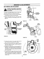
BELTREMOVALANDREPLACEMENT
WARNING:
DISCONNECT
THE SPARK I
PLUG WIRE FROM THE SPARK PLUG I
AND GROUND.
To remove and replace either the rear or front auger
drive belt, proceed with the following instructions.
Hex Bolts
Washers
Hex Nuts
• Disconnect the chute crank at the chute assembly
by removing the cotter pin and flat washer.
® Remove the plastic belt cover on the front of the
engine by removing two self-tapping screws.. See
figure 18,.
Frame
Auger
Assembly
FIGURE 19.
Auger
Housing
t
Cover
._Self-Tapping
Screws
FIGURE 18,
Frame
FIGURE 20.
Front
Auger
Drive
Belt
• Unthread the bottom of the auger cable from the
top of the cable, leaving the hex nut in place.
• Remove the six hex bolts, lock washers and hex
nuts which attach the auger housing assembly to
the frame. See figure 19.
® Separate the housing from the frame assembly by
standing in the operating position and lifting up on
the handles. The frame and housing will separate,
and the rear auger drive belt wilt come off the pulleys, See figure 20
Auger
e To remove the front auger drive bett, push the idler
pulley to the left, and lift front auger drive belt from
the front auger pulley.. See figure 21. Replace both
auger drive belts by following
instructions in
reverse order.
ulley
FIGURE 21,
18
...................................
SERVICE & ADJUSTMENT
iii
iilii
i iili
i
iiiiii iiiiiiiiiiim, = Hum,==rHm==,
i
iiiiii
i llilill
i ii illlli,ill
iililllli
i
lii
liliill
I
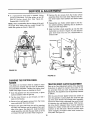
e If a replacement
drive belt is needed, follow
previous instructions. Pull idler pulley up and lift
belt off friction
wheel disc. See figure 22.
Reassemble in reverse order,
• Remove the six screws from the friction wheel
assembly (three from each side).. Remove the friction wheel rubber from between the friction wheel
plate,.
NOTE: When reassembling the two halves of the unit,
the auger drive cable must be routed through the
cable roller guides as shown in figure 22
• Reassemble new friction wheel rubber to the friction wheel assembly, tightening
rotation and with equal force.
the six screws
in
® Slide the friction wheel assembly up onto the shift
mechanism as shown in figure 24, and slide the
gear shaft back into the unit. Reassemble
in
reverse order.
Idler
Pulley
Cable
Roller
Guide
Hex Bolt
Lock Washer
Flat Washer
Cable
Friction
Wheel
Disc
FIGURE 22,
Track
FIGURE 23.
CHANGINGTHE FRICTION WHEEL
RUBBER
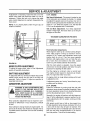
TRACTIONDRIVE CLUTCHADJUSTMENT
The rubber on the friction wheel is subject to wear
and should be checked after 25 hours of operation,
and periodically thereafter_ Replace the friction wheel
rubber if any signs of wear or cracking are found°
Refer to the Final Adjustment section of the Assembly
Instructions to adjust the traction drive clutch. If you
are uncertain that you have reached the correct
adjustment, the adjustment can be physically checked
as follows,.
o Drain the gasoline from the snow thrower, or place
a piece of plastic under the gas cap.
• Tip-the snow thrower
rests on the housing.
up and forward,
With the snow thrower tipped forward (be certain to
drain the gasoline or place plastic film under the gas
cap if the snow thrower has already been operated),
remove the frame cover underneath the snow thrower
so that it
• Remove four self-tapping screws from the frame
cover underneath the snow thrower
by removing four self-tapping screws. With the traction drive clutch released, there must be clearance
between the friction wheel and the drive plate in all
positions of the shift lever. With the traction drive
clutch engaged, the friction wheel must contact the
drive plate See figure 24
• Remove the gear shaft from the unit by removing
the bolts, lock washers and flat washers from each
side of the frame. See figure 23_ Hold the friction
wheel assembly, and slide the gear shaft out of the
unit toward the right hand side. Refer to figure 24.
19
SERV!CE & ADJUSTMENT
'UII=,I,
If adjustment is necessary, loosen the lock nut on the
traction drive cable and thread the cable in or out as
necessary Tighten the lock nut to secure the cable
when correct adjustment is reached,, Reassemble the
frame cover.
NOTE: If you placed plastic
certain to remove it
'n'Hn
IH=
5 H,P. ENGINE
Idle Speed Adjustment. This screw is located on top
of the carburetor and contacts the throttle To initially
pre-adjust this speed, back out the screw, then turn in
until the screw just touches the throttle lever, then turn
screw in 1 turn When the engine is run, the final idle
R.P.M can be adjusted with a tachometer
under the gas cap, be
Idle and Main Adjustment.
Turn these adjustment
screws in finger tight, then back them out to the preset figure on the chart.
Friction
Wheel
TECUMSEH
Gear Shaft
CARBURETOR
ENGINE
MODELS
PRE-SET
5H,Po
MAIN
1-1/4
PRE-SETS
PRE-SET
j
IDLE
1
Final Carburetor Adjustments
Allow engine to warm up to a normal running temperature. With engine running at maximum
recommended R.P,M, Ieosen main adjustment screw until
engine starts to cut out. Then turn screw opposite
direction until engine starts to cut out, Note the number of turns from one extreme to the other Loosen
Drive
Plate
screw to a point midway between the extremes
FIGURE 24_
After the main system is adjusted, move the speed
control lever to the idle position and follow the same
procedure for adjusting the idle system.
AUGER CLUTCHADJUSTMENT
To adjust the auger clutch, refer to Final Adjustment
section of Assembly Instructions.
Test the engine by running it under a normal load.
The engine should respond to load pick-up immediately An engine that "dies" is too lean
SHIFT ROD ADJUSTMENT
To adjust the shift rod, remove the hairpin clip and flat
washer which secure the shift rod to the shift arm
assembly
Refer to figure 8. Adjust as specified
Assembly instructions
An engine which ran rough before picking up the load,
is adjusted too rich
in
If adjustment seems too "touchy" check float for proper setting and for sticking
CARBURETORADJUSTMENT
8 H.P. ENGINE
WARNING: IF ANY ADJUSTMENTS
MADE TO THE ENGINE WHILE
ARE
THE
Preset the carburetor by turning both idle and main
adjustment screw closed (clockwise) fingertighL Open
the main adjustment screw 2 turns (counterclockwise)
and the idle adjustment screw 1-3/4 turns.
ENGINE IS RUNNING (E.G. CARBURETOR), KEEP CLEAR OF ALL MOVING
PARTS. BE CAREFUL OF HEATED SURFACES AND MUFFLER.
Generally, the engine wilt perform well with these settings If further adjustment is required, perform the following adjustments with the engine running and fully
warmed up.
Minor carburetor adjustment may be required to compensate for differences in fuel, temperature, altitude
or load
With speed control lever at idle or slow speed, turn
the idle adjustment screw slowly, clockwise 1/8 turn at
a time until the lean drop off point is reached (The
engine will miss and run erratically due to lack of fuel.)
Now turn the screw counterclockwise 1/4 to 3/8 turn
from that position This will be the best setting
Never attempt to change maximum engine speed, it is
pre-set at the factory and should be changed only by
a qualified service technician who has the necessary
equipment,
20
============,==
== n=,,=,
==========1=,1==
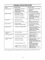
TROUBLE SHOOTING GUIDE
=
.................==
= ,==
= :::::::::::::::::::::::::
,nH,,=
Trouble
Possible Cause(s)
Corrective Action
Engine fails to start
1,,
2,
3.
4o
5.
1.
2.
&
4.
5,
Engine runs erratic
I Unit running on CHOKE,,
2_ Blocked fuel line or stale fuel.
Fuel tank empty, or stale fuel.
Blocked fuel line.
Key not in switch on engine_
Spark plug wire disconnected.
Faulty spark plug.
& Water or dirt in fuel system.
4. Carburetor out of adjustment.,
Loss of power
1. Spark plug wire loose
2_ Gas cap vent hole plugged,,
Engine overheats
oil level
low.
• Engine
Carburetor
not adjusted
properly
,n,,l=l,H=.=r
Fill tank with clean, fresh gasoline°
Clean fuel line
Insert key_
Connect wire to spark plug_
Clean, adjust gap or replace.
1, Turn choke knob to OFF position.
2. Clean fuel line; fill tank with clean
fresh gasoline.
3. Use carburetor bowl drain to drain
fuel tank,, Refill with fresh fuel,
4. Adjust carburetor. See separate
engine manual.
1,. Connect and tighten spark plug
wire.
2. Remove ice and snow from cap.
Be certain vent hole is clear,
1. Fill crankcase with proper oil.
2, Adjust carburetor. See separate
engine manual.
Excessive vibration
Loose parts or damaged impeller,
Stop engine immediately and
disconnect spark plug wire. Tighten
all bolts and nuts, Make all
necessary repairs If vibration
continues, have unit serviced by
Sears Service Center.
Hard to shift, or wilt
not shift
Shift rod misadjusted
Readjust shift rod., See Adjustment
section of this manual.
Unit fails to propel itself
•
Unit fails to discharge
t
Incorrect adjustment of drive clutch
2
Drive belt loose or damaged,
!., Auger shear boit broken
snow
2, Discharge chute clogged
3. Foreign object lodged in auger.
4. Incorrect adjustment of auger drive
clutch
5_ Auger drive belt loose or damaged
1. Adjust drive clutch, Refer to
Adjustment section_
2_ Replace drive belt, Refer to
Maintenance section.
Replace auger shear boil Refer to
Maintenance section,,
2o Stop engine immediately and
disconnect spark plug wire. Clean
discharge chute and inside of auger
housing.
,
Stop engine immediately and
disconnect spark plug wire.
Remove object from auger.
4, Adjust auger clutch. Refer to
Adjustment section,,
5, Replace auger drive belt, Refer to
Maintenance section,,
NOTE: For repairs beyond the minor adjustments listed above, please contact your nearest Sears Service Center.
21
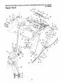
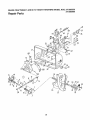
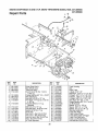
SEARS
CRAFTSMAN
5 AND 8 H.P. SNOW THROWERS
MODEL NOS. 247.885550
247.885680
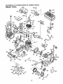
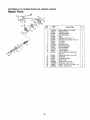
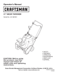
Repair Parts
/
6
1
I
14
52
\
43
22
_0
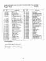
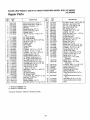
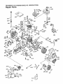
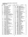
SEARS
CRAFTSMAN
5 AND 8 H.P. SNOW THROWERS
MODEL
Repair Parts
KEY
NO.
247.885680
PART
NOo
1
2
3
4
5
629-0058
684-0008
684-0022
684_0032A
684-0036
6
684-0037
7 710-0262
8 710-0442
9 710-0451
10 710-0538
tl
710-0776A
t2
710_1003
13 _710-1250
t4
t5 i710-3180
16 [71t-0653
17 i71t-0677
18 7t2-0116
19 712-0158
20 712_0267
21 712-0415
22 712-0429
23 712-3027
24 7'14-0104
25 714-0507
26 715-0!38
27 720-0201A
28
720-0232
725-1300
29
3O 726_0100
31
731-0851A
731-1300A
32
33 731-1313
t Modet247o885680
PART
DE'°"'P''0N
Light Harnesst
Shift Arm AsS'yr
Chute Crank Ass'y.
Handle Panel Ass'y.,
Engagement Handle Ass'y-R,H,
Engagement Handle Ass'y,--
NO.
34
35
36 t
I
/ 37 l
} 38 /
_ 40 !
Carriage
x.75 Lg. I
HexL-Bolt5/16q8x.62
Lg°
_
Hex AB-Tap Scr. 1/4 x ,62' Lg° _
Hex B-Tap Scr. #10-16 x .62" Lg._
Curved Carriage Bolt 5/16-!8 x /
1,,0" Lg.
,,
!
Hex Belt 1/4-20 x.,75 Lg,
_
Hex Bolt 5/16-18 x 1.75" Ig.
I
Clevis Pin 1" Lgo
/
Engagement Ferrule
/
Hex Ins. L-Nut 3/8-24 Thd,
/
Hex L-Nut 5/16-18Thd,
_
Hex Nut 5/!6-18 Thdo*
|
Studt
|
Hex Ins. L-Nut 5/16-18 Thd.
/
Hex FI L-Nut 1/4-20Thd
/
Cotter Pin 1.12" Lg.
|
Cotter Pin 3/32"
|
Roll Pin 1/8" O,D.
|
Chute Crank Knob
_
Shft Knob
|
Headlight 18 Wattt
|
Push Cap
|
Chute Flange Keeper
|
Lower Chute
|
Cable Guide
j
onlyo
*Common Hardware--May
NOTE: Specifications
notice or obligation,
NOS. 247.885550
be Purchased Locally.
subject
to change
without
23
44/
45 !
46 I
471
48/
49/
50|
52|
53 |
54|
55 |
56|
57 /
581
59/
6o/
61 /
62|
63/
64 i
65 i
66
67
68
69
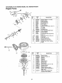
731-1317
731-1320
731-1327
731-1580
732-0145
732-0193
732-0746
735-0199A
736-0105
736-0119
736-0t40
736-0231
736-0242
736-0264
736-027t
736-0506
736-0509
741-0475
746-0896
746-0901
747-0798
747-0877
748-0362
748-0363
749-0908A
749_0909
784-0297
784-5594
784-5599
784-5604
784-5678
784-5679
784-5680
784-5681
784-5682
DESCRIPTION
Headlight Bezett
Upper Chute
Handle Panel (247885550)
Handle Panel (247885680)
Compression Spring 1" Lgo
Compression Spring .88" Lgo
Torsion Spring .8" Lg,
Rubber Bumper
Bell.-Wash .38" LD, x .88"
L-Wash. 5/16" I,D,,*
FL-Wash..385" x .62"OOD.
Washer .344" x 1.125" O.D.
BelL-Wash..345" I.D. x .88"
F!,,-Wash..33" x .63"O.D,,
Spr, Wash, .62" O.D.
Washer .286" I.Dox !o25" O°D.
Washer _35" LD x .72" OD.
Plastic Bushing. 38" ID.
Chute Control Cable w/Clip
Chute Control Cable
Shift Rod
Cam Rod
Handle Lock Cam
Handle Lock Pawl
Handle---R H
Handle--LH,
Shift Handle
Cable BrkL
Handle Tab
Chute Tilt Handle
Chute Crank BrkL Reinforce
Handle Supped BrkL--L H,,
Handle Support Brkto--R.H.
Handle Support Brkt.--L,H_
Handle Support Brkto--R.H.
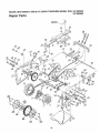
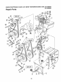
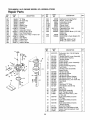
SEARS
CRAFTSMAN
5 AND 8 H.P. SNOW THROWERS
MODEL
NOS. 247.885550
247.885680
Repair Parts
43
57
3O
42
52
62
•
®
33
65
63
62
24
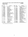
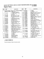
SEARS
CRAFTSMAN
5 AND 8 H.P. SNOW THROWERS
MODEL NOS. 247.885550
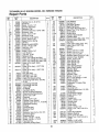
Repair Parts
KEY
NO,
247.88 e80
PART
NO.
2
3
4
51
6
7
8
9
10
I'I
12
13
14
15
17
18
19
20
21
22
23
24
61840043
618-0044
7t 8-0188
74t -0542
Ztl-0912
713-0411
/'15-0247
716-0114
716-0115
717-1209
7!7-1210
717-1211
736-0336
736-0502
618-0063
716-0185
684-0042
684-0008
684-0014
684-0031
710-0t 18
7t0-0502A
25
710-0642
26
710-0653
27
710-0788
28
710-1017
30 71'1-0911
31 711-0944
33 i712-0287
DESCRIPTION
KEY
PART
NO,
NO.
34 712-0298
35_ 713-0267
RH Dog Ass'y,
Loll. Dog Ass'y,
Carrier
5/16" Dowel Pin
Drive Shaft
12 Tooth Sprocket
Spring Pin 3/16" Dia. x 1" Lg
Snap Ring .56" Dia.
Snap Ring ,625" Shaft
12 Tooth Gear
18 Tooth Gear
Ring
Gear5/8" I,D, x 1" O.D,
Fl-Wash,,
FFWash .57" IoD, x 1,t2" O.D,
Friction Wheel Brg. Ass'y,,
Retaining Ring 1o375" Dia. Shaft
Friction Wheel
Shift Arm Ass'y.
Shift Rod Ass'y,
Frame Ass'y,
Hex Bolt 5/16-18 x ,75" Lg,*
Hex L-Wash. TT-Tap Scr.,
3/8-16 x 1 ,,25" Lg.
Hex TT-Tap Scr 1/4-20 x 75"
Lg,
Hex Wash. Hd. Tap Scr
1/4-20 x .38" Lg
Hex Wash TT-Tap Scr.
1/4-20 x 1" Lg.
Torx Mach,, AB-Tap Scr,
1/4 x .62" Lg
Actuator Shaft
Drive Shaft
Hex Nut 1/4-20 Thd.*
*Common Hardware--May
be Purchased Locally,
25
36
37
39
40
41
42
43
44
45
46
47
48
49
50
51
52
53
54
55
56
57
58
59
60
61
62
713-0415
713-0437
732-0209
736-0119
736-0176
736-0329
738-0870
741-0563
741-0597
748_0234
750-0903
750-0904
756-0625
784-5590
784-5644
784-5646
784-5648
784-5658
746-0897
683-0023
746-0898
746-0900
736-3052
750-0920
716-0102
710-0599
63
64
65
66
784-5677
718-0240
735-0243
710-3007
DESCRIPTION
Hex Jam Nut 1/4-20 Thd,
#420 Chain--I/2 Pitch x 30 Links
(Endless)
11 Tooth Sprocket
#420 Chain--32 Links (Endless)
Extension Spring 2.03" Lg.
L-Wash, 5/16" I.D.*
FI-Wash, !/4" I,D, x .93" OD.
L-Wash. 1/4" ID,*
Shld. Bolt 5/16" Dia. x 35" Lgr
Ball Brgo w/Snap Ring
Hex Flange Bearing
Shld Spacer .,5"Di& x .27" Lg
Split Shld Spacer 269" Lg,
Split Shld. Spacer 1.77" Lg
Cable Roller
Shift Brkt Frame
Drive Cable Roller Brkto
Auger Cable Guide Brkt,
Frame Cover
Front Support Brkt. Guide
Auger Clutch Cable
Track Hub Ass'y
Drive Clutch Cable
Track Steer Cable wFFrigger
Fl-Wash..406" IoD, x 1" O.D,
Spacer 1.02" 1D, x 1.25" O,D,
Snap Ring
Hex Wash Hd, TT--Tap Screw
1/4-20 x ,5" tg,
Friction Plate
Friction Wheel Hub
Friction Wheel Rubber
Hex Wash. Tap Scr. ,38" Lg,
SEARS
CRAFTSMAN
5 AND 8 H.P. SNOW THROWERS
MODEL
NOS. 247.885550
247,885680
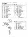
Repair Parts
55
55
75 27
22
75
26
SEARS
CRAFTSMAN
5 AND 8 H.P. SNOW THROWERS
MODEL
NOS. 247.885550
Repair Parts
KEY
PART
NO,,
1
2
3
4
5
6
7
8
9
10
11
12
13
14
15
16
17
19
20
21
22
23
24
25
26
27
28
29
30
3I
32
33
34
35
247.885680
KEY
DESCRIPTION
NO_
618-0120
6t8-0t21
719-0292
72t -0t 79
741-0339
719-0293
737-3000
NO.
Worm Drive Ass'y. Comp¢
Worm Drive Ass'y. Comp.l-€
Reducer Housing--LH
Oil Seal
Flange Bearing ..75" LD
Reducer Housing--RH
Grease Fitting
Hex TT-Tap Scr. 1/4.20 x 75"
Lg.
24" Auger Shaftt
26" Auger Shaft_¢ ,
#61 Hi-Pro Key 3/16 x 5/8" Dia,
Spiral Pin 1 25" Lg.
Impeller Shaft
Worm Gear
Thrust Collar
Oil Seal
FI-Wash_ .76" I.D x 1,5" O.D.
FI-Wash...5" I.D. x 1" O.D,
Fl-Wash..76" I.,D. x 149" O.D.
Flange Bearing .75" l.D,
Flange Bearing .503" t.D.
24" Auger Housing Ass'y 1
26" Auger Housing Ass'y.tt
Hex Bolt 5/16-24 x .75" Lg.*
Carriage Bolt 5/16-18 x _62" Lg,,
Carriage Bolt 5/16-18 x .75" Lg°
Hex Nut 5/16-24 Thd.*
Hex Nut 5/16-18 Thd*
L-Wash 5/16" LD.*
Bell-Wash 345" LD x ,.88" O.Do
Slide Shoe
24" Shave Platet
26" Shave Ptatett
Truss Mach,. Scr. 1/4_20 x ..5" Lg.
Hex Nut 1/4_20 Thd.*
Chute Adapter
Spdng Washer 1/4" ID
Hex Bolt 3/8-24 x 1.5" Lg (Gr. 5)
i710-0642
711-0908
711-0909
714-0388
715-0143
717-0526
717_0526
718-0186
721-0327
736-0351
736-0369
736-0445
741-0376
748-0106
684-0039
684*0040
710-0157
710-0260
710-0451
712-0123
712-0267
736-0119
736-0242
784-5580
784-5581
784-5579
710-0286
712-0287
731-1379
736_0175
710-0459
L,
¢ Mode1247o885550 only.
¢¢ Model247885680
only.
*Common Hardware--May
be Purchased Locally.,
27
36
37
38
40
41
42
43
44
45
46
47
50
51
52
53
54
55
56
57
59
60
64
PART
NO,
710-0812
712-0116
712-018I
712-0291
732-0611
736-0167
736-0329
738-0281
756-0178
784-5632
710-1087
741-0309
705-5 t 87A
715-0114
710-0890
712-0158
736-0188
741-0493A
684-0022
712-0429
714-0507
705-5189
705-5188
705-5193
705-5192
65
68
7O
75
76
78
736-0140
784-5647
05845A
741-0300
05931
684_0045
79
684-0046
80
81
82
710-0442
705-5225
721-0325
DESCRIPTION
Hex
Hex
Hex
Hex
Bolt 1/4-20 x ,75" Lg, (Gr 5)
Ins, L-Nut 3/8-24 Thd.
Top L-Nut 3/8-16 Thd,
L-Nut 1/4-20 Thd
^,, L _
Ext. Spring 3;_ u.
FFWash. 5/8' I.D, x !.25"
L-Wash. I/4" 1.D,*
Shld. Bolt ,625" Dia x o170" Lg.
FI-Idler 275" O_D.
Auger Idler Brkt.
Hex Bolt 5/16-18 x 5/8" Lg.
Ball Bearing ,75" LD,,
Blower Fan Ass'y
Spiral Pin 1,5" Lg.
Shear Bolt 5/16-18 x 1.5" Lg.
Hex Cent. L-Nut 5/!6-18 Thd,
FI-Wash. ,76" 1D. x 1,49"
Flange Bushing ,8" LD.
Chute Crank Ass'y.
Hex Ins. L-Nut 5/16-18 Thd.
Cotter Pin 3/32" Dia. x ,75"
Spiral Ass'y.--L H,I"
Spiral Ass'y.--RH,. (Not
Shown)t
Spiral Ass'y,--LH
1-1Spiral Ass'y,--R.H, (Not
Shown)l"t
FFWash..385" I,D, x ,,62" OD,
Lower Chute Crank BrkL
Bearing Housing
Plastic Bearing w/Fiats
Bearing Housing
Plate Reinforcement Ass'y.-LH.
Plate Reinforcement Ass'y-R.H,
Hex Bolt 5/16-18 x 1.5" Lg.
Chute Reinforcement Ass'y
Plug
SEARS
CRAFTSMAN
5 AND 8 H.P. SNOW THROWERS
MODEL NOS. 247.885550
247.885680
Repair Parts
/
/
28
52
SEARS
CRAFTSMAN
5 AND 8 H.P, SNOW THROWERS
MODEL
Repair Parts
KEY
NO,
1
PART
NOo
i HSSK50-67353N
' HMSKS0-1555245
2 !71040599
3 731-t324
4 i7t4-0133
1714-0122
5 710-3166
6 656-0009
7 710-0342
8 _756-0313
9 732-0264
10 712-0181
11 710-0230
12 736-0329
13 684-0021
14
15
16
17
18
19
20
21
22
712_071t
736-0105
714-0474
i736-0160
748-0190
,05896
i748-0234
_736-0119
i710-0117
M710-0604
23 i754-0343
754-0346
24 '732-0339
732-0710
25 _756-0959
26 i756-0569
t Model247.885550
t¢ Model247,885680
247.885680
DESCRIPTION
KEY
PART
NO.
NO,
27 I 754-0431
754-043O
281 710-0627
291 736-0242
30 1 736-O505
31 736-0507
32t 756-0967
331 710-0696
34 1 736-0331
351 736-0247
361 748-0360
37 i 756-0178
381 712-0116
39 t 710-0459
401 738-028!
41 784-5632
42 1 736-0t74
431 732-0611
44 1 710-08t2
451 712-0287
46 } 712-0291
47 I 710-1017
Engine--Tec. HSSK50-67353Nt
Engine--Tec,
HMSK80-155524511
HexWash Hd_TT-Tap Scr_
1/4-20 x 5" Lg,
Belt Cover
Sq,-Key 3/16 x 1.5" Lgl't
Sq,-Key 3/16 x ,75" Lg.t t"
Hex Patch Bolt 5/16-24 x
Lg.
(Gr. 5)
Friction Wheel Disc Ass'y.
Hex Bolt 3/8-16 x 1.25" Lg
F!-Idler 2,12" O.D.,
Ext. Spring 25" Lg,
Hex Top L-Nut 3/8-] 6 Thd,,
Hex Bolt 1/4-28 x 5' Lg,
L-Wash_ 1/4" IoD,*
Friction Wheel Support Brkt
Ass'y,
Hex Jam Nut 3/8-24 Thd.
Bell-Wash..38" I.D. x 88" O.D
Cotter Pin 1/8" x .75" Lg.
Fl-Wash..531" IoD, x .93" OD
Spacer .508" I.Dox .75" O,D,
Drive Clutch Idler Bracket
48 i 784-5658
491 710-0502
Shl& Spacer ,.5" Di& x 27" Lg
L-Wash. 5/16 I.D*t
Hex Bolt 5/16-24 x 1" Lg tHex Wash Hd. Tap Scr, 5/16-18
x .62" Lg.tt
"V"-Beltt
"V"-Beltl-t
Extension Springt
Extension Springl't
2" Dia. Pulley
3/8 "V'LPuttey Half
501 738-0870
51 712-0298
52 t 7!0-0788
53 { 710-1087
710-0602
541 736-0159
55 I 732-0705
561 711-0953
only,
only.
*Common Hardware--May
NOS, 247.885550
be Purchased Locally
29
DESCRIPTION
"V"-Beltl"
"V"-Beltl"t
Hex 5/16-24 x .75" Lg,
Bell-Wash..345" I.D_ x .88" OD,,
FI-Wash, .34" I.D., x 1.,5" O D.
Brg Retaining Washert
Auger Pulley
Hex Bolt 3/8-24 x .88 Lg,,
Bell-Wash .39" I.D. x 1.13" O.D
Fl-Wash. _406" IDo x 1,25" O.D.
Adapter Pulley
Fl-ldler 2.75" O.D.
Hex Ins, L-Nut 3/8-24 Thdo
Hex Bolt 3/8-24 x 1 5" Lg. (Gr, 5)
Shld. Bolt .625" Diao x 170" Lg.
Auger Idler Brkt.
Wave Wash. ,66" LD,, x ,88"
Exto
3 6" hg-5".7
Hex Spring
Bolt 1/4-20
x
Lg,, (Gr. 5)
Hex Nut 1/4-20 Thd*
Hex L-Nut 1/4-20 Thd.
Torx Mach, AB-Tap Scr,
1/4 x .62" Lg.
Front Support Brkt,, Guide
Hex L-Wash. TT-Tap Scr, 3/8-16
x 1 25" Lg.
Shldo Bolt 5/16" Dia., x .35" Lg
Hex Jam Nut 1/4-20 Thd.
Hex Wash. Hd. TT-Tap Scr,
1/4-20 x 1" Lgo
Hex Bok 5/16-18 x 5/8" Lg.l"
Hex Wash, Hd, Tap Scr
5/16-18 x 1" Lg,,¢lFI-Wash .349" I.D, x ,879" OD.
Cable Control Wire
Engine Studt
SEARS
CRAFTSMAN
5 AND 8 H.P. SNOW THROWERS
MODEL
Repair Parts
KEYi
NO, i
PART
NO.
4__
!
DESCRIPTION
!
1
2
3
4
631-0002
631-0004
683-0024
710-1233
5
6
7
8
741-0339
684-0024
710-0157
7!0-0604
9
710-0459
t0
11
12
13
14
15
16
17
18
710-1227
710-1230
710-1231
711-0941
712-0158
712-0214
712-0346
71240429
713-6115
NOS. 247.885550
247.885680
KEY
NO.
19
20
21
22
23
24
25
26
27
28
29
3O
31
32
33
34
35
36
37
38
39
Drive Wheel Ass'y.
Idler Wheel Ass'y,
Track Hub Ass'y
Oval C-Sunk Hd. Scr, 10-24 x
t ,375" Lg.
Flange Bearing 3/4" ID, x 15/16"
Idler Axle Ass'y.
Hex Bolt 5/16-24 x ,75" Lg.
Hex Wash. TT-Tap Scro 5/16-18
x ,62" Lg.
Hex Bolt 3/8-24 x 1.5" Lgo
(Special)
Bolt 5/t6-18 x 1,5" Lg,
Hex Bolt Ass'y. 5/16-18 x 9.81"
Eyebolt 5/16-18 x 3" Lg
Drive Axle
Hex CenL L-Nut 5/16-18 Thdo
Hex Cent. L-Nut 3/8-24 Thd.
Hex Ins. Jam L-Nut 1/2-20 Thd
Hex L-Nut 5/16-18 Thd
24 Tooth Sprocket
3O
PART
NO,
719_0295
720-0223
731-1292
736-0119
736-0255
736-0257
736-0287
736-0406
738-0155
741-0339
748-0353A
750-0499
750-0547
750-0909
784-5609
784-5639
784-5642
746-O9O0
684-0009
684-0038
712-0127
DESCRIPTION
Track Housing
Grip
Snow Track
L-Wash, 5/t6" I,D,*
Bell-Wash..515" I.D, x 1.14" O.D
Fl-Wash_ ,531" I,D, x 1,25" O D
Fl-Wash..793" I,D. x 1.24" O.Do
Fl-Wash. 3/8" I.D. x 7/16" O,D
Shld, Bolt ,437" Dia. x .162
Flange Bearing 3/4" IoDox 15/16"
Lift Shaft Drive
Spacer .5" I.D. x .78" Lg.,
Spacer ,628" I.D., x 5" Lg.,
Spacer .51" I.D. x 1,34" Lg,
Steering Cable Brkt,
Track Side Plate
Track Lockout Plate
Track Steer Cable w/Trigger
Track Pivot Rod Ass'y,
Track Lock Handle Ass'y,
/
Flat Weld Nut #10-24 Thd.
J
TECUMSEH
5 H.P. ENGINE
MODEL
NO. HSSK50-67353N
Repair Parts
310_/1
400
307//;
305/!
k..
!
396
t0A
285
93=_/
287 390
/,_
327
2!9
370A
420/_
31
TECUMSEH
5 H.P. ENGINE
MODEL NO. HSSK50-67353N
Repair Parts
CEY l
PART
NO,,
36469
26727
34171
5
30969
14 I
28277
15 I
31334
31510
16 l
17 I
31335
18 I 650548
31426
19 l
32600
20 I
33342
25 I
25A!
35883
26 1 650802
650926
26AI
35975
30 i
36073
4O i
4O
36074
36075
4O
36070
41
4l
36071
4!
36072
42
42
42
43
45
36076
36077
36078
20381
32875
46
48
49
5O
6O
61
62
63
64
64A
65
69
7O
75
76
8O
81
82
83
86
89
9O
92
93
100
101
1o2
I 103
I 110
32610A
27241
32654
35976
29745
34126
650760
28545
30063
8345
650128
27677A
34678A
27897
30318
30574A
30590A
30591
30588A
650488
610961
611199
650815
650863
34443A
61O118
650872
650814
35557
DESCRIPTZON
Cylinder (lncL 2 & 20)
Dowel Pin
Oil Drain Extension
Extension Cap
Washer
Governor Rod
Governor Lever
Governor Lever Clamp
Screw, 8-32 x 5/16"
Extension Spring
Oil Seal
Blower Housing Baffle
Baffle Extension
Screw, 1/4-20 x 5/8"
Screw, 8-32 x 21/64"
Crankshaft
Piston, Pin & Ring Set (Std.)
Piston, Pin & Ring Set (010" OS
Piston, Pin & Ring Set (,.020" OS
Piston & Pin Ass'y. (Std.)
(tnct. 43)
Piston & Pin Ass'y. (.0t0" OS)
(Incl. 43)
Piston & Pin Ass'y (.020" OS)
(IncL 43)
Ring Set (Std.)
Ring Set (.010" OS)
Ring Set (.020" OS)
Piston Pin Retaining Ring
Connecting Rod Ass'y (Incl.
46 & 49)
Connecting Red Bolt
Valve Lifter
Oil Dipper
Camshaft (BCR)
Blower Housing Extension
Grommet Mounting Bracket
Screw, 8*32 x 3/8"
Grommet
Screw, Torx T-30, 1/4-20 x 1/2"
Washer
Screw, t0-24 x 1/2"
Cylinder Cover Gasket
Cylinder Cover (Incl. 75,76 & 80
OIl Sea!
Camshaft Seal
Governor Shaft
Washer
Governor Gear Ass'y. (lncL 81)
Governor Spool
Screw, 1/4-20 x 1-1/4"
Flywheel Key
Flywheel (w/Ring Gear)
Belleville Washer
Flywheel Nut
Solid State Ignition
Spark Plug Cover
Solid State Mounting Stud
Screw, Torx T-15, 10-24 x 1"
Ground Wire
(EY
ITY. NOo
1
2
1
1
1
1
1
1
1
t
1
1
1
2
1
1
1
1
1
1
1
1
I
1
1
2
1
2
2
t
t
I
1
1
1
1
1
1
1
1
1
1
1
1
1
1
7
1
1
1
1
1
1
2
2
1
32
! PART
{ NO.
110AI
119 I
120 i
125 i
125 !
35285
36443
36441
29313C
29315C
126
126
32644A
32645A
127
129
130
131
135
150
t51
169
170
171
172
173
174
178
181
182
183
184
650691
650818
6021A
650694A
35395
31672
31673
27234A
27666
31410
34146
35350
30200
29752
650870
6201
34583
26756
185
186
200
33691
326£8
33858A
203
204
206
209
209_
215
219
220
222
223
224
260
262
267
268
274
275
277
285
287
290
291
292
295
298
300
301
305
31342
650549
610973
650139
30322
35440
34582
35438
28820
650664
33673A
35656A
29212
34212
30200
33670A
35771
650327
36476
650926
29774
30705
26460
35857
650665
35584
35355
35554
DESCRIPTION
Ground Wire
Cylinder Head Gasket
Cylinder Head (lncL 131)
Exhaust Valve (Std.) (Incl. 151)
Exhaust Valve (1/32" OS)
(lncl, t5t)
Intake Valve (Std.) (Incl 151)
Intake Valve (1/32" OS)
(IncL 15t )
Washer
Screw, 5/16-18 x 1-1/2"
Screw, 5/16-18 x 1-t/2"
Screw, 5/16-18 x 2"
Resistor Spark Plug (RJ19LM)
Valve Spring
Valve Spring Cap
Valve Cover Gasket
Breather Body
Breather Element
Valve Cover
Breather Tube
Screw, 10-24 x 9/16"
Nut & Lock Washer, 1/4-28
Screw, 1/4-28 x 1-t 1/16"
Screw, 1/4-28 x 7/8"
Choke Bracket
Carburetor To tntake Pipe
Gasket
Intake Pipe
Governor Link
Control Bracket
(lncL203,204,206,209 & 209A)
Compression Spring
Screw, 5-40 x 7/16"
Terminal
Screw, 8_32 x 1/2"
Lock Nut, 8_32
Control Knob
Choke Rod
Choke Knob
Screw, 10-32 x 1/2"
Screw, t/4-20 x 1-!9/32"
Intake Pipe Gasket
Blower Housing
Screw, 1/4-28 x 7/16"
Hold Down Bracket
Screw, 10-24 x 9/16"
Exhaust Gasket
Muffler (Incl. 274)
Screw, 1/4-20 x 2-t/2"
Starter Cup
Screw, 8-32 x 2t/64"
Fuel Line
Fuel Line
Fuel Line Clamp
Fuel Shut-Off Valve
Screw, 1/4-15 x 7/8"
Fuel Tank (tncL 292 & 301)
Fue! Cap
Oil Fill Tube
QTY,,
1
1
1
1
1
1
1
1
1
2
5
1
2
2
2
1
1
1
1
2
2
1
1
1
TECUMSEH
5 H.P. ENGINE
MODEL
NO. HSSK50-67353N
Repair Parts
PART
NOo
KEY
NOo
DESCRIPTION
KEY
NO.
QTY.
PART
NO.
DESCRIPTION
QTYo
+__
307
308
310
35499
35539
35556
34080
35392
35062
610973
35072
650257
36247
30063
650675
33344
570682
32180C
590574
327
328
3t3
329
335
338
340
342
342A
345
35O
351
355
"O" Ring
Fill Tube Clip
Dipstick
Spacer
Starter Plug
Switch Key
Terminal
Carburetor Cover
Screw, 8-32 x 5/16"
Fuel Tank Bracket
Screw, Torx T-30, 1/4-20 x 1/2"
Washer
Heat Baffle
Primer Ass'yo
Primer Line
Starter Handle
1
1
1
1
1
2
1
1
2
1
1
2
1
1
1
1
364
365
370
370A
370B
370C
380
390
396
400
420
KEY
NO.
2,_€
".
1
t
7
17 ',, .+++"+
"=.d!
_9_\2 °
21
60
_
+
Q,,_
29
Q
J
f
L
33
33333
650735
36261
35282
3650'I
34414
632107A
590646
33290D
36444
730226
PART
NO.
0
632107A
1
2
6
7
10
14
15
16
17
6316'15
631767
631036
650506
632108
631815
630735
631807
650417
18
20
21
22
23
25
27
28
29
3O
630766
631838
630766
630739
630740
631951
631024
632019
631028
631021
31
32
33
40
631022
27136A
27554
31839
41
630740
42
630739
43
630738
44
47
48
6O
27110
630748
63'1027
31840
Carburetor Cover Bracket
Screw, 10-24 x 3/8"
Lubrication Decal
Control Decal
Primer Decal
Warning Decal
Carburetor (Incl,, 184)
Rewind Starter
Electric Starter Motor (110 Volt)
(Optional)
Gasket Set
SAE 5W30 4-Cycle Engine Oil
(Quart)
RPM High 3450 to 3750
RPM Low 2000 to 2300
DESCRIPTION
Carburetor (Incl+ 184 of Engine
Parts List)
Throttle Shaft & Lever Assembly
Throttle Return Spring
Throttle Shutter
Shutter Screw
Choke Shaft & Lever Assembly
Choke Shutter
Choke Positioning Spring
Fuel Fitting
Throttle Crack Screw/Idle
Speed Screw
Tension Spring
Idle Mixture Screw
Tension Spring
Idle Mixture Screw Washer
Idle Mixture Screw "O" Ring
Float Bowl Ass'y, (IncL 32 & 33)
Float Shaft
Float
Float Bowl "O" Ring
Inlet Needle, Seat & Clip
(lncL 31)
Spring Clip
Bowl Drain Assembly
Drain Plunger Gasket
Main Adj+ Screw Ass'y (IncL
41 thru 44)
High Speed Mixture Screw
"O" Ring
High Speed Mixture Screw
Washer
High Speed Mixture Screw
Tension Spring
Bowl Nut Washer
Welch Plug, Idle Mixture Well
Welch Plug, Atmospheric Vent
Repair Kit
1
1
1
1
1
I
1
1
0
1
1
QTY.+
1
1
1
1
2
1
1
1
1
1
1
1
1
1
1
1
1
1
1
1
1
1
1
1
1
1
1
1
1
1
1
PART
NO°
33290D
31749
33522
33769
33524
35911
35461
35450
35912
35459A
35452A
590500
33441
35453
35454
35462
35456
650819
32450B
65O759
PART
NO.
DESCRIPTION
Electric Starter (110 Volt)
Retainer Ring
Spring Retainer
Anti-drift Spring
Nut & Gear
Thrust Washer
Drive End Cap Ass'y. (Incl.. 7)
"O" Ring
Armature
Housing Ass'y.
Brush & Spring Card Ass'y.
Thrust Washer
Ground Screw
Commutator End Cap Ass'y.
(tncL 7)
Switch Box Ass'y. (lncL 2t)
Case Bolt
Grounding Screw
Screw, 6-32 x 2-!/2"
Extension Cord (10'6")
Screw, Torx T-30, 1/4-20 x
23/32"
DESCRIPTION
QT_,,
1
1
1
1
1
1
1
2
1
1
1
1
1
1
1
2
1
2
1
QTY. !
t
590646
590599A
590600
590615
590601
590598
590616
590617
590645A
5906't9
590620
590647
590535
590574
34
Recoil Starter
Spring Pin (Incl. 4)
Washer
Retainer
Washer
Brake Spring
Starter Dog
Dog Spring
Pulley Ass'y. (lncl. 9 & 10)
Rewind Spring
Spring Cover
Starter Housing Ass'y.
Starter Rope (Length 96" x
9/64" dia)
Mitten Grip Handle (Not
included with starter)
1
1
I
I
1
1
1
1
I
1
I
I
2 I
2
1
1
1
I
TECUMSEH
8 H,P, ENGINE
Repair Parts
MODEL
NO. HMSK80-155524S
36_
298,_
!
13 IA',,,_
I
t
69
102
103
22,.
323
J
/
182
"275
26
315
/
90
1_370A
370C
200\
1c
209
327
93 ¸
/
390
287
35
TECUMSEH
8 H.P. ENGINE MODEL
NO. HMSK80-155524S
Repair Parts
PART
NO.
4
5
15
15A
15B
16
17
18
19
20
25
26
28
30
35
36
37
38
40
4O
40
41
35385
27652
650820
34171
30969
30699C
30700
65O494
33454
29916
650548
34663
35319
3646O
650561
30322
35980A
29826
29918
29216
29642
34552
34553
34554
34329A
41
34330A
4I
34331A
42
42
42
43
45
34332
34333
34334
27888
35373A
46
47
48
49
5O
60
61
62
63
65
69
70
71
75
76
8O
81
82
83
84
86
87
89
9O
650908
650882
34034
35374
35981
33273A
34126
65076O
28545
650128
35262
35445A
35377
35319
28926
31845
30590A
35378
30588A
29193
650833
650832
32589
611093
2
3 1
KEY
DESCRIPTION
Cylinder (IncL 2, 20 & 72)
Dowel Pin
Screw, 1/4_20 x 1/2"
Oil Drain Extension
Extension Cap
Governor Rod (Incl° 15A & 15B)
Governor Yoke
Screw, 6-40 x 5/16"
Governor Lever
Governor Lever Clamp
Screw, 8-32 x 5/16"
Speed Control Spring
Oil Seat
Blower Housing Baffle
Screw, 1/4-20 x 5/8"
Lock Nut, 8-32
Crankshaft
Screw, 10-32 x 3/4"
Lock Washer
Lock Nut, 10-32
Retaining Ring
Piston, Pin & Ring Set (Std.)
Piston, Pin & Ring Set (r010" OS
Piston, Pin & Ring Set (.020" OS
Piston & Pin Ass'y (Std.)
(tnct. 43)
Piston & Pin Ass'y. (.010" OS)
(lncL 43)
Piston & Pin Ass'y.. (O20" OS)
(Incl. 43)
Ring Set (Std.)
Ring Set (.010" OS)
Ring Set (.020" OS)
=iston Pin Retaining Ring
Connecting Rod Ass'y_ (1nct.46,
47,49)
Connecting Rod Bolt
Connecting Rod Bolt
Valve Lifter
Oil Dipper
Camshaft (MCR)
Blower Housing Extension
Grommet Mounting Bracket
Screw, 8-32 x 3/8"
Grommet
Screw, t0-24 x 1/2"
Cylinder Cover Gasket
Cylinder Cover (lncl. 71,75 & 80
Crankshaft Bushing
Oil Seal
Camshaft Seal
Governor Shaft
Washer
Governor Gear Ass'y. (Inct. 8'1)
Governor Spool
Retaining Ring
Screw, 1/4-20 x t-3/16"
Screw, 1/4-20 x 1-11/16"
Flywheel Key
Flywheel (w/Ring Gear)
NOo
92
93
100
101
102
'103
110 I
110A1
t19
120 I
125
I25
126
126
127
129
130
131A
135
t39
140
149
149A
150
151
169
170
171
172
173
174
178
182
183
184
36
PART
NO,
650880
650881
35135
610118
650872
650814
35253
35305
36448
36449
27878A
27880A
34035
34O36
650691
650727
6021A
650713
35395
33369
650836
27882
35862
27881
32581
27896A
28423
28424
28425
35350
650128
29752
30088A
34587
33263
185
t86
200
33877
34667
34677
203
204
206
207
209
215
219
220
222
223
31342
650549
610973
33878
650821
35440
34586
35438
28820
650378
224
260
261
262
27915A
35447A
650788
29747B
264_
265
650802
33272B
DESCRIPTION
Lock Washer
Flywheel Nut
Solid State Ignition
Spark Plug Cover
Solid State Mounting Stud
Screw, Torx T-15, 10-24 x t"
Ground Wire
Ground Wire
Cylinder Head Gasket
Cylinder Head
Exhaust Valve (Std.) (tncL t51)
Exhaust Valve (1/32" OS)
Incl. 151)
Intake Valve (Std.) (lncL 15t)
Intake Valve (1/32" OS)
(IncL 151 )
Washer
Screw, 5/16-18 x 1_3/4"
Screw, 5/16-18 x 1-1/2"
Screw, 5/16-18 x 5/8"
Resistor Spark Plug (RJ 17LM)
Governor Gear Bracket
Screw, 10-24 x 1/2"
Valve Spring Cap
Valve Spring Cap
Valve Spring
Valve Spring Keeper
Valve Cover Gasket
Breather Body
Breather Element
Valve Cover
Breather Tube
Screw, 10-24 x 1/2"
Nut & Lock Washer, 1/4-28
Screw, 1/4_28 x 1"
Choke Bracket
Carburetor To Intake Pipe
Gasket
Intake Pipe
Governor Link
Contro{ Bracket (IncL 19, 203,
204 & 206)
Compression Spring
Screw, 5_40 x 7/I6"
Terminal
Throttle Link
Screw, 10-32 x 1/2"
Control Knob
Choke Rod
Choke Knob
.......
Screw, 10-32 x 1/2"
Screw, Torx T-30, 5/16-18 x
1-1/8"
Intake Pipe Gasket
Blower Housing
Screw, 5/16-18 x 3/4"
Screw, Torx T-40, 5/16-24 x
21/32"
Screw, 1/4-20 x 5/8"
Cylinder Head Cover
3TYo
1
1
1
1
2
2
1
t
1
1
1
1
1
1
2
2
7
2
1
1
2
l
TECUMSEH
8 H.P. ENGINE
MODEL
NO. HMSK80-155524S
Repair Parts
KEY
NO.
PART
NO,
275
276
277
285
286
287
290
291
292
295
298
300
301
305
307
308
310
314
315
35056
31588
792093
35985A
35446
29752
29774
30705
26460
35857
650665
34t56A
35355
35554
35499
35540
36205
650873
611111
323
325
327
328
329
611118
29443
35392
35062
610973
DESCRIPTION
QTY_
Muffler
Locking Plate
Screw, 5/16-18 x 4-3/16"
Starter Cup
Starter Screen
Nut & Lock Washer, 1/4-28
Fue! Line
Fuel Line
Fuel Line Clamp
Fuel Shut-Off Valve
Screw, I/4-15 x 7/8"
Fuel Tank (Incl 292 & 301)
Fuel Cap
Oil Fill Tube
"O" Ring
Fill Tube Clip
Dipstick
Screw, I/4-20 x 3/4"
Alternator Ceil (18 Watt)
(lncL 323)
Terminal
Wire Clip
Starter Plug
Ignition Key
Terminal
1
1
2
1
1
4
1
1
4
1
2
1
1
1
1
1
1
1
KEY
NO_
335
336
338
340
341
342
350
351
355
361
361A
364
365
370
370A
370B
370C
38O
390
395
400
420
1
1
1
1
2
1
KEY
NO.
I t
t/
/
/I
PART
NO.
35057A
650765
28942
34155
34154
650561
570682
32180C
590574
30063
650819
33377
650767
35077
36501
36261
34414
632334A
590672
33329D
36450
730226
PART
NOr
0
1
2
3
4
5
6
7
8
11
12
590672
590599A
590600
590679
590601
590678
590680
590412
590682
590684
590456
13
590574
"8
37
DESCRIPTION
QTYo
Carburetor Cover
Screw, 10-32 x t/2"
Screw, 10-32 x 3/8"
Fuel Tank Bracket
Fuet Tank Bracket
Screw, 1/4-20 x 5/8"
Primer Ass'y
Primer Line
Starter Handle
Screw, Torx T-30, 1/4_20 x 1/2"
Screw, 6-32 x 2-1/2"
Carburetor Cover Bracket
Screw, 8-32 x 27/64"
Control Decal
Primer Decal
Instruction Decal
Warning Decal
Carburetor (Incl. 184)
Rewind Starter
Electric Starter Motor (120 Volt)
Gasket Set
SAE 5W30 4-Cycle Engine Oil
(Quart)
RPM Low 1700
RPM High 3450 to 3750
DESCRIPTION
Rewind Starter
Spring Pin (Incl, 4)
Washer
Retainer
Washer
Brake Spring
Starter Dog
Dog Spring
Pulley & Rewind Spring Ass'y
Starter Housing Ass'y.
Starter Rope (Length 114" x
11/64" alia.)
Mitten Grip Handle (Not
included with starter)
1
!
2
1
1
1
1
1
1
2
2
1
2
1
1
1
1
1
1
1
1
1
QTY_
1
1
!
1
1
1
2
2
1
1
I
1
TECUMSEH
8 H.P. ENGINE
MODEL
NO. HMSK80-155524S
Repair Parts
PART
NO.
632334A
631776A
KJ°iI 631970
631778
650506
632112
632174
630735
632164
650417
630766
63228't
630766
630739
630740
631951
631024
632019
631028
631021
I
3209
r
631022
27136A
27554
632239
630740
42
630739
43
630738
27110
630748
631027
632347
4 t ,1_
42,,,_i
-40
431" i
38
DESCRIPTION
Carburetor (lncL 184 of Engine
Parts List)
Throttle Shaft & Lever Assembly
Throttle Return Spring
Throttle Shutter
Shutter Screw
Choke Shaft & Lever Assembly
Choke Shutter
Choke Positioning Spring
Fuel Fitting
Throttle Crack Screw/idle
Speed Screw
Tension Spring
idle Mixture Screw
Tension Spring
Idle Mixture Screw Washer
Idle Mixture Screw "0" Ring
Float Bowl Ass'y, (Inct 32 & 33)
Float Shaft
Float
Float Bowl "O" Ring
Inlet Needle, Seat & Clip
(IncL 31 )
Spring Clip
Bowl Drain Assembly
Drain Plunger Gasket
Main Adj,, Screw Ass'y,
(IncL 41 thru 44)
High Speed Mixture Screw
"O" Ring
High Speed Mixture Screw
Washer
High Speed Mixture Screw
Tension Spring
Bowl Nut Washer
Welch Plug, Idle Mixture Well
Welch Plug, Atmospheric Vent
Repair Kit
QTY,
1
1
t
t
1
1
1
1
1
1
1
1
1
1
1
TECUMSEH
8 H.P. ENGINE
MODEL NO. HMSK80-155524S
KEY
NOo
\7
24
39
PART
NO_
0
1
2
3
4
5
6
7
8
9
10
1t
13
14
15
33329D
33842
33430
33431
33432
35893
35449
35450
35915
35451A
35452A
359'11
590500
33441
35453
16
22
23
24
26
29
30
31
35454
35455
35456
33451
6508'19
32450B
30063
650820
..........
DESCRIPTION
Electric Starter (I 10 Volt)
Retainer Ring
Spring Retainer
Anti-drift Spring
Gear
Retainer & Nut (lncl.. 1)
Drive End Cap Ass'y. (IncL 7)
"O" Ring
Armature
Housing Ass'y.
Brush Card Ass'yo
Thrust Washer
Thrust Washer
Ground Screw
Commutator End Cap Ass'y_,
(lncL 7)
Switch Box Ass'y.. (tncl 26)
Case Bolt
Grounding Screw
Dust Cover
Screw, 6-32 x 2-1/2"
Extension Cord (10'6")
Screw, T-30 Torx, 1/4-20 x 1/2"
Screw, t/4-20 x 1/2"
I
I
1
1
1
1
1
2
1
1
1
1
1
1
't
1
2
1
t
2
1
2
2
®
[}ELNOS.
247.885550
247.885680
Each snow thrower has its own model number° Each engine
has its own model number.
The model number for your snow thrower
label attached to the frame.
will be found on a
The model number for the
blower housing of the engine.
be found
engine
will
on the
All parts listed herein may be ordered
through
Sears,
Roebuck and Co. Service Centers and most Retail Stores.
WHEN ORDERING
REPAIR
FOLLOWING
INFORMATION:
*PRODUCT_.-5
HOWTOORDER
PARTS
ALWAYS
GIVE THE
H.P. Snow Thrower
8 H.P. Snow Thrower
*MODEL
NUMBER
*ENGINE
MODEL
*PART
PARTS,
- 247.885550
247.885680
NO. - HSSK50-67353N
HMSK80-155524S
NUMBER
*PART DESCRIPTION
Your Sears merchandise
has added value
consider that Sears has service units nationwide
when you
staffed with
Sears trained technicianso..professional
technicians specifically trained on Sears products, having the parts, tools and
the equipment
to insure that we meet our pledge
to
you..."we service what we selL"
SEARS, ROEBUCK AND CO., Chicago, IL
60684
U.S.A.