1
THERMAL PRINTING SOLUTIONS
APOS PRINTER SERIES
8 dots/mm
USER MANUAL
Reference 3107082 Issue Z
October - 2002
AXIOHM
1, rue d'Arcueil, BP 820
92542 MONTROUGE CEDEX, FRANCE
Tel : (33) 1 58 07 17 17, Fax : (33) 1 58 07 17 18
EVOLUTIONS
Date
10/02
Issue
Z
Modifications
Creation
APOS 8 dots/mm Printer Series User Manual
Page 1 /39
Reference: FDE – 3107082 Issue Z
CONTENTS
1 GENERAL DESCRIPTION........................................................... 4
2 SPECIFICATIONS ....................................................................... 5
2.1
Physical specification............................................................................. 5
2.1.1
Dimensions ............................................................................... 5
2.1.2
Print specification...................................................................... 5
2.1.3
Power supply ............................................................................ 5
2.2
Environmental specifications ................................................................ 6
2.2.1
Environmental conditions.......................................................... 6
2.2.2
EMI and Safety Standards Applied........................................... 6
2.3
Operational performance ....................................................................... 7
2.3.1
Data hold up.............................................................................. 7
2.3.2
Paper specification ................................................................... 7
2.3.3
Speed........................................................................................ 7
2.3.4
Lifetime ..................................................................................... 7
2.4
Warranty................................................................................................... 8
2.5
Order Codes ............................................................................................ 9
3 YOUR PRINTER ........................................................................ 10
3.1
Getting ready to use the printer .......................................................... 10
3.1.1
Unpacking the printer.............................................................. 10
3.1.2
Description of printer parts...................................................... 10
3.1.3
Buttons.................................................................................... 10
3.1.4
Indicator .................................................................................. 10
3.1.5
Cutter ...................................................................................... 11
3.1.6
Connectors.............................................................................. 11
3.1.7
Cable traps.............................................................................. 11
3.1.8
Mounting holes........................................................................ 11
3.1.9
Sensors................................................................................... 11
3.2
Choosing the proper location for your printer................................... 12
3.3
Loading paper ....................................................................................... 12
3.4
Light indicator ....................................................................................... 12
3.5
Connectors & cables ............................................................................ 12
3.5.1
Power connector ..................................................................... 12
3.5.2
Communications interface connectors ................................... 13
3.5.3
Drawer kick-out connector ...................................................... 14
3.6
Configuration of the switches ............................................................. 15
3.6.1
RS232 mode ........................................................................... 15
3.6.2
Centronics mode..................................................................... 15
3.7
Self test .................................................................................................. 15
APOS 8 dots/mm Printer Series User Manual
Page 2 /39
Reference: FDE – 3107082 Issue Z
4 TROUBLE SHOOTING .............................................................. 16
5 CLEANING YOUR PRINTER..................................................... 17
5.1
Cleaning the printer .............................................................................. 17
5.2
Cleaning the print head ........................................................................ 17
6 PRINTER CONTROL SOFTWARE............................................ 18
6.1
Commands............................................................................................. 19
7 SPARES ................................................................................... 38
APOS 8 dots/mm Printer Series User Manual
Page 3 /39
Reference: FDE – 3107082 Issue Z
1
GENERAL DESCRIPTION
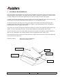
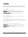
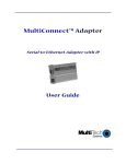
This set-up guide describes how to set up and operate the high-speed, thermal, point-of-sale (POS) printer
manufactured by Axiohm SARL. The printer has many features, which give advantages to retailers, and is
versatile enough to be used in other applications such as for printing out tickets and coupons.
Axiohm’s unique and patented paper-loading mechanism makes this printer the easiest-to-use POS printer
on the market. The fixed-head thermal printer engine gives a very high quality print.
An untrained operator can change the roll of paper quickly and reliably, minimizing downtimes and
avoiding paper jams. There are no messy ribbons to change, so good print quality can be ‘designed-in’
without operator skills or regular maintenance.
The printer uses Axiohm’s proprietary thick-film technology to achieve the longest-life print heads on the
market, as well as the longest-life cutter with the optional patented semi-rotating ceramic cutter.
As part of the total ‘easy-to-use’ philosophy, the printer uses a super-set of industry-standard software to
allow for easy installation. The existing software needs no modification and is ready to use.
The APOS printer will accurately print many barcodes, it allows custom characters to be downloaded and
it can execute macro functions.
Interfaces offered:
RS232 for greatest compatibility
Centronics parallel version.
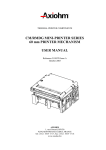
Opening cover
On / Off
Paper feed
Finger recess
to open cover
Paper exit
APOS 8 dots/mm Printer Series User Manual
Page 4 /39
Reference: FDE – 3107082 Issue Z
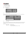
2
SPECIFICATIONS
2.1 Physical specification
2.1.1
2.1.2
Dimensions
Height
115mm
Width
170mm
Depth
205mm
Weight (with cutter)
1390 g
Print specification
The APOS printer uses a fixed-head thermal print head designed and manufactured by Axiohm, using
proprietary thick-film techniques to ensure the highest performance.
Print head type:
Printing width:
Number of dots across width:
Resolution (dot-density):
Character fonts
2.1.3
A
B
Thermal line
72 mm
576
8 dots / mm
12 x 24 (48 columns)
7 x 17 (64 columns)
Power supply
The printer requires a power supply of 24V at 2A minimum. Other voltages, which are required internally
for the micro controller and the communications ports, are generated internally from the 24V supply.
Specification:
Output voltage:
Output current:
24 VDC (no load)
2.0 A mean continuously
10 A peak during 4ms max (pulse cycle =30ms)
APOS 8 dots/mm Printer Series User Manual
Page 5 /39
Reference: FDE – 3107082 Issue Z
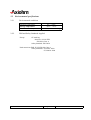
2.2 Environmental specifications
2.2.1
Environmental conditions
Operating temperature:
Storage temperature:
Maximum humidity:
2.2.2
0°C - +50°C
-40°C - +70°C
90% RH (non-condensing)
EMI and Safety Standards Applied
Europe
CE marking:
Directive: 89/336/EEC
EN55022 Class A
Safety Standard: EN 60950
North American EMI: FCC/ICES-003 Class A
Safety Standards: UL60950: 2000
cUL60950: 2000
APOS 8 dots/mm Printer Series User Manual
Page 6 /39
Reference: FDE – 3107082 Issue Z
2.3 Operational performance
2.3.1
Data hold up
A backup capacitor is fitted to the APOS printer to hold up RAM data for a minimum of 1.5 hrs after
losing external power. This means that all downloaded fonts, logos and bitmaps will be retained for the
data hold up period. However, the context of the printer is not saved, which means that the printer will
revert to its initial state when power is returned.
2.3.2
Paper specification
Paper width
Maximum paper roll diameter
(Maximum paper roll length)
Recommended papers
Emulsion (sensitive) side
80mm
80mm
82m (using 60gsm paper)
AXIOHM ref 3101123
KANZAKI F380
On outside of roll
* You must contact Axiohm if you wish to use an alternative type of paper; otherwise your warranty might
not be valid and you could cause damage to your printer.
2.3.3
Speed
The printer is capable of printing at a maximum speed of 60mm/s with 40% of the dots on (during 40% of
the time), provided that sufficient power supply current is available (See section 2.1.3 about power supply
requirements). The printer can achieve a speed of approximately 50mm/s when printing simple text using
the standard 2A power supply unit.
The actual speed can also be affected by the data rate at which information is sent to the printer over the
communication link. Sending large amounts of graphic data could reduce the actual speed.
2.3.4
Lifetime
The printer lifetime depends on the actual operating conditions and is defined by the MTBF of the
electronics and the wear characteristics of the electromechanical parts. The actual lifetime will therefore be
the minimum of the following three categories, depending on the particular application:
•
•
•
Electronic MTBF of 40,000 hrs of powered use
90km of paper used by the printer (with typically 15% of the dots heated)
One million cuts from the ceramic cutter mechanism.
APOS 8 dots/mm Printer Series User Manual
Page 7 /39
Reference: FDE – 3107082 Issue Z
2.4 Warranty
The printers or spare parts are guaranteed for a period of 6 (six) months, beginning at the delivery date (exworks).
The printers are guaranteed against defective material and/or workmanship. The warranty covers only, and
at AXIOHM’s choice, the cost of repair or replacement by AXIOHM in its factory, after restitution by the
customer of the printers or spare parts confirmed by AXIOHM to be defective (excluding assembling,
dismounting, shipping and other expenses).
The implementation of the warranty will not extend the warranty period.
Due to the complexity of the electronic and mechanical techniques used in the operation of such a printer,
AXIOHM does not warranty problems resulting from an installation not according to the published
specifications.
This warranty is subject to strict compliance with AXIOHM’s technical instructions for installation, use
and maintenance.
In particular, this warranty will not be valid for any defects due to:
Use of thermal paper other than those recommended by AXIOHM.
Incorrect maintenance.
Defective installation or modification not approved by AXIOHM.
Non-compliance, during any period, with the specified working conditions including the
electrical power supply specifications.
Abnormal wear or mechanical damage, including dot burning due to power overloads.
Transportation in packaging other than the type of carton / foam insert in which the printer
was originally packed.
Any transportation, storage or setting up which does not comply with the technical specifications given to
the customer by AXIOHM, or its official distributor, will invalidate this warranty.
In no event shall AXIOHM assume any liability in excess of that defined above. It is agreed that AXIOHM
will not be liable for any indemnity for accidents to persons, damage to property or for loss of earnings.
APOS 8 dots/mm Printer Series User Manual
Page 8 /39
Reference: FDE – 3107082 Issue Z
2.5 Order Codes
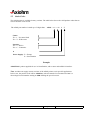
The APOS printer is available in many variants. The table below shows the valid product codes that are
used to describe each version.
The APOS part number is made up of 8 digits thus: APOS < x1> < x2> 0
E
Cutter
X1 = 1 : No cutter fitted
X1 = Y : With cutter
Interface
X2 = 2 : RS232
X2 = C : Centronics
0
Power Supply : E = Europe
G = Great Britain
Example
APOSY2OG: printer supplied for use in Great Britain, with a cutter and an RS232 interface.
Note: Axiohm can supply custom versions of the APOS printer to suit specific applications.
In this case, the product code will be APOSSxxx, where S stands for customized and xxx is a
chronological serial number starting at S000 defining the special version.
APOS 8 dots/mm Printer Series User Manual
Page 9 /39
Reference: FDE – 3107082 Issue Z
3
YOUR PRINTER
3.1 Getting ready to use the printer
3.1.1
Unpacking the printer
The printer comes in a plain cardboard carton with a reusable packing foam insert and separate pockets for:
One APOS printer
One set-up guide
One single 80m roll of thermal paper
One standard power supply with 24V power lead (optional)
One 1.8 m CEE22 power cable, with appropriate mains plug for the country of sale
The model number and serial number (including manufacturing week and batch number) of the printer will
be marked on the exterior of the packaging.
Make sure that no parts are missing or damaged. Report any deficiency to your supplier as soon as possible
after receiving the printer. The original packaging material should be kept to transport or return your
printer, if necessary.
3.1.2
Description of printer parts
The APOS printer contains a patented easy-loading printer mechanism designed and manufactured by
Axiohm. This mechanism consists of a main cavity into which a paper roll is dropped for loading. The
thermal print head is in front of this cavity and a rubber roller is attached to the lid of the mechanism.
When the lid is closed, the paper is trapped between the rubber roller and the print head to give close
alignment and consistent pressure.
3.1.3
Buttons
The APOS printer has two buttons on the front panel:
The ON/OFF button is physically connected to the hard reset on the main controller board. Even when it is
OFF, the printer is always powered.
The Paper Feed button’s normal function is to advance paper when the unit is not printing. The button
function may be disabled under software control and it can be used to control the action of a defined
macro. This button also activates a self-test printout (see section 2.7).
3.1.4
Indicator
A rectangular green LED is used to indicate the basic status of the printer. The LED is “off” when the
printer is off, and “on” under normal circumstances when the printer is on. It will flash when there is an
“error condition” such as when it is out of paper.
APOS 8 dots/mm Printer Series User Manual
Page 10 /39
Reference: FDE – 3107082 Issue Z
3.1.5
Cutter
The printer may be fitted with Axiohm’s patented semi-rotating ceramic cutter. It is split with one blade in
the lower cavity and the other fitted to the lid. These blades are also correctly aligned when the lid is closed
to make paper loading very easy and jam-free. Partial cuts or full cuts are possible under software control.
3.1.6
Connectors
The APOS printer can have up to 3 types of connectors:
Power connector: fitted to the base of the unit near the front. (See section 2.5.1 for detail)
Interface connector: fitted to the base of the unit closer to the rear; a 9-pin D-type in the case of serial
communication RS232, or a 25-pin D-type in the case of parallel communications (Centronics option).
(See section 2.5.2 for detail)
Drawer kick-out connectors (two): fitted at the rear of the printer. These appear as a pair of RJ11
connectors. (See section 2.5.3 for details)
3.1.7
Cable traps
Three clips are fitted into the base of the printer; they may be used to trap the power supply and interface
cables into recessed channels in the base.
3.1.8
Mounting holes
There are two holes in the base of the printer that allow the printer to be attached to a vertical surface such
as a wall or pillar. In this case, the printer should be mounted with the paper exiting from the top so that the
roll does not fall out when opening the cover.
3.1.9
Sensors
The APOS printer is fitted with three sensors, which detect abnormal conditions:
Door-closed sensor: a micro-switch sensor. To avoid damaging the print head, when the door is open,
printing is inhibited.
End-of-paper (EOP) sensor: detects the presence of paper near the print head. To avoid damaging the print
head, when no paper is detected, printing is inhibited.
Cutter sensor: used to detect if the cutter is in its home position before commencing a cut, and on
completion of a cut.
APOS 8 dots/mm Printer Series User Manual
Page 11 /39
Reference: FDE – 3107082 Issue Z
3.2 Choosing the proper location for your printer
The APOS printer may be installed in a variety of applications; but, to maintain optimum working
conditions from your unit, the following recommendations should be followed:
Avoid dirty or dusty locations, or those with excessive heat or humidity
Choose a stable level base or solid wall on which to mount the printer
Make sufficient space around the printer to ensure comfort while using your printer, including
sufficient access to open the lid while changing paper.
3.3 Loading paper
It is extremely easy to load a new paper roll into the printer by following these simple steps:
Open the cover and remove the old paper core;
Drop the new roll into the reservoir so that it will rotate in the correct direction (i.e. so that the
emulsion side of the paper rests against the print head)
Hold the front edge of the paper outside the main cavity at the front of the printer
Close the printer cover
3.4 Light indicator
When the light is on continuously, the printer is ready to operate.
When the light is flashing, this signals that an error has occurred.
3.5 Connectors & cables
To reduce the electromagnetic emissions and susceptibility, all cables should be screened. If you are not
using cables supplied by Axiohm for this purpose, please ensure that your cables match the printer and are
rated at the appropriate voltage and current capacities.
*Use of an inappropriate cable may seriously damage your printer!
3.5.1
Power connector
The connector is a shielded 6-pin female mini-Din plug.
6
5
4
3
2
Pins 1, 3 &5:
Pins 2, 4 & 6:
Shield:
GND
24V
EARTH
1
APOS 8 dots/mm Printer Series User Manual
Page 12 /39
Reference: FDE – 3107082 Issue Z
3.5.2
Communications interface connectors
RS232 interface uses 9-pin D-type male connectors
Centronics interface uses a 25-pin D-type female connector.
RS232 Connector
Cable for DTR/DSR protocol
CONNECTOR VIEW male DB9 connector
1
2
6
3
7
4
8
male DB9 connector
N/C 1:
RXD 2:
TXD 3:
DTR 4:
GND 5:
DSR 6:
RTS 7:
CTS 8:
N/C 9:
5
9
:1
:2
:3
:4
:5
:6
:7
:8
:9
N/C
RXD
TXD
DTR
GND
DSR
RTS
CTS
N/C
Note: RTS/CTS should be tied together if using DOS print commands on a PC station.
Centronics Connector
CONNECTOR VIEW
1
2
14 15
3
4
5
6
7
8
9 10 11 12 13
16 17 18 19 20 21 22 23 24 25
PINOUT
1
2
3
4
5
6
7
8
9
Strobe'
Data bit 0
Data bit 1
Data bit 2
Data bit 3
Data bit 4
Data bit 5
Data bit 6
Data bit 7
APOS 8 dots/mm Printer Series User Manual
10
11
12
13
14
15
16
17
Ack'
Busy
Paper Out'
Pulled to Vcc
n/c
Pulled to Vcc
Reset'
n/c
Page 13 /39
18
19
20
21
22
23
24
25
Gnd
Gnd
Gnd
Gnd
Gnd
Gnd
Gnd
Gnd
Reference: FDE – 3107082 Issue Z
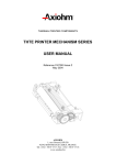
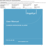
3.5.3
Drawer kick-out connector
The connector used to open a cash drawer and monitor, whether the drawer is opened or closed, is a 6-pin
modular RJ11 connector.
CONNECTOR VIEW
PINOUT
1 2 3 4 5 6
1:
2:
3:
4:
5:
6:
PRINTER
Frame ground
Solenoid 1 (-ve)
Switch (+ve)
Solenoid Common (+ve)
Solenoid 2 (-ve)
Switch (-ve)
CASH DRAWER
24V
(1A max)
4
S2
5
S1
2
S2
S1
Drawer-release
solenoids
5V
10k
3
Drawer open /
closed switch
SW
6
1
APOS 8 dots/mm Printer Series User Manual
Page 14 /39
Reference: FDE – 3107082 Issue Z
3.6 Configuration of the switches
Respect the following procedure in order to set the switches:
3.6.1
Switch the printer off
Set the switches as requested (see tables below)
Switch the printer on
RS232 mode
Switches 1,2,3 and 6 are used to define functions. Switches 4 and 5 are used to set the data transmission
speed (see Annex B1 for RS232 timing).
Switch
1
2
3
6
ON
XON/XOFF control
No Parity
Odd parity
(not used)
OFF
DTR/DSR
Parity
Even parity
(not used)
Switch numbers 4 and 5 are used to define the baud rate as follows:
Baud rate
4800
9600
19200
38400
3.6.2
Switch 4
OFF
ON
OFF
ON
Switch 5
OFF
OFF
ON
ON
Centronics mode
All switches should be set OFF for printers equipped with Centronics connectors.
3.7 Self test
A self-test is obtained by pressing the paper feed button during a reset (power up or pressing on/off
button). On entering the self-test mode, the printer checks its internal hardware and prints a report with the
following information:
product reference and software version
serial number
whether a cutter is fitted or not
what type of interface is fitted
switch settings (but not for Centronics versions)
address of printer (RS485 versions)
print density adjustment setting (set via software)
internal RAM status
APOS 8 dots/mm Printer Series User Manual
Page 15 /39
Reference: FDE – 3107082 Issue Z
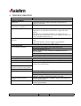
4
TROUBLE SHOOTING
Problem
a) Printer Problems:
Light is off.
Light is continuously on, but
printer does not operate.
Light is flashing.
Printer does not function when
turned on.
b) LED Problems:
Slow continuous flashing.
c) Printing Problems:
Printing quality is deteriorating
Colored stripe on the receipt.
Receipt does not come out all the
way.
Printer starts to print, but stops
while the receipt is being printed.
Receipt is not cut.
Print is light or spotty.
Vertical column of print is
missing.
One side of receipt is missing.
Possible Causes and What to Do
Check that the power-supply and cables connections are
properly connected.
Check to see if the interface cable is properly connected.
Check that the cover is closed properly.
Open the cover and make sure that there is paper left in the
printer.
Open the cover and check that there is no paper jam; if so,
unwind the paper until there are no more wrinkles and close the
cover with the wrinkled part out.
Check that the printer cables are properly connected on both
ends.
Check that the host or power supply is getting power.
Check that the receipt cover is fully closed.
You may be out of paper; put in a new paper roll.
Cover off; put the cover on.
Knife is unable to home; contact your authorized service
representative.
Print head is too hot; printing will resume when head cools.
Out of range voltages.
Print head may be getting dirty; see ”Cleaning your Printer”.
Paper is low; change the paper roll.
Paper is jammed; open the receipt cover, inspect the knife and
remove any jammed paper.
Check that the paper is loaded properly.
The print head is dirty; use recommended thermal receipt paper.
Variations in paper; increase print density in “Set Hardware
Options” of printer Configuration Menu as needed.
Serious printer electronics problem; contact your authorized
service representative.
Serious printer electronics problem; contact your authorized
service representative.
APOS 8 dots/mm Printer Series User Manual
Page 16 /39
Reference: FDE – 3107082 Issue Z
5
CLEANING YOUR PRINTER
The APOS printer is a highly reliable unit, which requires very little maintenance but may benefit from
cleaning as described in the next sections.
Before cleaning, unplug all electrical connections.
5.1 Cleaning the printer
Keep the external surfaces clean by wiping with a lightly damp cloth. Make sure that the inside surfaces
are kept dry at all times, and that the external surfaces are thoroughly dry before re-connecting.
5.2 Cleaning the print head
Depending of the environment in which the printer is used, the print head may accumulate dust. Therefore
it is necessary to clean it periodically in order to maintain a good print quality. The cleaning period
depends on the environment and the usage of the printer, but it should be cleaned at least once a year or up
to once a month in heavy-duty applications. The print head should always be cleaned immediately if the
print becomes visibly fainter due to contamination of the print head.
To clean the print head:
Switch the printer off.
Never clean the head immediately after printing, it may still be hot.
Open the cover of the printer and remove the roll of paper.
Clean the heating dots of the head with a cotton stick and a little alcohol solvent (ethanol,
methanol or IPA), but do not touch the print head with you fingers!
Allow the solvent to dry
Reload the paper and close the cover
APOS 8 dots/mm Printer Series User Manual
Page 17 /39
Reference: FDE – 3107082 Issue Z
6
PRINTER CONTROL SOFTWARE
Control codes are non-printable characters or sequences of characters, which affect the subsequent
operation of the printer. For your convenience, they are grouped below in logical sets of commands, which
can be used in the same context.
Throughout the following descriptions of the commands you will note that three special codes are used to
cause the printer to interpret the following byte or bytes as part of a command and not as printable
characters. These codes are:
Code
ESC
GS
AX
FS
Name
Escape
Graphic Sequence
Axiohm
KANJI sequence
Dec. value
27
29
31
28
Hex. value
1B
1D
1F
1C
General “escape sequence” commands
Often used for special graphic commands
Special commands for the APOS printer
General Kanji commands
The general command syntax is as follows:
Command
(Description)
(Format)
(Comments)
(Cross
reference)
Name and description of the command
The code sequence to be sent to the printer.
<nnh> is used to represent the hexadecimal number nn
<nn> is used to represent the decimal number nn
[ ] k is used when the sequence included in [ ] must be repeated k times
Additional information such as range allowed for the numbers or default values
Related commands
APOS 8 dots/mm Printer Series User Manual
Page 18 /39
Reference: FDE – 3107082 Issue Z
6.1 Commands
ESC =
(Description)
(Format)
(Comments)
Select device
<1Bh> <3Dh> <n>
It allows the user to select a printer.
If n = 0 all the printers are deselected.
If n = 1 to 32, the printer with address #n s selected, all the other printers are
deselected.
If n = 33 all the printers are selected.
The default value is n =1
(Cross reference) –
AX P
(Description)
(Format)
(Comments)
Adjust print density
<1Fh> <50h> <n>
This command allows the user to vary the print density by adjusting the
heating time between -32% and +10% of the nominal setting in 0.25% steps.
The percentage variation
∆% = (n - 128) / 4
0 <= n <= 168
(Cross reference) –
% is given by
ESC v
(Description)
(Format)
(Comments)
Send printer status byte
<1Bh> <76h>
The printer will transmit a single byte, which reflects the status of the printer
in accordance with the table below.
This command is ignored if the printer is fitted with a Centronics interface
because Centronics is not bi-directional.
(Cross reference) –
Bit
0
1
2
3
4
5
6
7
Function
(unused)
Door open
Paper
(unused)
(unused)
(unused)
(unused)
Cutter failure
APOS 8 dots/mm Printer Series User Manual
bit = 0
Close
Present
No
Page 19 /39
bit = 1
Open
Out
Yes
Reference: FDE – 3107082 Issue Z
AX V
Send printer software version
<1Dh> <56h>
The printer returns 4 characters representing the software version
eg. “01.0” for Version 1.0
(Cross reference) –
(Description)
(Format)
(Comments)
ESC @
(Description)
(Format)
(Comments)
(Cross reference)
Initialize printer
<1Bh> <40h>
Clears data in the buffer and initializes the printer settings.
–
ESC c5
Enable / disable paper feed switch
<1Bh> <63h> <35h> <n>
Paper feed disable if n is even
Paper feed enabled if n is odd
Default value is n = 0
(Cross reference) –
(Description)
(Format)
(Comments)
ESC R
(Description)
(Format)
(Comments)
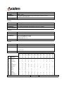
Select international character set
<1Bh> <4Ah> <n>
Modifies the set of printable characters in accordance with the table below.
0 <= n <= 10
(Cross reference) –
n
0
1
2
3
4
5
6
7
8
9
10
Country
U.S.A.
France
Germany
UK.
Denmark I
Sweden
Italy
Spain
Japan
Norway
Denmark II
23h
35
#
#
#
£
#
#
#
Pt
#
#
#
24h
36
$
$
$
$
$
¤
$
$
$
¤
$
Ascii Character Code
40h 5Bh 5Ch 5Dh 5Eh 60h 7Bh 7Ch 7Dh 7Eh
64
91
92
93
94
96 123 124 125 126
@
[
\
]
^
`
{
|
}
~
É
•
ç
§
^
`
é
ù
è
¨
É
Ä
Ö
Ü
^
`
ä
ö
ü
ß
@
[
\
]
^
`
{
|
}
~
@
Æ
Ø
Å
^
`
æ
ø
å
~
É
Ä
Ö
Å
Ü
é
ä
ö
å
ü
@
•
\
é
^
ù
à
ò
è
ì
@
¡
Ñ
¿
^
`
¨
ñ
}
~
@
[
¥
]
^
`
{
|
}
~
É
Æ
Ø
Å
Ü
é
æ
ø
å
ü
É
Æ
Ø
Å
Ü
é
æ
ø
å
ü
APOS 8 dots/mm Printer Series User Manual
Page 20 /39
Reference: FDE – 3107082 Issue Z
ESC D
(Description)
(Format)
(Comments)
Set tab positions
<1Bh> <44h> [<n>] k <00h>
n represents the nth character position at which you wish the tab to be set.
To set k tabs on a line, <n> must be sent k times ensuring that
n1<= n2... <= nk
The string of data must be terminated by the null character <00h>.
eg.:
The command <1Bh> <44h> <09h> <0Ch> <16h> <00h> will set 3 tabs such
that, by using the command HT one, two or three times, you will be able to
start printing on the 10th, 13th or 23rd column.
The default value for tab positions is every 8 characters.
Any change made to the width of the characters before setting the tabs will be
included in the tabs’ width; all the changes made after would be ignored.
(Cross reference) HT
ESC 3
Define line spacing
<1Bh> <33h> <n>
The character line spacing is set to a pitch of n/16 mm
0 <= n <= 255
The default is n = 68 which is equivalent to about 4.2mm pitch.
(Cross reference) ESC 2
(Description)
(Format)
(Comments)
ESC 2
(Description)
(Format)
(Comments)
(Cross reference)
Set to default line spacing
<1Bh> <32h>
The default line spacing is 68/16 mm (about 4.2mm)
ESC 3
ESC SP
Set spacing to right of characters
<1Bh> <20h> <n>
0 <= n <= 32, where n is specified in 1/8 mm units
Default value is n=0
If double-width mode is selected, the amount of space is doubled.
(Cross reference) –
(Description)
(Format)
(Comments)
APOS 8 dots/mm Printer Series User Manual
Page 21 /39
Reference: FDE – 3107082 Issue Z
ESC !
Set print mode
<1Bh> <21h> <n>
0 <= n <= 255
The value of n can be set to vary the mode of print according to the table
below.
Default value is n = 0 (ie. Font A in standard mode)
(Cross reference) –
(Description)
(Format)
(Comments)
Bit
0
1
2
3
4
5
6
7
Function
Character Font
(not used)
(not used)
Emphasized
Double height
Double width
(not used)
Underlined
Front
A
B
Bit = 0
A
Cancelled
Cancelled
Cancelled
Cancelled
Bit = 1
B
Set
Set
Set
Set
Front Selected
12 × 24
9 × 17
ESC –
Underline mode on / off
<1Bh> <2Dh> <n>
0 <= n <= 2
If n=0, underline is turned off
If n=1, underline mode of1 dot-line thickness is selected
If n=2, underline mode of 2 dot-line thickness is selected
(Cross reference) –
(Description)
(Format)
(Comments)
ESC E
Emphasized on / off
<1Bh> <45h> <n>
The emphasized mode is selected if n is odd.
The emphasized mode is cancelled if n is even.
(Cross reference) ESC ! (set print mode)
(Description)
(Format)
(Comments)
APOS 8 dots/mm Printer Series User Manual
Page 22 /39
Reference: FDE – 3107082 Issue Z
ESC G
Double-strike on / off
<1Bh> <47>
The double-strike mode is selected if n is odd.
The double-strike mode is cancelled if n is even.
(Cross reference) ESC ! (set print mode)
(Description)
(Format)
(Comments)
ESC {
(Description)
(Format)
(Comments)
Set / cancel upside-down character printing
<1Bh> <7Bh> <n>
This command rotates the text by 180° so that it prints correctly when the
printer is wall-mounted.
Upside-down character is enabled if n is odd
Upside-down character is disabled if n is even
0 <= n <= 255. Default value is n = 0
The command is valid only when it is used at the beginning of a line.
(Cross reference) –
ESC V
Set / cancel rotated characters
<1Bh> <56h> <n>
This command allows each character to be rotated by 90° clockwise.
0 <= n<= 1
n = 0 cancels rotated printing
n = 1 set rotating printing
(Cross reference) –
(Description)
(Format)
(Comments)
HT
(Description)
(Format)
(Comments)
(Cross reference)
Horizontal tab. moves the printing position to the next horizontal tab position
<09h>
Default tabs are every 8 characters
ESC D (set tabs)
APOS 8 dots/mm Printer Series User Manual
Page 23 /39
Reference: FDE – 3107082 Issue Z
ESC $
Set absolute position
<1Bh> <24h> <n1> <n2>
Sets the print starting position to the specified number of dots (1/8 mm units)
from the beginning of the line so that the position is (n1 + n2 x 256) dots from
the left hand side, where
0 <= n2 <= 1
If n2 = 0: 0 <= n1 <= 255
If n2 = 1: 0 <= n1 <= 192
ie: 0 <= (n1 + n2 x 256) <= 576
If the position exceeds the print area, the command is ignored.
(Cross reference) ESC ¥
(Description)
(Format)
(Comments)
ESC ¥
Set relative position
<1Bh> <5Ch> <n1> <n2>
Sets the print starting position to the specified number of dots (1/8 mm units)
from the current printing position, where
0 <= n2 <= 1
If n2 = 0: 0 <= n1 <= 255
If n2 = 1: 0 <= n1 <= 192
ie: 0 <= (n1 + n2 x 256) <= 576
If the position exceeds the print area, the command is ignored.
(Cross reference) ESC $
(Description)
(Format)
(Comments)
ESC a
Set left, center or right justification
<1Bh> <61h> <n>
Align the text to the specified position (left, center, right)
Align left if n=0 (default)
Align center if n=1
Align right if n=2
This command only works at the start of a new line.
(Cross reference) –
(Description)
(Format)
(Comments)
LF
(Description)
(Format)
(Comments)
(Cross reference)
Print contents of buffer and advance paper
<0Ah>
Moves the print position to the beginning of the next print line
ESC 2, ESC 3
APOS 8 dots/mm Printer Series User Manual
Page 24 /39
Reference: FDE – 3107082 Issue Z
ESC d
(Description)
(Format)
(Comments)
Print and line feed n character lines
<1Bh> <64h> <n>
This command prints the line in the buffer and performs n blank lines
including the line in the buffer.
0 <= n <= 255
(Cross reference) –
ESC J
(Description)
(Format)
(Comments)
Print and line feed n dot lines
<1Bh> <4Ah> <n>
The printer prints the data in buffer, feeds the paper by n/16 mm and moves
the print position to the beginning of the line.
0 <= n <= 255
(Cross reference) LF, ESC d, ESC 2, ESC 3
ESC i
(Description)
(Format)
(Comments)
(Cross reference)
Perform full cut
<1Bh> <69h> <n>
The command is valid only when a cutter is fitted.
ESC m
ESC m
(Description)
(Format)
(Comments)
(Cross reference)
Perform partial cut
<1Bh> <6Dh> <n>
The command is valid only when a cutter is fitted.
ESC i
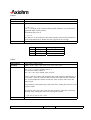
AX C
Select cut position
<1Fh> <43h> <n>
If n = 0, cut command will cut under last printed line.
If n = 1, cut command will cut over last printed line.
0 <= n <= 1
Default value is n = 1
(Cross reference) ESC i, ESC m
(Description)
(Format)
(Comments)
APOS 8 dots/mm Printer Series User Manual
Page 25 /39
Reference: FDE – 3107082 Issue Z
GS w
Set horizontal magnification of bar code
<1Dh> <77h> <n>
n defines how many 1/6mm units are used to print the thin line of each
barcode symbol. The thick lines will be set to twice the value of n.
2 <= n <= 4
Default value is n = 3
(Cross reference) GS h, GS k
(Description)
(Format)
(Comments)
GS h
Select vertical height of bar code
<1Dh> <68h> <n>
The vertical height will be set to n 1/8mm units.
1 <= n <= 255
Default value is n = 162
(Cross reference) GS k, GS w
(Description)
(Format)
(Comments)
GS k
Print bar code
<1Dh> <6Bh> <n> [<d>] k <00h>
n selects the bar code system to be used in accordance with the table below.
k is the number of <d> to be sent and will vary from one bar code symbol to
another.
(Cross reference) GS w, GS h
(Description)
(Format)
(Comments)
n
0
1
2
3
4
5
6
7
8
9
Bar code symbol
UPC-A
UPC-E
EAN13
EAN8
Code 39
Interleaved 2/5 (ITF)
Bar code
Code 128A
Code 128B
Code 128C
GS f
Select font for bar code data
<1Dh> <66h> <n>
If n = 0, font A is used.
If n = 1, font B is used.
0 <= n <= 1
(Cross reference) GS H
(Description)
(Format)
(Comments)
APOS 8 dots/mm Printer Series User Manual
Page 26 /39
Reference: FDE – 3107082 Issue Z
GS H
Select printing position of bar code data
<1Dh> <48h> <n>
The value of n is used to set how the characters will be printed in accordance
with the following table.
(Cross reference) GS f
(Description)
(Format)
(Comments)
n
0
1
2
3
Printing position
Not printed
Above bar code
Under bar code
Above and under bar code
ESC &
(Description)
(Format)
(Comments)
Define user-defined characters.
<1Bh> <26h> <s> <n> <m> [72] (m-n+1)
Each character is defined as an array of dots (bits) which is s-bytes high by abytes wide. The array contains bytes which represent the character ‘scanned’
from top to bottom and then from left to right. The first byte of the array (byte
p1) represents the top-left corner of the character with the most-significant bit
(MSB) at the top and the least-significant bit (LSB) seven dots below it.
Where any bit of the array contains a 1, a dot will be printed, where it contains
a 0, no dot will be printed. Thus s x a bytes are sent to define each character.
The newly defined characters will overwrite the existing Ascii characters
between characters 32 and 126 starting from character number n to character
number m. Therefore, the character array must be sent (m-n+1) times. If only
1 character is being sent, m should be set to the same value as n. The new
definitions will be retained, unless over-written by a new definition, until a
reset command is sent (ESC @) or until a bit image is defined (command GS
*).
1 <= s <=3 (ie. characters are 8, 16 or 24 bits high)
32 <= n <= m <= 126
Width of the font presently selected (see command AX f) <= a <= 12
The values <p1> to <ps x a> are all single-byte numbers
If the defined width of the new character, <a>, is less than the width of the
currently-selected font, then the new font will take the same width as the
current font and so will include blank spaces to its right. Therefore, this
command prohibits the definition of proportional fonts. In that case, you
should use the related command AX &
(Cross reference) ESC %, AX &
APOS 8 dots/mm Printer Series User Manual
Page 27 /39
Reference: FDE – 3107082 Issue Z
AX &
(Description)
(Format)
(Comments)
Define proportional characters
<1Fh> <26h> <s> <n> <m> [<a> <p1> <p2> ... <ps x a>] (m-n+1)
This command works as the ESC & command but allows the definition of
characters smaller than the selected font so that a proportional font may be
defined.
Each character is defined as an array of dots (bits) which is s-bytes high by abytes wide. The array contains bytes which represent the character ‘scanned’
from top to bottom and then from left to right. The first byte of the array (byte
p1) represents the top-left corner of the character with the most significant bit
(MSB) at the top and the least significant bit (LSB) seven dots below it.
Where any bit of the array contains a 1, a dot will be printed, where it contains
a 0, no dot will be printed. Thus s x a bytes are sent to define each character.
The newly defined characters will overwrite the existing Ascii characters
between characters 32 and 126 starting from character number n to character
number m. Therefore, the character array must be sent (m-n+1) times. If only
1 character is being sent, m should be set to the same value as n. The new
definitions will be retained, unless over-written by a new definition, until a
reset command is sent (ESC @) or until a bit image is defined (command GS
*).
1 <= s <=3 (ie. characters are 8, 16 or 24 bits high)
32 <= n <= m <= 126
0 <= a <= 16
The values <p1> to <ps x a> are all single-byte numbers
(Cross reference) –
ESC %
Enable / disable user-defined character set
<1Bh> <25h> <n>
If n is odd, the user-defined set is selected.
If n is even, the user defined set is cancelled (the internal set is used).
Default value is n = 0.
The user-defined character set and a downloaded bit image can not be defined
at the same time.
(Cross reference) ESC & (define character set)
(Description)
(Format)
(Comments)
APOS 8 dots/mm Printer Series User Manual
Page 28 /39
Reference: FDE – 3107082 Issue Z
GS *
(Description)
(Format)
(Comments)
Define down-loaded bit image
<1Dh> <2Ah> <n1> <n2> [<d>] k
The bit image is defined as an array whose width is 8 x n1 bytes and whose
height is n2 bytes.
As for the user-defined characters, the image data, [<d>], is defined with the
MSB at the top and with data sent to represent the image “scanned” from top
to bottom and then left to right. Therefore, there will need to be k bytes of data
sent to make up the entire image, where
k =(n1 + n2 x 8)
1 <= n1 <= 255
1 <= n2 <= 48
n1 x n2 <= 1311
Note that the maximum size image that can be printed is if n1 is 56; however,
for software compatibility with older printers the maximum value possible is
255. If the logical image is larger than what can be physically printed then
only part of the image will be printed, and the other data will be ignored.
The bit image will remain valid until ESC @ or ESC & or FS 2 is executed or
a new image is loaded.
(Cross reference) GS /
GS /
Print down-loaded bit image
<1Dh> <2Fh> <m>
The bit image defined by the command GS is printed in accordance with the
table below and depending on the value of the mode byte <m>.
0 <= m <= 3
(Cross reference) GS *
(Description)
(Format)
(Comments)
m
0
1
2
3
Mode
Normal
Double width
Double height
Double width and double height
APOS 8 dots/mm Printer Series User Manual
Page 29 /39
Reference: FDE – 3107082 Issue Z
ESC *
(Description)
(Format)
(Comments)
Print bit image
<1Bh> <2Ah> <m> <n1> <n2> [<d>] (k x n)
The mode of printing the bit image is defined by the value of m as given in the
table below.
m = 0, 1, 32 or 33
Beware that if an invalid value of m is sent, the command will be ignored and
the following bytes may be interpreted as either printable or control
characters.
The bit image itself is defined as an array whose height is n bytes where
for m = 0 or 1: n = 1
for m = 32 or 33: n = 3
The width is defined by the double-byte number <n1> <n2>. In normal
density, 1 bit represents a width of 2 dots but in double density, 1 bit
represents a width of 1 dot so the width of the data array is therefore k bytes
where
k =(n1 + n2 x 256)
When m = 0 or 32: 0 <= k <= 288
When m = 1 or 33: 0 <= k <= 576
As for the user-defined characters, the image data, [d], is defined with the
MSB at the top and with data sent to represent the image “scanned” from top
to bottom and then left to right. Therefore, there will need to be (k x n) bytes
of data sent to make up the entire image. If k exceeds the values given above,
subsequent data transfers will be ignored.
(Cross reference) –
m
Mode
0
1
32
33
8 dot single density
8 dot double density
24 dot double density
24 dot double density
APOS 8 dots/mm Printer Series User Manual
Vertical direction
#
Density
Dots
8
2 dots/mm
8
2 dots/mm
24
6 dots/mm
24
6 dots/mm
Page 30 /39
Horizontal direction
# Dots
Density
Max
288
3 dots/mm
576
6 dots/mm
288
3 dots/mm
576
6 dots/mm
Reference: FDE – 3107082 Issue Z
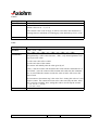
ESC p
(Description)
(Format)
(Comments)
Generate solenoid pulse
<1Bh> <70h> <m> <n1> <n2>
Generates a pulse on pin m of the drawer kick-out connector in accordance
with the table below.
n1 x 2 ms is the on-time of the pulse.
n2 x 2 ms is the off-time of the pulse.
0<= n1 <= n2 <= 255
(Cross reference) –
m
0
1
2
3
Connector
1
1
2
2
Pin
2
5
2
5
ESC u
(Description)
(Format)
(Comments)
Transmit cash drawer status
<1Bh> <75h> <n>
To request status of drawer 1, set n=0
To request status of drawer 2, set n=1
0 <= n <= 1
The printer returns a single byte. If the return byte is o (zero) the drawer is
closed. If the return byte is non-zero, the drawer is opened.
This command is ignored if the printer is fitted with a Centronics interface
because Centronics is not bi-directional.
(Cross reference) –
APOS 8 dots/mm Printer Series User Manual
Page 31 /39
Reference: FDE – 3107082 Issue Z
GS C0
(Description)
(Format)
(Comments)
Select counter print mode
<1Dh> <43h> <30h> <m> <n>
Sets the format of how the counter is printed.
0 <= m <= 5
If m = 0, all digits of the counter will be printed, otherwise <m> of the leastsignificant digits will be printed.
The default value is m=0
0 <= n <= 2
The value of <n> describes how the printed counter value will be justified as
shown in the table below. Both m and n are ignored if out of range.
(Cross reference) GS c, GS C, GS C1, GS C2
n
0
1
2
Adjustment
right
right
left
Empty digits filled
with spaces
with 0s
with spaces
GS C1
(Description)
(Format)
(Comments)
Select binary counter mode
<1Dh> <43h> <31h> <n1> <n2> <n3> <n4> <n5> <n6>
The start value of the counter is
start = (n1 + n2 x 256), default value is 1
The end value of the counter is
end = (n3 + n4 x 256), default value is 65535
If start > end, the counter will increment after each time the command GS c is
used. If end > start, the counter will decrement after each time the command
GS c is used. When the counter exceeds the value of end it will reset to the
value of start.
The increment or decrement step is the value of n5. Setting this value to 0 will
stop the counter.
The counter will reset to the value start only n6 times. After this, it will stop
counting. Also, setting this value to 0 will stop the counter.
0 <= n1, n2, n3, n4, n5, n6 <=255
(Cross reference) GS C0, GS C2, GS c, GS C
APOS 8 dots/mm Printer Series User Manual
Page 32 /39
Reference: FDE – 3107082 Issue Z
GS C2
(Description)
(Format)
(Comments)
Set binary counter value
<1Dh> <43h> <32h> <n1> <n2>
Counter value = n1 + n2 x 256
Default values are n1 = 1, n2 = 0
If the counter value is out of range, it will be converted to the maximum (if
counting-down) or minimum (if counting-up) value defined by GS C1 or GS
C.
(Cross reference) GS C0, GS C1, GS C, GS c
GS C
(Description)
(Format)
(Comments)
Select decimal count mode
<1Dh> <43h> <3Bh>
<n1> <3Bh> <n2> <3Bh> <n3> <3Bh> <n4> <3Bh> <n5> <3Bh>
With this counter, all parameters are entered as binary-coded decimal digits
and separated by a semi-colon character, <3Bh>. Any omitted parameter will
keep its previous value.
n1 is the start value of the counter
n2 is the end value of the counter
The counter will initially take the value given by n5
If start > end, the counter will increment after each time the command GS c is
used. If end > start, the counter will decrement after each time the command
GS c is used. When the counter exceeds the value of end it will reset to the
value of start.
The increment or decrement step is the value of n3. Setting this value to 0 will
stop the counter. The counter will reset to the value start only n4 times. After
this, it will stop counting. Also, setting this value to 0 will stop the counter.
0 <= n1, n2, n5 <= 65535
0 <= n3, n4 <=255
(Cross reference) GS C0, GS C1, GS C2, GS c
APOS 8 dots/mm Printer Series User Manual
Page 33 /39
Reference: FDE – 3107082 Issue Z
GS c
Print counter value
<1Dh> <63h>
Puts the current value of the counter in the print buffer & updates the counter.
(Description)
(Format)
(Comments)
The format of the printed value is set by the GS C0 command.
(Cross reference) GS C, GS C0, GD C1, GS C2
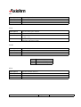
GS :
Set start / end of macro definition
<1Dh> <34h>
The macro definition starts and ends with this command. The length of the
macro must not exceed 2048 bytes.
(Cross reference) GS ^
(Description)
(Format)
(Comments)
GS ^
Execute macro
<1Dh> <5Eh> <n1> <n2> <n3>
The macro defined between the GS: commands will be executed n1 times.
(Description)
(Format)
(Comments)
t is the time to wait before executing the macro where the time t is given by
t = n2 x 100 ms
n3 specifies the way to execute the macro in accordance with the table below.
(Cross reference) GS :
n3
0
1
Executing mode
Continuous mode:
The macro is executed n1 times with interval t between each
execution.
Paper feed button mode:
After waiting t, the led blinks and the printer waits for the paper
feed button to be pushed to execute the macro. This operation is
repeated n1 times.
APOS 8 dots/mm Printer Series User Manual
Page 34 /39
Reference: FDE – 3107082 Issue Z
FS !
(Description)
(Format)
(Comments)
Specifies Kanji print mode
<1Ch> <21h> <n>
0 <= n <= 255
The value of n can be set to vary the mode of print according to the table
below.
Default value is n = 0
Bit
0
1
2
3
4
5
6
7
Function
(not used)
(not used)
Double height
Double width
(not used)
(not used)
(not used)
Underlined
Bit = 0
Cancelled
Cancelled
Cancelled
Bit = 1
Set
Set
Set
FS &
(Description)
(Format)
(Comments)
Specifies Kanji mode
<1Ch> <26h>
Valid if self test detects the special added Kanji board which means :
KANJI SET = ON
(Cross reference)
FS Specifies Kanji underlined mode
(Description)
<1Ch> <2Dh> <n>
(Format)
0<= n<= 2
(Comments)
(Cross reference)
n
0
1
2
Function
cancels underlined Kanji
1 dot underlined Kanji
2 dots underlined Kanji
APOS 8 dots/mm Printer Series User Manual
Page 35 /39
Reference: FDE – 3107082 Issue Z
FS .
Cancels Kanji mode
(Description)
<1Ch> <2Eh>
(Format)
(Comments)
(Cross reference)
FS S
Specifies Kanji space amount
<1Ch> <53h> <n1> <n2>
0<= n1 <= 32
0<= n2 <= 32
(Cross reference) n1 defines left space in dots
n2 defines right space in dots
(Description)
(Format)
(Comments)
FS W
Specifies Kanji 4 fold mode
(Description)
<1Ch> <57h> <n>
(Format)
0<= n<= 255
(Comments)
(Cross reference)
n
0
1
Function
cancels 4 fold Kanji
specifies 4 fold Kanji
FS 2
Specifies external character
(Description)
<1Ch> <32h> <a1> <a2> <Dn>
(Format)
(see next page)
(Comments)
(Cross reference)
APOS 8 dots/mm Printer Series User Manual
Page 36 /39
Reference: FDE – 3107082 Issue Z
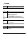
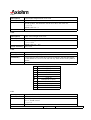
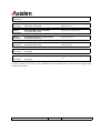
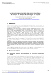
Defining the external characters FS + ‘2’ + a1 + a2 +Dn
Kanji characters are downloaded one by one
Code: 1Ch + 32h + a1 + a2 + Dn
a1 = 77h or 78h
a2 = 21h to 7Eh (meaning 94 characters)
Dn = p1, p2, p3 ... p72 (= 72 data kanji 24 × 24)
A1
77h
78h
Modify font user (see code ESC &)
Font user A
Font user B
24 dots
MSB
P1
24 dots
LSB
P2
P 72
P3
If images are loaded, they use downloading fonts (see page 31 ESC &)
If a problem occurs in downloading mode (for row or column code), printer indicates
! + 36 data in Kanji mode, and !* + 72 data in ascii mode.
APOS 8 dots/mm Printer Series User Manual
Page 37 /39
Reference: FDE – 3107082 Issue Z
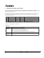
7
SPARES
All spare parts kits are supplied as individually packaged loose parts. It is possible to obtain different
groups of spare parts kits. AXIHOM customer service will provide the list later.
Reference
Designation
Contents
3101046
DOOR OPEN SWITCH KIT
Door switch (x1)
For Products:
APOSY20E, APOSY20G
3101047
KNIFE SWITCH KIT
For Products:
APOSY20E, APOSY20G
3101051
PAPER GUIDE KNIFE KIT
For Products:
APOSY20E, APOSY20G
3101052
PRINT HEAD SPRING KIT
For Products:
APOSY20E, APOSY20G
3101053
COVER SPRING KIT
For Products:
APOSY20E, APOSY20G
3102263
PAPER FEED MOTOR KIT
For Products:
APOSY20E, APOSY20G
3102264
COVER OPEN SWITCH KIT XPGE/APOSS
For Products:
APOSY20E, APOSY20G
3102265
PAPER OUT KIT APOSS
For Products:
APOSY20E, APOSY20G
3102268
CABINET BASE KIT CHARCOAL APOSS
For Products:
APOSY20E, APOSY20G
Charcoal bottom frame (x1)
Anti-slip pad (x4)
Cable clip (x3)
3102269
GROUND KIT XPGE/APOSS
Ground flex (x1)
For Products:
APOSY20E, APOSY20G
3103100
POWER SUPPLY KIT GB APOS
For Products:
APOSY20G
3103101
POWER SUPPLY KIT FR APOS
For Products:
APOSY20E
APOS 8 dots/mm Printer Series User Manual
Micro switch without lever (x1)
Upper paper guide (x1)
Print head spring (x1)
Cover spring (x1)
Stepper motor (x1)
Cover switch (x1)
Equipped opto sensor support (x1)
GB power supply (x1)
European power supply assembly (x1)
Page 38 /39
Reference: FDE – 3107082 Issue Z
PRINT HEAD KIT 8 DOTS/MM ~ to be created
8 dots/mm print head (x1)
3103212
EQUIPPED PLATEN KIT ~ to be created
For Products:
APOSY20E, APOSY20G
platen (x1)
Platen gear (x1)
3104129
TOP ASSEMBLY KIT APOSS001
Light gray top assembly (x1)
For Products:
APOSY20E, APOSY20G
3105803
PAPER FEED BIPOLAR MOTOR KIT
For Products:
APOSY20E, APOSY20G
3107094
FITTED PLATEN KIT APOSXCKJ
For Products:
APOSY20E, APOSY20G
PSUI5000
50W POWER SUPPLY KIT W/O CABLE APOS 50W power supply (x1)
For Products:
APOSY20G
PSUI500E
50W POWER SUPPLY KIT W/CABLE APOS
For Products:
APOSY20E
3103211
For Products:
Bipolar motor (x1)
Molded platen (x1)
Platen gear (x1)
European 50W power supply assembly
(x1)
* Screws, washers, rivets and any other small hardware not mentioned in the contents list are supplied with
the kits when needed.
APOS 8 dots/mm Printer Series User Manual
Page 39 /39
Reference: FDE – 3107082 Issue Z