1
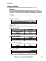
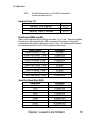
AGM Electronics, Inc – Dial-Up / Leased-Line Modem, Series ( ) 5019-1
Manual Rev A
User Manual
CD
+
-
CTS
RTS
DTR
DSR
.
RI
RX
TX
PHONE
LINE
DLM
Dial-Up / Leased-Line Modem
Dial-Up / Leased-Line Modem
CONTENTS
INTRODUCTION ........................................................................................................................................................... 1
Overview.................................................................................................................................................................. 2
Theory of Operation and Construction .............................................................................................................. 2
General Specifications .......................................................................................................................................... 4
HARDWARE INSTALLATION..................................................................................................................................... 5
TELEPHONE CONNECTION ................................................................................................................................... 5
LEASED-LINE CONNECTION ................................................................................................................................. 5
POWER CONNECTION ............................................................................................................................................ 5
CONNECTING TO A PERSONAL COMPUTER..................................................................................................... 6
CONNECTING TO AGM DATA HANDLER (DH) RS232....................................................................................... 7
CONNECTING TO AGM INTEGRATED CONTROL STATION (ICS) .................................................................. 7
CONNECTING TO AGM UNIVERSAL WEB STATION (UWS) ............................................................................ 8
CONNECTING TO A 3RD PARTY PLC..................................................................................................................... 8
GETTING STARTED .................................................................................................................................................... 9
SETTING DLM FOR DIAL-UP OPERATION........................................................................................................... 9
SETTING DLM FOR LEASED-LINE OPERATION............................................................................................... 11
CONFIGURATION ...................................................................................................................................................... 13
ENTERING COMMAND MODE.............................................................................................................................. 13
COMMON COMMANDS.......................................................................................................................................... 14
Answer (A)............................................................................................................................................................. 14
Dial (D).................................................................................................................................................................... 14
Echo Character (E)............................................................................................................................................... 14
Hang Up (H0)......................................................................................................................................................... 14
Monitor Speaker (M) ............................................................................................................................................ 14
Result Codes Enable (Q)..................................................................................................................................... 14
Result Codes Format (V)..................................................................................................................................... 14
Carrier Detect (&C)............................................................................................................................................... 14
Data Terminal Ready DTR Control (&D) ........................................................................................................... 15
Load Factory Settings (&F0) .............................................................................................................................. 15
Flow Control (&K)................................................................................................................................................. 15
Leased-Line (&L) .................................................................................................................................................. 15
NOTE:
For Leased-Line operation one DLM must be set for Originate and the other must be set for
Answer. 15
DSR Control (&S) ................................................................................................................................................. 15
Display Configuration Settings (&V)................................................................................................................. 15
Save Changes (&W0)........................................................................................................................................... 15
AT Command Control (%DC)............................................................................................................................. 15
Inactivity Timer (\T) .............................................................................................................................................. 16
Data Format ($EB) and (#P)................................................................................................................................ 16
Serial Port Baud Rate ($SB) ............................................................................................................................... 16
MODULATION COMMANDS.................................................................................................................................. 17
Modulation Selection (+MS=) ............................................................................................................................. 17
Display Modulation Selection (+MS?)............................................................................................................... 17
Error Control (&Q)................................................................................................................................................ 17
S REGISTERS.......................................................................................................................................................... 18
Dialup / Leased Line Modem
TECHNICAL SUPPORT .............................................................................................................................................19
DIAGNOSTICS AND TROUBLE SHOOTING ..........................................................................................................20
INDICATOR LIGHTS................................................................................................................................................20
TROUBLESHOOTING HINTS.................................................................................................................................20
Loss of Connection / Failure to Connect..........................................................................................................20
Failure to Disconnect on Dial-Up Connections...............................................................................................23
Failure to Disconnect on Loss of Carrier .........................................................................................................24
DLM Tries to Connect Immediately on a Dial-Up Phone Line.......................................................................24
APPENDIX A................................................................................................................................................................25
WIRING AND SIMPLIFIED DIAGRAM...................................................................................................................25
Dialup / Leased Line Modem
Introduction
Introduction
Thank you for purchasing the AGM Dial-Up / Leased-Line Modem (DLM). The AGM Dial-Up /
Leased-Line Modem provide a variety of cost effective data communication possibilities. This
manual covers installation and setup of the more commonly used configurations.
Screw Terminal Connections
Pin
1
2
Description
Power (+)
Power (-)
Carrier Detect Indicator
CTS Indicator
RTS Indicator
DTR Indicator
RS232 Connector (Female)
DSR Indicator
Ring Indicator
Monitoring Speaker
Phone Line Connection
(RJ11)
1
Dialup / Leased Line Modem
Introduction
Overview
The AGM AUX/DIN 5019-1 DLM is a low cost V.92 modem which supports Leased-Line as
well as Dial-Up connections. The DLM complies with FCC and other international regulations
for connection to public telephone systems. The DLM may also be used over a dry metallic
pair of lines.
The DLM is for use with RS232 system.
The standard DLM communicates using the V.92 modem standard and is backwards
compatible with earlier modem standards. It is configured using the AT command set
common with most commercial Dial-Up modems found in desktop and laptop computers.
The default configuration of the DLM will automatically detect the correct data
communications rate however the DLM can be set to use a specific rate such as 9600 bps if
required. Fixing the communications data rate can eliminate some connection problems
when communication conditions are not optimal.
Theory of Operation and Construction
The heart of the DLM is an industrial hardened V.92 modem that integrates most of the
common error correcting and data compression algorithms found in many commercial
modems such as those found in your desktop or laptop computer. Unlike the modem found
in your desktop, the DLM also incorporates a Leased-Line feature which allows the DLM to
be used over a Leased-Line from the phone company or via a dry metallic pair of wires.
The DLM may be used with any protocol that uses 7 or 8 bit asynchronous data. This
includes but is not limited to: ASCII Modbus, RTU Modbus, DF1, or DNP3. You do not need
to own AGM Electronics Inc. equipment to use the DLM.
The DLM is configured by using a computer and any terminal emulation software such as
AGM’s SCADA, AGM’s Communicator or Hyper Terminal which is packaged with Microsoft
Windows. The DLM may be configured in the field using a laptop computer and RS232
cable.
When used for a Dial-Up connection the DLM acts like any external Dial-Up modem that you
may have connected to your computer. When the DLM receives a dial command “EG
ATD123-4567” the DLM will go off hook, check for a dial tone and then dial the number.
When the receiving DLM or modem detects a ring on the phone line, the modem answers
then emits a tone. When the originating DLM detects the tone from the answering modem
the two modems will then attempt to negotiate a connection rate. Once the data rate has
been negotiated the CD light will be turned on and if enabled a connect message will be sent
to each of the connected devices.
When used in the Dial-Up configuration the DLM is compatible with most other commercial
modems that adhere to one of the supported standards.
Dialup / Leased Line Modem
2
Introduction
When used with a Leased-Line connection one DLM must be set up to “originate” and the
other to “answer”. After approximately 30 seconds after power up one DLM will start emitting
a tone and the other DLM will listen for the tone. Once the tone is detected the two DLM’s will
negotiate a connection as in a Dial-Up connection.
NOTE:
In Leased-Line mode the AGM Electronics DLM is only compatible with another
AGM Electronics DLM. Connection to other Leased-Line modems is not
supported. Also, multi-drop connections are not supported.
When you order your DLM indicate how you would like to have the DLM configured. AGM
Electronics Inc. will configure your DLM at the factory free of charge.
The hermetically sealed assembly minimizes installation costs.
3
Dialup / Leased Line Modem
Introduction
General Specifications
Connections – 1 RS232C; Power; RJ-11 Telephone Company
Baud Rate – 0 – 300; 1200; 2400; 4800; 7200; 9600, 12,000; 14,400; 19,200; 21,600;
24,000; 26,400; 28,800; 31,200; 33,600 bps
Data Compatibility – V.92; V.34 enhanced; V.34; V.32bis; V.32; V.22bis; V.22; Bell 212A and
103/113; V.21 and V.23
Data Compression – ITU-T V.44; V.42.bis; MNP 5
Error Correction – V.42
Status Indicators – 8
Operating Temperature Range, -20/80 deg C
Adjustments – Operator configurable locally from a PC
Power – 11/30 VDC +/- 10%, nominal 2.5 Watts
Physical – 3 X 1.4 X 3.5 (DIN), 3 X 1.4 X 2.7 (AUX)
Safety Certifications – UL60950; cUL60950; EN60950; IEC6090; ACA TS001 / AS 3260
EMC Certifications – FCC Part 15; Canadian EMC; EN 55022; EN 55024; GB4943; GB9254
Registration No – AU7USA-25814-M5-E
Ringer Equivalence – 0.3B
Dialup / Leased Line Modem
4
Hardware Installation
Hardware Installation
The DLM is available pre-configured to your application. When pre-configured, the DLM is
ready for use and you only need to connect your equipment. If not pre-configured or if you
need to modify the configuration you will need to connect the DLM to a computer containing a
RS232 serial port and terminal emulation program. Hyper Terminal is available on any
Microsoft Windows 95/98/NT/2000/XP system.
Telephone Connection
The telephone line connector on the DLM is a standard RJ-11 telephone jack. Use a
standard telephone modular cable to connect between the DLM and the RJ-11 telephone
jack supplied by the telephone company.
NOTE:
The DLM should only be plugged into a standard telephone line or dry metallic pair
of lines. Some digital telephone and other systems may also use a RJ-11 jack for
connecting their digital phones. The DLM is not compatible with these types of
systems and plugging the DLM into one of these systems may result in damage to
the DLM and phone system.
Leased-Line Connection
The DLM uses the same RJ-11 jack for connecting Leased-Lines as well as standard Dial-Up
lines. The DLM will operate with a dry metallic pair of lines. Connect the dry pair to a
modular RJ-11 plug or jack then plug the dry pair into the DLM’s RJ-11 jack. Use the two
center connections of the RJ-11. The phone lines used by the DLM are not polarized.
Power Connection
The DLM will operate from either a 12 VDC or 24 VDC supply system that is capable of
supplying 300 mA. Connect the positive lead of your power supply to pin 1 of the connector
and the negative lead to pin 2 of the connector. Should you ever be required to remove the
DLM you may un-plug the connector by lifting straight up from the body of the DLM. You do
not need to remove the power wires once installed.
When power is applied the “DSR” light should turn on immediately followed by the “CTS” no
more than one second later. Until you connect up your computer, PLC or other RS232
device these are the only two lights that will be on.
5
Dialup / Leased Line Modem
Hardware Installation
Connecting to a Personal Computer
Use the following procedure to connect the DLM to your computer for either configuration
changes or use.
You will need a “straight-through” cable to connect to the DLM. This cable should have a 9 or
25 pin female connector on one end to match the connector on you computer and a 9 pin
male connector on the other end to mate with the DLM. Cables, adapters and gender
changers designed for connecting a computer to a modem are available through many
computer, electronic or office supply stores.
The DLM also supports RS232 using only 3 wires, Transmit, Receive and Ground. Typically
3 wire RS232 is only used with custom cables to reduce the wiring cost. If using 3 wire
RS232 you will need to disable DTR detection and hardware handshaking by configuring the
DLM with “AT&K0&D0&W0” command. These changes are done via configuration
commands entered while connected to the DLM. You may need to initially connect to the
DLM using a standard RS232 cable or order your DLM preconfigured for 3 wire operation.
NOTE:
While using the DLM with only 3 RS232 wires the “RTS” and “DTR” lights will
remain off. You will also not be able to use hardware handshaking or be able
to hang up the phone line by toggling the “DTR” line. Make sure any
connected hardware does not require the use of these lines.
1. Plug one end of the RS232 cable into an available RS232 communications port your
PC. This port is normally a 9 pin male D connector; however it may also be a 25 pin D
connector in some cases. Consult with your PC documentation for the location of this
connector.
2. Plug the other end of the RS232 cable from your PC into the 9 pin female D
connectors on the top of the DLM.
3. Start Hyper Terminal or other terminal emulator program. Select direct connect to the
serial port connected to the DLM. Unless configured for another baud rate or data
format, select 9600 bps (baud), 8 data bits, no parity, and 1 stop bit. If connecting for
configuration, turn off all handshaking.
If properly connected and not using a 3 wire connection the “CTS”, “RTS”, “DTR” and
“DSR” lights should be on. If not on check your cable connections and RS232 port on
your computer. If using 3 wire RS232 the “RTS” or “DTR” lights will be off. You can
only test a 3 wire RS232 connection by observing the “TX” light on the DLM and typing
keys on your keyboard while connected to the DLM.
4. Cycle the power and wait for the “CTS” and “DSR” lights to turn on. Then within 10
seconds type “ATi” followed by a carriage return (Enter key) in your terminal emulator
program. If properly connected you should see a text response on your screen. The
“TX” light should flash when you are typing. The “RX” light may flash when you type a
key or just after you press the carriage return key (Enter key).
Dialup / Leased Line Modem
6
Hardware Installation
NOTE:
In some cases you can simply check the connection by entering just the
“AT” command and watching for “AT” to be echoed followed by “OK”. The
echoing of command characters as well as the response codes can be
disabled so simply entering “AT” will not work. Also when used in the
Leased-Line mode the DLM will only accept commands within the first 10
seconds after power up. Following the above procedure of cycling the
power then entering “ATi” will work in all cases.
Connecting to AGM Data Handler (DH) RS232
To connect a DLM to a RS232 Data Handler you will need a 9 pin female to 9 pin male nullmodem cable.
1. Plug one end of the RS232 cable into the 9 pin male connector on the Data Handler.
2. Plug the other end of the RS232 cable into the 9 pin female D connector on top of the
DLM.
3. Power up both the Data Handler and DLM. If properly connected the “DTR”, “DSR”,
“CTS” and “RTS” lights should be on. If “RTS” light is off the Data Handler may be
configured for half-duplex operation you may either turn off the half-duplex in the Data
Handler or disable the hardware handshaking in the DLM. Hardware handshaking
may be disabled by connecting the DLM to a computer then entering “AT&K0&W0”.
Connecting to AGM Integrated Control Station (ICS)
To connect a DLM to an ICS you will need a 9 pin male to 25 pin female straight through
cable.
1. Plug the 25 pin end of the cable of the RS232 cable into the 25 pin D connector on the
back of the ICS.
2. Plug the other end of the RS232 cable into the 9 pin female D connector on top of the
DLM.
3. Power up both the ICS and DLM. If properly configured the “DTR”, “DSR”, “CTS”, and
“RTS” lights should be on. If these lights are not on check your cable connections.
7
Dialup / Leased Line Modem
Hardware Installation
Connecting to AGM Universal Web Station (UWS)
To connect a DLM to a UWS Data Handler you will need a 9 pin female to 9 pin male straight
through cable.
1. Plug one end of the RS232 cable into one of the 9 pin male connectors on the UWS.
Select either “A” or “B” depending on which port will be used with the DLM.
2. Plug the other end of the RS232 cable into the 9 pin female D connector on top of the
DLM.
3. Power up both the UWS and DLM. If properly configured the “DTR”, “DSR”, “CTS”,
and “RTS” lights should be on. If these lights are not on check your cable
connections.
Connecting to a 3rd Party PLC
The DLM supports any PLC that uses a protocol based on 7 or 8 data bit asynchronous serial
communications. This includes ASCII Modbus, RTU Modbus, Allen-Bradley DF1 Half Duplex
and DNP3 protocols. You must have the appropriate RS232 interface installed. Consult with
your PLC manufacture on the RS232 interface to use.
You will need a cable to connect from your PLC to a Modem. If a cable of this type is not
available you will need a Null-Modem adapter and possibly a gender changer to connect your
PLC to the DLM. Null-Modem adapters and gender changers are typically available through
many computer, electronic or office supply stores.
1. Plug one end of the RS232 cable into your PLC. See your PLC documentation for
making this connection.
2. Plug the other end of the RS232 cable from the PLC into the 9 pin female D connector
on the top of the DLM.
3. Power up both the DLM and PLC. If properly configured the “DTR”, “DSR”, “CTS”,
and “RTS” lights should be on.
Some PLC’s may not provide full hardware handshaking. These PLC’s may still be
used with the DLM however you will need to disable the hardware handshaking and
DTR control in the DLM. Hardware handshaking may be disabled by connecting the
DLM to a computer then entering “AT&K0&W0”. DTR control may be disabled by
connecting to a computer and entering “AT&D0&W0”.
Dialup / Leased Line Modem
8
Getting Started
Getting Started
The DLM may be preconfigured at the factory. In this case your DLM should be ready to use
after you have made all hardware connections. If not preconfigured the following two
sections will provide instruction on configuring your DLM. See the Configuration Commands
section for details on some of the available DLM configuration commands.
To configure your DLM you will need to connect to a computer running Hyper Terminal or
other terminal emulator program. See Connecting to Personal Computer section above for
details on how to connect to your computer.
Setting DLM for Dial-Up Operation
The basic configuration for Dial-Up operation is the same whether the DLM will be dialing out
or answering. Each of the following commands will be entered then followed with a carriage
return (Enter Key). After entering each command wait for the “OK” response.
1. Turn on the DLM and as soon as the “DSR” and “CTS” lights turn on enter:
AT%DC0
NOTE 1: You may not get a response from this command. Some configurations
disable the response to commands as well as the echoing of characters.
NOTE 2: It is possible to set up the DLM to ignore any commands. To break out of
this mode the “%DC0” command must be sent within the first 10 seconds
after power up.
2. Reset the DLM to its factory defaults by entering: AT&F0
NOTE 1: You will get an “OK” response from this command.
NOTE 2: We recommend always restoring the DLM to factory defaults and
reentering all settings in this procedure. This guarantees the DLM is in a
known condition.
3. For connections other than to a computer where the data rate (Baud Rate) and data
format can be determined from the “AT” command the DLM will need to be set to the
correct data rate and data format. Depending on the data rate of your connection
enter one of the following command strings:
a. 19200 bps: AT$SB19200
b. 9600 bps:
AT$SB9600
c. 1200 bps:
AT$SB1200
d. 300 bps:
AT$SB300
9
Dialup / Leased Line Modem
Getting Started
4. Depending on the data format of your connection enter one of the following
command strings:
a. 8 data bits, no parity, 1 stop bit:
AT$EB0
b. 8 data bits, even or odd parity, 1 stop bit: AT$EB1#P1
c. 8 data bits, no parity, 2 stop bits:
AT$EB1#P2
d. 8 data bits, even or odd parity, 2 stop bits: AT$EB1#P0
e. 7 data bits, no parity, 1 stop bit:
AT$EB0
f. 7 data bits, even or odd parity, 1 stop bit: AT$EB0
g. 7 data bits, no parity, 2 stop bits:
AT$EB0
h. 7 data bits, even or odd parity, 2 stop bits: AT$EB1#P0
5. If using 3 wire RS232 or if hardware handshaking is not supported enter: AT&K0
6. if using 3 wire RS232 or if DTR is not available form your device enter: AT&D0
7. Save settings:
AT&W0
8. You are done configuring your DLM. You may test the configuration by dialing out to
another modem or DLM or by dialing into the DLM.
Dialup / Leased Line Modem
10
Getting Started
Setting DLM for Leased-Line Operation
When the DLM is used with a Leased-Line one DLM must be set up to “originate” the
connections and the other DLM set up to “answer”. With the exception of the &L1 and &2
commands described in step 6 below the commands to set up the DLM will be the same.
The following procedure will set up the DLM to automatically connect without any intervention
from either connected device. You do not need to have any device connected to the RS232
port.
Each of the following commands will be entered then followed with a carriage return (Enter
Key). After entering each command wait for the “OK” response.
1. Turn on the DLM and as soon as the “DSR” and “CTS” lights turn on enter: AT%DC0
NOTE 1: You may not get a response from this command. The leased line
configuration disables the response to commands as well as the echoing of
characters.
NOTE 2: When used with Leased-Lines the DLM will be set up to ignore any
commands. To break out of this mode the “%DC0” command must be sent
within the first 10 seconds after power up.
2. Reset the DLM to its factory defaults by entering: AT&F0
NOTE 1: You will get an “OK” response from this command.
NOTE 2: We recommend always restoring the DLM to factory defaults and
reentering all settings in this procedure. This guarantees the DLM is in a
known condition.
3. Depending on the data rate of your connection enter one of the following command
strings:
a. 19200 bps: AT$SB19200+MS=V32B,0,0,19200,0,19200
b. 9600 bps:
AT$SB9600+MS=V32,0,0,9600,0,9600
c. 1200 bps:
AT$SB1200+MS=V22,0,0,1200,0,1200
d. 300 bps:
AT$SB300+MS=V21,0,0,300,0,300
4. Depending on the data format of your connection enter one of the following command
strings:
a. 8 data bits, no parity, 1 stop bit:
AT$EB0
b. 8 data bits, even or odd parity, 1 stop bit: AT$EB1#P1
c. 8 data bits, no parity, 2 stop bits:
AT$EB1#P2
d. 8 data bits, even or odd parity, 2 stop bits: AT$EB1#P0
e. 7 data bits, no parity, 1 stop bit:
AT$EB0
f. 7 data bits, even or odd parity, 1 stop bit: AT$EB0
g. 7 data bits, no parity, 2 stop bits:
AT$EB0
h. 7 data bits, even or odd parity, 2 stop bits: AT$EB1#P0
11
Dialup / Leased Line Modem
Getting Started
5. Set DTR control and Hardware handshaking.
a. If hardware handshaking is not required enter:
b. If hardware handshaking is required enter:
AT&D0&K0
AT&D0&K1
6. Set the Leased-Line Mode:
a. Originating DLM:
AT&L1
b. Answering DLM:
AT&L2
7. Set inactivity timer:
The inactivity timer provides a failsafe in case communications is lost. When
communications is lost the DLM will disconnect after the specified number of minutes
then immediately attempt to reconnect.
a. If communications will be continuous:
AT\T1
b. If communications will be slower than 1 minute per data transfer but less 254
minutes enter: AT\Tn
Where “n” is the data transfer rate in minutes plus 1. (EG If transfer rate is 5
minutes then enter “AT\T6”.
8. Disable echoing of characters and the displaying of result codes:
NOTE:
ATE0Q1
You will not get an “OK” response from this or the following command.
Disabling the echoing of characters and displaying of result codes will
prevent the DLM from interfering with the connected devices by introducing
random characters into the data transferred. Leaving the result codes
enabled will however provide information about the connection which can
be useful for diagnosing connection problems.
9. Disable AT commands and save settings:
AT%DC1&W0
10. You are done configuring your DLM. You may test the configuration by connecting
two DLM’s together using a standard RJ-11 modular telephone cable. When set up
for Lease Line operation you do not need a telephone line. The DLMs will connect on
their own without any equipment connected to their RS232 ports.
Dialup / Leased Line Modem
12
Configuration
Configuration
To modify the configuration of a DLM the following will be required:
1. Computer with an available RS232 “COM” port.
2. Terminal Emulator such as Hyper Terminal.
3. Straight through RS232 cable to connect your computer to the DLM.
4. 12 to 30 volt power supply. The DLM typically draws 170 mA @12 VDC.
5. The Dial-Up / Leased-Line Modem (DLM).
The following instructions assume you are familiar with your terminal emulator program and
how to connect the DLM to your computer. See the Hardware Installation section for
instructions on connecting the DLM to your computer.
The DLM uses “AT” commands like many internal and external modems used with
computers. Like other modems some of the AT commands are standard while others are
specific to the manufacture.
All commands except the command to enter the command mode must be prefixed by “AT”.
The following sections describe the commands you are most likely need to modify. A
complete list is available from AGM Electronics Inc.
Entering Command Mode
When used with Dial-Up connections the escape character sequence of “+++” will switch
form the data mode to the command mode.
When used with Leased-Lines, the DLM has a 10 second window after power up during
which the DLM will always respond to commands. There is also a 30 second delay between
power up and when the DLM enters Leased-Line mode. Use the “%DC0” to allow
commands beyond the first 10 seconds and “&L0” command to disable the Leased-Line
mode.
NOTE:
13
We recommend always restoring the DLM to factory defaults and reentering all
settings in the Getting Started Section. This guarantees the DLM is in a known
condition. The commands in this section are to provide a better understanding of
the commands used for setting up the DLM and to provide information for
advanced modem uses in setting up custom configurations.
Dialup / Leased Line Modem
Configuration
Common Commands
The following are the commands most commonly used in setting up your DLM.
Answer (A)
Enter “ATA” to immediately answer an incoming call when in Dial-Up operation.
Normally this command is unnecessary as the default setting for the DLM is to answer
on the first ring. Use register S0 to change when the DLM will automatically answer.
Dial (D)
Enter “ATD” followed by the phone number to dial the phone number when in Dial-Up
operation.
Echo Character (E)
Command characters Echoed
Command characters Not Echoed
Command
ATE1
ATE0
Hang Up (H0)
Enter “+++” wait for “OK then enter “ATH0” to hand up the phone line.
Monitor Speaker (M)
On until Connected
Always Off
Always On
Command
ATM1
ATM0
ATM2
Result Codes Enable (Q)
Enabled
Disabled
Command
ATQ0
ATQ1
Result Codes Format (V)
Numeric
Words
Command
ATQ0
ATQ1
Carrier Detect (&C)
DCD On When Carrier Detected
DCD Always On
Command
AT&C1
AT&C0
Dialup / Leased Line Modem
14
Configuration
Data Terminal Ready DTR Control (&D)
Hangs Up when DTR Drops
DTR Ignored
Command
AT&D2
AT&D0
(Use for 3 Wire RS232)
Enters Command Mode,
Remains Connected
AT&D1
Load Factory Settings (&F0)
Enter “AT&F0” to restore DLM to factory defaults.
Flow Control (&K)
Flow Control Disabled
Command
AT&K0
(Use for 3 Wire RS232)
Hardware CTS/RTS Flow Control
Software XON/XOFF Flow Control
AT&K3
AT&K4
Leased-Line (&L)
Dial-Up Operation
Leased-Line (Originate)
Leased-Line (Answer)
Command
AT&L0
AT&L1
AT&L2
NOTE: For Leased-Line operation one DLM must be set for Originate and the other must
be set for Answer.
DSR Control (&S)
DSR Always On
DSR On only during connection
Command
AT&S0
AT&S1
Display Configuration Settings (&V)
Enter “AT&V” to display the current modem configuration settings.
Save Changes (&W0)
Enter “AT&W0” to save the changes in the DLM non-volatile memory.
AT Command Control (%DC)
AT Commands Enabled
AT Commands Disabled
15
Command
AT%DC0
AT%DC1
Dialup / Leased Line Modem
Configuration
NOTE:
The DLM will respond to a “AT%DC0” command for
10 seconds after power up.
Inactivity Timer (\T)
Inactivity Timer Disabled
Inactivity Timer 1 Minute
Inactivity Timer “n” Minutes
Command
AT\T0
AT\T1
AT\Tn
Data Format ($EB) and (#P)
Data Formats supported by the DLM will use either 10 or 11 bits. These bits included
the start, stop, data and parity bits. $EB command set the number of bits and #P
command sets the parity for data formats using 11 bits. The following table indicates
the command required to set the DLM to supported data format.
Data Format
8 data, no parity, 1 stop
8 data, even parity, 1 stop
8 data, odd parity, 1 stop
8 data, no parity, 2 stop
7 data, no parity, 1 stop
7 data, even parity, 1 stop
7 data, odd parity, 1 stop
7 data, no parity, 2 stop
7 data, even parity, 2 stop
7 data, odd parity, 2 stop
Serial Port Baud Rate ($SB)
Baud Rate
300
1200
2400
4800
9600
19200
38400
57600
115200
Command
AT$EB0
AT$EB1#P2
AT$EB1#P1
AT$EB1#P0
AT$EB0
AT$EB0
AT$EB0
AT$EB0
AT$EB0
AT$EB1#P0
Command
AT$SB300
AT$SB1200
AT$SB2400
AT$SB4800
AT$SB9600
AT$SB19200
AT$SB38400
AT$SB57600
AT$SB115200
Dialup / Leased Line Modem
16
Configuration
Modulation Commands
The following are more advanced commands used to set the modulation used by the DLM.
Under normal use the default settings should work however with marginal phone lines or
compatibility between modems you may need to modify some of these settings.
Modulation Selection (+MS=)
The following table shows the various modulation types and the typical data rate used
with the indicated modulation type. Use this command for forcing the data connection
to a specific rate over the phone line. This modulation selection does not have an
effect on the data rate used over the RS232 line.
Typical
Modulation
Command
Rate
Type
*
V.92
AT+MS=V92,1,0,31200,0,56000
*
V.34
AT+MS=V34,1,0,33600,0,33600
*
V.32bis
AT+MS=V32B,1,0,19200,0,19200
*
V.32
AT+MS=V32,1,0,14400,0,14400
*
V.22bis
AT+MS=V22B,1,0,2400,0,2400
19200
V.32bis
AT+MS=V32B,0,0,19200,0,19200
9600
V.32
AT+MS=V32,0,0,9600,0,9600
4800
V.32
AT+MS=V32,0,0,4800,0,4800
2400
V.22bis
AT+MS=V22B,0,0,2400,0,2400
1200
V.22
AT+MS=V22,0,0,1200,0,1200
1200
Bell 212A
AT+MS=BELL212A,0,0,1200,0,1200
300
V.21
AT+MS=V21,0,0,300,0,300
300
Bell 103
AT+MS=BELL103,0,0,300,0,300
* These settings set the modulation mode only and are typically
used to automatically negotiate the data transfer rate. The
connection will start at the highest connection rate then drop
according to the line conditions.
Display Modulation Selection (+MS?)
The current modulation selection may be displayed by entering the “+MS?” command.
Error Control (&Q)
Error Control Enabled
Error Control Disabled
17
Command
AT&Q5
AT&Q0
Dialup / Leased Line Modem
Configuration
S Registers
The following is a table of the S registers used in the DLM.
Registers are set by entering “ATSn=v” where “n” is the register number and “v” is the value.
The status of any register may be read by entering “ATSn?” where “n” is the register number.
Register
Number
Description
S0
Number of rings before DLM answers.
S1
S6
Number of rings that have occurred
Time in seconds between modem going
off hook and dialing number.
Range : 2 – 65 Seconds
Time in seconds the DLM waits for carrier
before aborting a connection.
Range : 35 – 65 Seconds
Sets the time in milliseconds the carrier
must be lost before disconnecting.
Range : 1 – 254 Milliseconds
Sets the length of time in minutes the DLM
will wait before disconnecting when no
data is send or received. Also set by “\T”
command. Set to 0 to disable.
Range : 1 – 255 Minutes
Sets the length of time in minutes the DLM
will wait before disconnecting when no
data is send or received. Also set by “\T”
command. Set to 0 to disable.
Range : 1 – 255 Minutes
S7
S10
S30
S30
Examples
First Ring: ATS0=1
Disabled: ATS0=0
Fifth Ring: ATS0=5
ATS1?
ATS6=2
ATS7=50
ATS10=20
Disabled: ATS30=0
1 Minute: ATS30=1
Alternate: AT\T1
Disabled: ATS30=0
1 Minute: ATS30=1
Alternate: AT\T1
Dialup / Leased Line Modem
18
Diagnostics and Trouble Shooting
Technical Support
AGM Electronics, Inc
PO Box 32227
Tucson, AZ 85715 USA
Phone: (520) 722-1000
Fax: (520) 722-1045
www.agmelectronics.com
19
Dialup / Leased Line Modem
Diagnostics and Trouble Shooting
Diagnostics and Trouble Shooting
Indicator Lights
Eight indicator lights are included on the front of a DLM to aid in troubleshooting your DLM
installation.
Light
CD
CTS
RTS
DTR
DSR
RI
TX
RX
Description
Indicates the DLM is connected to a remote modem
Indicates the DLM is ready to receive data or commands. On unless
hardware handshaking is enabled. If hardware handshaking is enabled
then light will flash off when the internal buffer of the DLM is full.
Indicates the status of the RTS line. When hardware handshaking is
enabled RTS indicates the DLM should stop sending data. Will be off if
3 wire RS232 used.
Indicates the status of the DTR line. DTR is used to disconnect a
connection when in either a Dial-Up or Leased-Line operation. Will be
off if 3 wire RS232 used.
Indicates the DLM is ready to receive commands. Always on.
Ring Indicator. Indicates the phone line is ringing when connected to a
Dial-Up phone line. Light will remain off for a Leased-Line connection.
Flashes when characters are transmitted to the Modem / Phone line.
Flashes when characters are received from the Modem / Phone line.
Troubleshooting Hints
Loss of Connection / Failure to Connect
Due to conditions beyond the control of the DLM, the DLM may occasionally
either disconnect or fail to make a connection when used with either Dial-Up or
Leased-Lines. Any system design using a DLM or any other modem must be
able to detect an occasional communications fault and be configured to
automatically recover.
When the DLM is used with Dial-Up phone lines the master device initiating the
dialing should monitor carrier detect for a communications failure and attempt
redialing the phone number when a connection is broken.
When the DLM is used with Leased-Lines and the DLM was set up according
to this documentation the DLM will immediately attempt to reconnect on loss of
carrier.
While an occasional dropped or failed connection can not be prevented,
complete failure to connect or frequent dropped or failed connections indicate a
possible settings problem with your DLM and some settings may need to be
modified to produce more reliable communications.
Dialup / Leased Line Modem
20
Diagnostics and Trouble Shooting
The following are possible causes of failed connections and a possible course
of action if any of the problems are encountered.
1. Incorrect or damaged cable.
Check the green indicator lights “DTR”, “RTS”, “DSR” and “CTS”. All lights
should be on. Also check the yellow “TX” light it should flash when the
device connected to the RS232 port transmits the dial command.
If you are not getting the “DTR” and “RTS” lights but the “TX” light flashes
then you may have a damaged cable or a 3 wire RS232 cable. If the “TX”
light does not flash you may have a null-modem cable. If the “TX” light
does not flash then you will need a replacement cable.
The DLM can be configured to ignore missing “DTR” and “RTS” signals for
use with 3 wire RS232 cables.
The default settings for the DLM for Dial-Up operation are set to recognize
the DTR line. DTR is typically used to hang up modems such as the DLM.
The DLM can be set up to operate without a valid DTR signal however
when disabled the only way to force a hang up is with the escape sequence
of “+++” followed by the “ATH0” command.
When used for Leased-Lines, the configuration options contained in the
“Getting Started” section disable DTR detection.
To disable DTR detection enter: AT&D0
You may also want to disable hardware handshaking by entering: AT&K0
Hardware handshaking will not prevent the DLM from making a connection
however it will prevent data from being transferred.
2. A connected device may be causing the DLM to disconnect.
a. If using a Dial-Up connection, the device performing the dial out is not
giving the DLM time to make the connection. The connection time
includes the time the dial takes to negotiate the phone system, the time
it takes for the remote modem to answer, and the time it takes to make
the connection.
You may check for this possibility by observing the “DTR” and “TX”
lights. The “DTR” light should remain on except at the beginning of a
dial out. The “TX” light should not flash until connected. Neither light
should flash while a connection is in progress.
Set the dialing parameters in the device dialing out to 2 minutes or
longer. Two minutes is more than double the time it takes for a typical
21
Dialup / Leased Line Modem
Diagnostics and Trouble Shooting
modem to connect. If the device successfully connects you may
shorten up the delay.
b. The answering device whether used for Dial-Up or Leased-Line is
causing the connection to be aborted. Answering and connecting will
be aborted when either the DTR line becomes inactive or when
characters are received by the DLM from device connected to the
RS232 port.
For Dial-Up operation a DLM set up to answer may also be set up to
ignore both the DTR line and any commands received over the RS232
connection. This will prevent the answering modem from aborting any
connections in progress.
For lease line operation the settings described in the “Getting Started”
section set up the DLM to ignore the DTR and AT commands. This
allows the Leased-Line DLMs to connect without any intervention by the
devices connected to the RS232 port.
Disable the DTR control with the command “AT&D0” and disable the AT
command set with the command “AT$DC1”.
NOTE:
With the AT command set disabled you will need to cycle the
power and enter the command “AT$DC0” within the first 10
seconds before the DLM will accept any commands.
3. Poor or changing line conditions.
Bad phone lines either Dial-Up or Leased-Line will cause connection
problems. Sometimes these problems may be intermittent. The more
advanced communications protocols such as V.92, V.34 and V.32 are
designed to accommodate these conditions by adjusting the connection
speed used over the phone line. These protocols start at the fastest data
transfer rate then reduce the speed until a connection can be made.
These protocols are designed to provide the fastest connection possible but
not necessarily the most reliable. As a result many modems including the
DLM have the ability to force a connection to a specific protocol and data
rate.
See the table in the “+MS=” command section for the supported
communications protocols and the select the closest protocol to your
RS232 communication rate. Other modem manufacturers may suggest
changing other registers or other commands but all the commands required
to control the phone line modulation are contained within the “+MS=”
command.
Dialup / Leased Line Modem
22
Diagnostics and Trouble Shooting
In actual practice we have found that some modems and the DLM will not
properly disconnect when the line modulation has been forced to a specific
format. To prevent problems we recommend keeping error correction on
with the “AT&Q5” command and using the inactivity timer “AT\T1”
command to provide a failsafe disconnect.
4. Incorrect Leased-Line settings.
When used with Leased-Lines one DLM must be set up to ”originate” with
the “AT&L1” command and the other to “answer” with the “AT&L2”
command.
When used with Dial-Up phone lines the Dial-Up modem must be enabled
with the “AT&L0” command.
Failure to Disconnect on Dial-Up Connections
The following are possible causes of failed disconnect when using a Dial-Up
connection.
When used with Dial-Up connection one of two methods is used to cause a
modem to disconnect from the phone line. The first is by toggling the RS232
DTR line and the second is through the use of the software hang up command
sequence. The software hang up command is “+++ATH0”.
1. DTR line always active.
The DTR line is commonly used by software in computers and other
devices to force a modem to hang up.
Check the green indicator lights “DTR”. This light should be on during a
connection and should flash off for 1 second or longer when the controlling
software in the computer or other device determines its time to hang up the
phone line.
If the “DTR” light is always off then you are most likely using 3 wire RS232
and the DLM has been set to ignore the status of the DTR line. You must
use the software hang up sequence if using 3 wire RS232.
If the “DTR” light is always on then the computer or other devices is not
controlling the DTR line. You must either enable control of the DTR line or
use the software hang up sequence.
If the “DTR” light flashes as indicate then the DLM may be set up to ignore
the DTR line. See below for solution.
To enable
2. DTR line is ignored by the DLM.
23
Dialup / Leased Line Modem
Diagnostics and Trouble Shooting
The DLM can be set to ignore the DTR line via the command “AT&D0”. To
set the DLM to respond to the DTR line, enter “AT&D2&W”.
3. DLM is not responding to software hang up command sequence.
The DLM can be set to ignore commands via the command “AT%DC1”.
Typically this is only used in Leased-Line applications or on the answering
modem to prevent a connection from being aborted due to received
characters. To enable the “AT” command you must cycle the power to the
DLM then enter “AT%DC0&W” within 10 seconds after power up.
Failure to Disconnect on Loss of Carrier
In most applications the DLM will disconnect within a few seconds after the
DLM detects the loss of carrier. We have found that in some Leased-Line
applications the DLM may fail to disconnect. When this occurs the “CD” light
will remain on. You may also get a stream of characters from the DLM. To
prevent this problem do both of the following:
1. Make sure error correction is on with the “AT&Q5” command.
2. Use the inactivity timeout command “AT\Tn” where “n” is the number of
minutes of inactivity. Range of “n” is 1 to 255 minutes. Typical setting is
“AT\T1” which will work with continuous communications.
DLM Tries to Connect Immediately on a Dial-Up Phone Line.
The DLM has two operating modes, one intended for Leased-Line applications
and the other for Dial-Up applications. If you plug a DLM set up for LeasedLine operation into a standard Dial-Up phone the DLM will immediately go off
hook and attempt to connect. To switch a DLM to Dial-Up operation use the
command “AT&L0&W”.
Dialup / Leased Line Modem
24
Appendix A
Appendix A
Wiring and Simplified Diagram
25
Dialup / Leased Line Modem