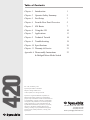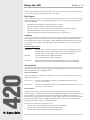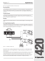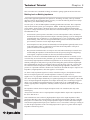
1
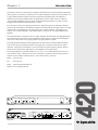
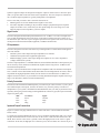
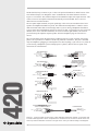
420 User’s Guide
420 Stereo Power Amplifier
Table of Contents
Chapter 1
Introduction
1
Chapter 2
Operator Safety Summary
2
Chapter 3
Fast Setup
3
Chapter 4
Front & Rear Panel Overview
5
Chapter 5
420 Basics
7
Chapter 6
Using the 420
10
Chapter 7
Applications
13
Chapter 8
Technical Tutorial
16
Chapter 9
Troubleshooting
19
20
Chapter 11 Warranty & Service
21
Appendix A Disassembly Instructions
& Bridged-Mono Mode Switch
23
420
Chapter 10 Specifications
Rev A.00, 25 February, 1999
Symetrix part number 53420-0A00
Subject to change without notice.
©1999, Symetrix, Inc. All right reserved.
Symetrix is a registered trademark of Symetrix, Inc.
Mention of third-party products is for informational
purposes only and constitutes neither an endorsement nor
a recommendation. Symetrix assumes no responsibility
with regard to the performance or use of these products.
Under copyright laws, no part of this manual may be
reproduced or transmitted in any form or by any means,
electronic or mechanical, including photocopying,
scanning, recording or by any information storage and
retrieval system, without permission, in writing, from
Symetrix, Inc.
6408 216th St. SW
Mountlake Terrace, WA 98043 USA
Tel (425) 778-7728
Fax (425) 778-7727
Email [email protected]
Chapter 1
Introduction
The Symetrix 420 is a two-channel power amplifier intended for use in professional and commercial
audio systems. The 420 may be operated as a two channel amplifier with 20-watts per channel, or as
a single channel amplifier capable of 40-watts output (mono-bridged mode). The amplifier is
intended for use with near-field monitors, small speakers used for “radio reference” audio-forvideo, and with headphones. In stereo mode, the minimum load impedance is 4 ohms, in monobridged mode the minimum load impedance is 8 ohms.
For convenience, the 420 is equipped with both 1/4" TRS (tip-ring-sleeve) and XLR connectors,
which accept either balanced or unbalanced signals. The 420 produces full output with a 0.5V input
signal (balanced or unbalanced). The 420 can be used as a stereo amplifier, with ganged level
controls, as a 2-channel amplifier, with independent level controls, or as a single-channel mono
amplifier.
The front-panel MODE switch mixes the two inputs together. Broadcast and recording applications
can use this feature to check the mono compatibility of their signals. Commercial sound applications can use this feature to mix paging signals or paging and music signals.
In recording studios and other similar applications, the 420 makes an ideal headphone amplifier.
You can drive one pair of phones from the front-panel jack, or many pairs from the rear-panel
terminals. A front panel switch allows you to turn off the rear-panel speaker terminals, which is
useful for near-field monitor applications or for headphone driver applications.
We recommend that you read this manual cover-to-cover. You will find the answers to most of
your questions inside. Should you have any comments or questions, please do not hesitate to
contact us at the numbers/addresses below. Your calls are always welcome.
Phone: (425) 778-7728
Fax:
(425) 778-7727
Email:
[email protected]
CHANNEL 1
4
5
6
3
STEREO POWER
AMPLIFIER
8
1
MONITOR
STEREO
HEADPHONES
6
7
2
MONO
STEREO
POWER
SPEAKER
MUTED
ACTIVE
8
1
9
0
10
5
3
CLIP
9
0
MODE
GAIN
4
DUAL TRACKING
INDEPENDENT
7
2
CLIP
CHANNEL 2
GAIN
CONTROLS
GAIN
420
420
Website:www.symetrixaudio.com
10
Front panel
100 WATTS MAXIMUM
TYPICAL INPUTS
TIP
=HIGH(+)=
RING
=LOW(-)=
SLEEVE =GROUND=
FUSE
2
CHANNEL
1
1
INPUT 2
INPUT 1
UNBALANCED/
BALANCED
UNBALANCED/
BALANCED
3
FUSE
MANUFACTURED IN
SEATTLE WASHINGTON,
UNITED STATES OF AMERICA
OUTPUTS
CHANNEL
2
PIN 2
PIN 3
PIN 1
SLEEVE
RING
TIP
20 WATTS PER CHANNEL 8 OHMS (CLASS 2 WIRING)
BALANCED
BALANCED
Rear panel
1
Operator Safety Summary
Equipment Markings
CAUTION
RISK OF ELECTRIC SHOCK
DO NOT OPEN
TO REDUCE THE RISK OF FIRE OR
SHOCK DO NOT EXPOSE
WARNING: ELECTRIC
THIS EQUIPMENT TO RAIN OR MOISTURE
DE CHOC ELECTRIQUE
AVIS: RISQUE
NE PAS OUVRIR
SEE OWNERS MANUAL. VOIR CAHIER D’INSTRUCTIONS.
No user serviceable parts inside. Refer servicing to qualified service personnel.
Il ne se trouve a l’interieur aucune piece pourvant entre reparée l’usager.
S’adresser a un reparateur compétent.
The lightning flash with arrowhead symbol within an
equilateral triangle is intended to alert the user of the
presence of uninsulated “dangerous voltage” within
the product’s enclosure that may be of sufficient
magnitude to constitute a risk of electric shock to
persons. The exclamation point within an equilateral
triangle is intended to alert the user of the presence of
important operating and maintenance (servicing)
instructions in the literature accompanying the
product (i.e. this manual).
Caution
the
with
other
fully
To prevent electric shock, do not use
polarized plug supplied with the unit
any extension cord, receptacle, or
outlet unless the blades can be
inserted.
Terms
Several notational conventions are used in this
manual. Some paragraphs may use Note, Caution,
or Warning as a heading. Certain typefaces and
capitalization are used to identify certain words.
These are:
420
Note
Caution
Warning
CAPITALS
Boldface
Identifies information that needs
extra emphasis. A Note generally
supplies extra information to help
you to better use the 420.
Identifies information that, if not
heeded, may cause damage to the
420 or other equipment in your
system.
Identifies information that, if
ignored, may be hazardous to your
health or that of others.
Controls, switches or other markings
on the 420’s chassis.
Strong emphasis.
Important Safety Instructions
Please read and keep these instructions. Heed
and follow all warnings and instructions.
Install in accordance with the manufacturer’s
instructions.
Power Source This product is intended to
operate from a power source that does not apply
more than 250V rms between the power supply
conductors or between either power supply
conductor and ground. A protective ground
2
Chapter 2
connection, by way of the grounding conductor
in the power cord, is essential for safe operation.
Grounding The chassis of this product is
grounded through the grounding conductor of
the power cord. To avoid electric shock, plug the
power cord into a properly wired receptacle
before making any connections to the product. A
protective ground connection, by way of the
grounding conductor in the power cord, is
essential for safe operation. Do not defeat the
safety purpose of the grounding plug. The
grounding plug has two blades and a third
grounding prong. The third prong is provided for
your safety. When the provided plug does not fit
your outlet, consult an electrician for replacement
of the obsolete outlet.
Danger from Loss of Ground If the protective
ground connection is lost, all accessible conductive parts, including knobs and controls that may
appear to be insulated, can render an electric
shock.
Proper Power Cord Use only the power cord
and connector specified for the product and your
operating locale. Use only a cord that is in good
condition. Protect the power cord from being
walked on or pinched, particularly at plugs,
convenience receptacles, and the point where
they exit from the apparatus.
Proper Fuse The user accessible fuse is a part of
the IEC AC inlet connector. The fuseholder
accepts 5 x 20mm diameter fuses. For 117VAC
operation, the correct value is 1.0A, 250VAC,
slow blowing. For 230VAC operation, the correct
value is 0.5A, 250VAC, slow blowing.
Operating Location Do not operate this equipment under any of the following conditions:
explosive atmospheres, in wet locations, in
inclement weather, improper or unknown AC
mains voltage, or if improperly fused. Do not
install near any heat source such as radiators,
heat registers, stoves, or other apparatus
(including amplifiers) that produce heat. Unplug
this apparatus during lightning storms or when
unused for long periods of time.
Stay Out of the Box To avoid personal injury (or
worse), do not remove the product covers or
panels. Do not operate the product without the
covers and panels properly installed. Only use
accessories specified by the manufacturer. Clean
only with a damp cloth.
User-serviceable parts There are no user
serviceable parts inside the 420. In case of failure,
refer all servicing to the factory. Servicing is
required when the 420 has been damaged in any
way, such as when a power supply cord or plug
is damaged, liquid has been spilled or objects
have fallen into the apparatus, the apparatus has
been exposed to rain or moisture, does not
operate normally, or has been dropped.
Fast Setup
Chapter 3
Fast Setup
Follow these instructions to get your 420 up-and-running as quickly as possible. The intent of this
section is fast setup. Refer to later chapters for explanation of the 420’s controls and functions.
Connections
Connect your input source to the either the XLR connectors or to the TRS phone jacks. Connect
the 420’s output to the loudspeakers (or other load) using the barrier strip connector located at the
rear of the unit. If the 420 is driving a headphone distribution system, you’ll get better results (read
louder) if you use the screw terminals on the rear of the unit. The front-panel headphone jack is
really only intended to drive one pair of ‘phones.
OUTPUTS
CHANNEL
2
CHANNEL
1
INPUT 2
INPUT 1
UNBALANCED/
BALANCED
UNBALANCED/
BALANCED
20 WATTS PER CHANNEL 8 OHMS (CLASS 2 WIRING)
BALANCED
BALANCED
2 3 1
2 3 1
Figure 3-1. 420 generic hookup diagram.
Caution
Failure to connect the 420 to the proper AC mains voltage may cause fire and/or
internal damage. There are no user serviceable parts inside the chassis. Refer all
service to qualified service personnel or to the factory.
Warning
Lethal voltages are present inside the chassis. There are no user serviceable parts
inside the chassis. Refer all service to qualified service personnel or to the factory.
420
Connect the AC input to an AC power source of the proper voltage and frequency, as marked on
the rear of the unit.
Settings
Set the controls and switches on the front and rear panel as follows:
Front Panel Control
Setting
Rear Panel Connectors
Connect
CHANNEL 1 GAIN
9:00 o’clock
Outputs
Connect loudspeakers,
headphone distribution
system, or other load.
CHANNEL 2 GAIN
9:00 o’clock
Input 2
Connect balanced or
unbalanced source here.
MODE
Out/Stereo
Input 2
Connect balanced or
unbalanced source here.
SPEAKER MUTE
Out/Active
POWER
In/On
3
Initial Setup
The 420’s controls and switches are now set according to the preceding section. All connections
listed in the settings table on the previous page are now made. The 420 should now pass signal.
The amplifier’s CLIP indicators should not be illuminated.
Generally speaking, the gain controls on a power amplifier should be operated at as high a setting
as possible. This ensures sufficient amplifier sensitivity that the preceding unit can drive the
amplifier into clipping. If the gain controls are turned down sufficiently, it is possible to either clip
the balanced input buffer amplifiers or to cause the preceding unit to clip.
420
With the signal level of the source at a reasonable level, increase the gain of the 420 until either the
CLIP indicators illuminate or the acoustical output of the loudspeakers is sufficient.
4
Chapter 4
Front & Rear Panel Overview
STEREO POWER
AMPLIFIER
4
5
3
8
1
9
0
10
Channel 1
CLIP LED
GAIN
GAIN CONTROLS switch
Channel 2
CLIP LED
GAIN
Mode
MONO / STEREO
Monitor
STEREO HEADPHONES
SPEAKER MUTE
Power
SWITCH
LED
MODE
5
6
3
CLIP
MONITOR
STEREO
HEADPHONES
GAIN
4
DUAL TRACKING
INDEPENDENT
7
2
CLIP
CHANNEL 2
GAIN
CONTROLS
6
MONO
STEREO
7
2
POWER
SPEAKER
MUTED
ACTIVE
8
1
9
0
10
Indicates the onset of clipping at the output of the 420.
Controls the gain, or input sensitivity, of the 420. A volume control by
any other name. This control is active regardless of the 420’s operating
mode. Refer to the DUAL TRACKING / INDEPENDENT switch for more
information.
In DUAL TRACKING mode, the gain control for channel 1 sets the gain for
both channels. The inputs are still separate, there’s just one control for
both channels. Use this mode for stereo applications.
In INDEPENDENT mode, the gain controls for both channels are separate.
Indicates the onset of clipping at the output of the 420.
Controls the gain, or input sensitivity, of channel 2 of the 420. A volume
control by any other name. This control is active only in I NDEPENDENT
mode.
In STEREO mode, both channels of the 420 are separate. In MONO mode,
both inputs of the 420 are mixed (ahead of the GAIN controls).
¼ in. TRS jack. Connect stereo headphones here. This jack will drive
headphones of any impedance, from 4 ohms and up.
Mutes (disconnects) the rear-panel OUTPUT terminals.
Turns the 420 on.
Indicates the presence of AC power.
420
CHANNEL 1
GAIN
420
5
100 WATTS MAXIMUM
TYPICAL INPUTS
TIP
=HIGH(+)=
RING
=LOW(-)=
SLEEVE =GROUND=
FUSE
2
SERIAL NUMBER
AC POWER INPUT
FUSE
OUTPUTS
INPUT 2
INPUT 1
420
MONO BRIDGE switch
6
CHANNEL
1
1
INPUT 2
INPUT 1
UNBALANCED/
BALANCED
UNBALANCED/
BALANCED
3
FUSE
MANUFACTURED IN
SEATTLE WASHINGTON,
UNITED STATES OF AMERICA
OUTPUTS
CHANNEL
2
PIN 2
PIN 3
PIN 1
SLEEVE
RING
TIP
20 WATTS PER CHANNEL 8 OHMS (CLASS 2 WIRING)
BALANCED
BALANCED
[Please send in the completed warranty card.]
IEC-power connector. Connect only to appropriate AC power source.
Refer to rear-panel marking for correct AC source value.
1Ampere Slow-blow fuse. Replace only with same type of fuse 117V ac:
1A, 250V AC, slow blowing (Bussman type MDL-1) 230V AC: 0.5A,
250V ac, slow blowing (Bussman type GDC-500ma).
#6 screw terminals. This is the output of the 420. These terminals may be
turned on/off via the front-panel SPEAKER MUTE switch. For stereo or 2channel applications, connect one load to the channel 1 output and
connect the other load to the channel 2 output. The minimum load
impedance is 4-ohms. For mono-bridge applications, connect the
positive load connection to the channel 1 + output terminal, connect the
negative load connection to the channel 2 + output terminal. The
minimum load impedance is 8-ohms.
XLR-female (pin-2 hot) paralleled with TRS phone jack.
XLR-female (pin-2 hot) paralleled with TRS phone jack. Use this input
for mono-bridge applications.
Located internally.
Chapter 5
420 Basics
Although power amplifiers are one of the basic building blocks of any audio system, they still
remain one of the least understood. Why is minimum load impedance important? What really
happens when you mono-bridge an amplifier? Do you really need a BIG amplifier to run headphones in your studio? We’ll try to answer these questions, and more, in this chapter.
What is a Power Amplifier? A power amplifier is one capable of delivering significant amounts of
power to its load. Power is a measure of energy, which is the ability to do work (like move a
loudspeaker cone or heat up dummy load resistors). Power is measured in watts, which is defined
as the product of voltage times amperage. One watt is one watt, regardless if it is the result of a
current flow of one volt and one ampere (amp), or 10 volts and 0.1 ampere.
P=IE where: P = power in watts, I = current in amperes (amps), and E = electromotive force in volts.
Why is this important? Only because loudspeakers are relatively inefficient devices, and as such,
require significant amounts of power to make them operate. Thus, an 8-ohm loudspeaker will
require 2.82 volts at 0.35 amps to drive it with a one-watt input.
Amplifier Output Limitations
All amplifiers have limitations to their output. Since output power is determined by the voltage and
current that the amplifier can deliver to the load (power is volts times amps), the amplifier’s power
supply voltage determines the maximum voltage that the amplifier can deliver to any load, and the
power supply current capacity combined with amplifier circuit limitations determines the maximum
current that can be delivered to any load.
The relationships between volts, amps, impedance, and watts is stated as follows:
E = IR
where: E = electromotive force in volts, R = resistance or impedance in ohms,
I = current in amperes, and P = power in watts.
E = PR
Using simple algebra, you can manipulate these equations to solve for any
combination of known and unknown variables.
For example:
Make
Symetrix
Crown
Crest
Model
420
DC-300AII
8001
Watts
20
295
1400
Minimum
Load
4
4
2
Output (Volts)
8.94
34.35
52.92
Output (Amps)
2.23
8.59
26.45
Reaching an amplifier’s voltage limitation results in clipping. Reaching an amplifier’s internal
current limit usually results in clipping which is caused by the activation of the amplifier’s internal
protection circuitry. Without protection circuitry, or at least some sort of current limiting, lower
load impedances mean increasing current, and upon exceeding the amplifier’s maximum current
rating, smoke as the unit self-immolates.
For solid-state amplifiers, operating without any load connected or with a load whose impedance is
higher than the amplifier’s rated minimum is harmless. Of course, there is a price, and that price is
diminished power output. As the load impedance doubles, output power halves (this is a best-case
scenario and depends on actual circuit design). Thus, an amplifier having a 50-watt, 8-ohm, power
rating would only deliver 25 watts into a 16-ohm load.
Since output power increases as load impedance decreases (assuming that the voltage remains the
same or nearly the same), operating an amplifier into the lowest possible impedance results in the
7
420
What this means is that the impedance of a loudspeaker and the ability of an amplifier to drive it are
intimately related to the amplifier’s output power, and the amount of voltage and current that it can
deliver to a load (the loudspeaker). If both voltage and current are limited (and they are), the load
resistance must remain above some minimum value: the amplifier’s minimum load impedance. The
minimum load impedance, combined with the output power rating, defines the maximum values of
voltage and current that the amplifier can deliver to its load.
maximum power output. Taking this to its illogical conclusion, an amplifier capable of delivering 20
volts into any load impedance would deliver 50 watts into an 8 ohm load. This same amplifier would
deliver 800 watts into a 0.5-ohm load. Obviously, you can’t do this to most (99%) amplifiers. The
limiting factor is the maximum current that the amplifier can deliver. At 8 ohms, 50 watts corresponds to 2.5 amps. At 0.5 ohms, 800 watts (20V into 0.5 ohms) corresponds to 40 amps! The
minimum load impedance is just another way of stating an amplifier’s maximum current output.
Operating a solid-state amplifier below its rated minimum load impedance can do anything from
nothing (if the amplifier is well protected and/or extremely underrated) to triggering smoke alarms.
A good rule-of-thumb is DON’T operate any amplifier below its rated minimum load impedance.
The minimum load impedance of the 420 is 4 ohms in stereo or dual-mono mode and 8 ohms in
mono-bridged mode.
Mono-Bridged Operation
Mono-bridged operation is a common method of increasing the power delivered to the load.
Bridging requires two amplifier channels and for many amplifiers (but not the 420) translates into
either four times the power of a single channel into the same impedance or twice the single-channel
power into twice the impedance.
Using two amplifier channels to drive both sides of the load simultaneously (usually, one side of
the load is grounded) increases the voltage developed across the load. Paralleling the inputs and
connecting the load across the two output channels doesn’t work because both ends of the load
are driven in the same direction; there is no voltage across the load. Leaving the output connections alone and inverting the polarity of one amplifier channel causes one end of the load to swing
positively, the other end swings negatively. Thus, the voltage across the load is twice what it
would be if the load had one side grounded, which results in four times the power (since the power
increases in proportion to the square of the voltage).
As far as the amplifier is concerned, each channel drives an equivalent load equal to one-half of
the load impedance. An 8 ohm load, connected across the two amplifier channels results in each
amplifier channel seeing the equivalent of a 4-ohm load.
420
Few users recognize the fact that neither side of the load is grounded when you mono-bridge a
stereo amplifier. This means that if you use TS (tip-sleeve) phone plugs for speaker connectors
(and lots of folks do), the shell of the plug, which is usually grounded, is not grounded. If the plug
should come in contact with a microphone (perhaps via its stand...) it is quite possible for the
entire sound system to immediately oscillate, usually at full power, which is not healthy for
loudspeakers and living things. If you operate any amplifier in mono-bridged mode, take steps to
ensure that neither of the output connections can come in contact with ground, themselves, or
anything else.
Driving Loudspeakers
Considering the modest output power of the 420, there isn’t much to say here. If you are driving
multiple speakers (per channel), ensure that the combined impedance of all speakers is 4 ohms or
greater (per channel).
For multiple speakers, parallel connection is preferable to series connection. Loudspeakers
connected in series do not perform the same as the same loudspeakers connected in parallel 1. Do it
if you must, but only if you must.
A Word About Wire
We’re not going to debate the pros and cons of deuterium-enhanced, 99.999+% purity saturnian
copper litz wire here (wider soundstage, glows in the dark, out-of-this-world high end, $2x10 6 per
meter). Instead, how about one paragraph’s worth of common sense?
Even for a twenty watt amplifier, your speaker wire should be reasonably large. At a minimum, 188
gauge zip cord works just fine. If you can, 14-gauge wire is even better. Use godzilla-cable if you
want. The biggest single thing you can do for your loudspeakers when you pick a cable for them is
to minimize the wire resistance. Aside from using silver (which has higher conductivity than
copper), sheer physical size is the way to fly. Remember: the longer the length of speaker wire, the
more important the wire size becomes.
Driving Headphones
Driving headphones is no great feat. Getting them loud can be accomplished two ways: money and
science. The money method is simple: buy a big amplifier. If it isn’t loud enough, buy a bigger
amplifier. Repeat as long as there is money.
The scientific method starts with a volume requirement, and works backward towards the amplifier.
To be truly successful (without an unlimited budget), you need to consider the sensitivity of your
headphones before you buy them.
Usually, what most folks want is LOUD. The way you get LOUD is to increase the amount of power
delivered to the headphones. There are two fundamentally different types of headphones: high
impedance and low impedance. For the purposes of this discussion, high impedance is defined as
600 ohms or higher, and low impedance is defined as 200 ohms or lower. Fortunately, there aren’t
many headphones (that are popular in studios) in the in-between region.
Now you should realize that although most of these ‘phones say “8 ohms” somewhere or another,
what they really mean is “suitable for 8-ohm outputs,” or “these headphones are sensitive enough
to be driven from an 8-ohm output that normally drives loudspeakers.”
The Great Gain Control Mystery
The gain/volume controls found on amplifiers are another object of misunderstanding. For the
record, the gain control on an amplifier inserts an adjustable amount of loss (attenuation) into the
signal path.
Given a constant input signal, varying this loss varies the overall gain, which varies the output
signal level, which amounts to changing the output power, which changes the volume (yes!).
420
Note the phrase, “Given a constant input signal.” This means that a given amount of loss, introduced via the gain control, can be overcome by increasing the input signal by the same amount.
This destroys the myth that reducing the gain setting somehow reduces the power output capability of the amplifier. The gain control reduces the gain of the amplifier or reduces the input sensitivity of the amplifier. The maximum possible output level is the same, regardless of the setting of the
control, as long as some signal gets through.
The setting of an amplifier’s gain control affects only the amplification factor of the amplifier and
has no bearing or effect on the amplifier’s maximum output capability.
1
When two loudspeakers are connected in series, each speaker “sees” the impedance of the
other speaker as its source impedance. Since damping factor is the load impedance divided by the
source impedance, in effect the damping factor seen by each speaker is unity. The fact that a
loudspeaker’s impedance is anything but resistive only complicates matters.
9
Using the 420
Chapter 6
This section is intended for more advanced users. If you are a first-time user, we recommend that
you start out by using the procedure found in “Fast Setup.”
Block Diagram
On the following page you can find the block diagram for the 420. Please take a moment and take
note of the following:
•
•
•
•
•
The balanced input amplifiers are ahead of the GAIN controls.
The TRS and XLR connectors are paralleled with each other.
The SPEAKER MUTE switch does not affect the front-panel STEREO HEADPHONES jack.
The front-panel MONO switch is ahead of the two GAIN controls.
The mono-bridge mode switch is located internally (refer to Appendix A).
Installation
The 420 may be installed freestanding or rack mounted. Multiple amplifier installations should
allow breathing space between each amplifier. Single amplifier installations should strive to keep
the vent holes in the amplifier’s top and bottom clear of obstructions by at least one rack-space
(1.75 inches).
Installation Requirements
Mechanical
One rack space (1.75 inches) required, 12.5 inches depth (including connector
allowance). Rear chassis support recommended for road applications. Allow at
least one empty rack-space above and below the unit for ventilation.
Electrical
117V AC nominal, 60 Hz, 100 Watts maximum.
230V AC nominal, 50 Hz, 100 Watts maximum.
Connectors
XLR-3 female for inputs. Pin 2 of the XLR connectors is “Hot.” TRS female
connectors are also provided. The XLR and TRS connectors are paralleled.
Operating Modes
The 420 has several different operating modes allowing changes in how the GAIN controls operate,
mono operation, and mono-bridged operation.
420
Gain Control Options
The gain controls may be operated two different ways: DUAL TRACKING and INDEPENDENT. These
modes differ as follows:
DUAL TRACKING The gain of both amplifier channels is controlled simultaneously by the
CHANNEL 1 GAIN control.
INDEPENDENT
The gain of each amplifier channel is controlled independently by the C HANNEL 1
and CHANNEL 2 GAIN controls.
Mono and Stereo
The MONO/STEREO MODE switch, located on the front panel, selects between mono and stereo
operation. In STEREO mode, the 420 operates as two independent amplifiers. In mono mode, the two
input channels are mixed and the mix routed to both channels. The proportions of the mix are
determined by the input signal levels (not the two gain controls). The two GAIN controls determine
the output level of their respective outputs. The MONO/STEREO switch is isolated from the input
jacks (its position has no effect on signals at the jacks).
You can use the mono/stereo switch three ways:
• To mono-sum a stereo input signal to check for mono compatibility.
• To mono-sum two unrelated signals (like paging and music).
• To drive both amplifier channels with the same input signal.
10
11
PRESS
(SHOWN STEREO)
MODE
SWITCH
CHANNEL 1
GAIN
INTERNAL ON PCB
(SHOWN AS STEREO)
MONO BRIDGE
SWITCH
INDEPENDENT
DUAL TRACKING
GAIN
CONTROLS
OFFSET NULL
SERVO
OFFSET NULL
SERVO
Figure 6-1. Overall block diagram
CHANNEL 2
GAIN
420
INPUT 2
UNBALANCED/
BALANCED
INPUT 2
BALANCED
INPUT 1
UNBALANCED/
BALANCED
INPUT 1
BALANCED
PRESS
CLIP
CLIP
SPEAKER
MUTE
100 ohms
100 ohms
(SHOWN MUTED)
REV-B
TIP=CHANNEL 1
RING=CHANNEL 2
STEREO
HEADPHONES
(4 ohms MINIMUM)
CHANNEL 2
+ OUTPUT
CHANNEL 2
- OUTPUT
CHANNEL 1
- OUTPUT
CHANNEL 1
+ OUTPUT
Mono-Bridge Mode
As described in Chapter 5, mono-bridge mode uses both amplifier channels to deliver 40 watts into
a single 8 ohm load. Some important things to remember:
•
Both sides of the load (loudspeaker) are driven. There is no “ground” as far as the
loudspeaker is concerned.
•
Any connectors used between the amplifier and the speaker(s) should be insulated so that
neither side of the connector can accidentally contact ground, the other conductor, or any
other conductor. Ordinary phone plugs are especially problematic in this application (since the
design of the plug exposes both conductors and the two conductors are momentarily shorted
together when the plug is inserted or withdrawn).
To avoid inadvertent operation, the mono-bridge switch is located internally; the top cover must
be removed to alter the switch setting. Refer to Appendix A for setting instructions.
In mono-bridge mode, use the CHANNEL 1 INPUT, and connect the speaker across the two plus (+)
output terminals. The channel 1 plus output terminal is the in-phase or non-inverting output
connection (connect it to the plus side of the speaker). Only the CHANNEL 1 GAIN control is
functional. If you connect a pair of headphones to the front panel STEREO HEADPHONES jack, they
will receive out-of-phase signals (not harmful to anything except phase or polarity fanatics).
420
In mono-bridge mode, the 420 delivers 40 watts into an 8 ohm load. The minimum load impedance is
8 ohms.
12
Chapter 7
Applications
Here are a few applications that the 420 lends itself to.
Recording Studios
This is probably the primary use for the 420. Use it to drive the Auratones or the small home-stereo
reference speakers. The 420 probably isn’t powerful enough to drive most near-field monitors
except in very small studios. You can also use the 420 to drive your headphone distribution system
(see below).
Commercial Sound
In commercial sound installations, use the 420 to operate a local system monitor speaker, or to
operate highly-divided zone paging systems. In a church, the 420 can drive a wired hard-of-hearing
system or simultaneous translation system.
Broadcast
Use the 420 to drive the booth monitors, or to ensure that the headphones are loud enough to draw
blood.
No Fooling Distribution Amplifier
REV-B
Figure 7-1. Distribution amplifier wiring
Ensure that the unit is operating in bridged mono mode. You can drive 37 isolated output connections this way, each to a level of approximately +23.5 dBm. Shorting any one output has no effect
on the remainder.
For driving long lines, put the unit into bridged mono mode. Drive the line (balanced, of course) from the
two plus output connections. Tie the ground from the balanced line to either of the minus output
connections. At the other end of the line, you may need to terminate the line with a resistor. It may also
be necessary to build-out the output impedance of the unit at the sending end. This depends on the
nature of the line itself, and whether or not there are transformers or repeat coils involved.
13
420
In applications requiring driving extremely long lines, or an extremely large number of outputs, the
420 performs well. In bridged mono mode, the 420 delivers at least +27 dBm into a 600 ohm balanced
load. For distribution amplifier applications, refer to Figure 7-1.
Headphone Distribution Systems
The 420 is ideally suited to headphone distribution systems. There are two basic strategies
involved in making a loud headphone system:
1.
If you have low impedance phones, then you need high current capability to make them loud.
This translates to a modest 8 ohm power rating, like 20 watts.
2.
If you have high impedance phones, then you need high voltage capability to make them loud.
This translates to a moderate 8 ohm power rating, like 100 watts.
Although the low impedance phones generally get louder, you can’t hang as many (as the high
impedance guys) on your headphone amplifier because sooner or later you arrive at the amp’s
minimum load impedance. This probably isn’t too serious a limitation unless you are into recording
orchestras or other large groups live, using one mix.
420
Figure 7-2 shows a typical distribution box. In a typical studio, there might be four or five of these
boxes sprinkled hither and yon throughout the studio. Each box has four headphone jacks on it
(you’re welcome to add more) and interconnects to the headphone system using mic cables.
Figure 7-2. A simple headphone distribution box
14
We use mic cables for this application because there are usually more mic cables hanging around
the average studio than anything else. TRS plugs or stereo phone plugs short their tip and ring
connections momentarily as they are mated or unmated. This can be harmful to the 420 (most other
amplifiers, too). Figure 7-3 shows the connections needed at the amplifier end. Notice that all
connectors are simply wired in parallel. Take special pains to ensure that pin 1 of the connectors
remains isolated from the system ground (except via the 420).
RIGHT(+)
LEFT(+)
COMMON(-)
RIGHT(+)
LEFT(+)
COMMON(-)
3 2 1
3 2 1
ADDITIONAL
CONNECTIONS
AS REQUIRED
REV-A
Figure 7-3. Amplifier connections for headphone distribution system
The resistors shown in Figure 7-2 isolate the jacks from each other, protect the phones somewhat,
and (most importantly) protect the amplifier from shorted cables and channel-to-channel shorts
(which occur whenever you plug in or unplug a set of phones). Pick the resistor value according to
the impedance of the headphones found in your studio. The maximum number of headphones that
can be driven at once depends on the headphone impedance and the amplifier’s minimum load
impedance. The table below lists maximum quantities for the headphones shown.
Headphones
Maximum #
4 Ohm total load
Max SPL
4 Ohm total load
Maximum #
8 Ohm total load
Max SPL
8 Ohm total load
K240
175
122
87
125
Pro 4X
41
135
20
138
HD424
525
118
212
121
MDR-7506
21
134
10
137
420
You can add volume controls and channel switching to the box if you want, but those details are
beyond the scope of this (short) discussion.
15
Technical Tutorial
Chapter 8
This section discusses a multitude of things, all related to getting signals in and out of the 420.
Matching Levels vs Matching Impedances
In any audio equipment application, the question of “matching” inevitably comes up. Without
digging a hole any deeper than absolutely necessary, we offer the following discussion to (hopefully) clarify your understanding of the subject.
Over the years, we have all had impedance matching pounded into our heads. This is important
only for ancient audio systems, power amplifiers, and RF. Technically speaking, the reason is
power transfer, which reaches a maximum when source and load are matched. Modern audio
systems are voltage transmission systems and source and load matching is not only unnecessary,
but undesirable as well.
•
Ancient audio systems operate at 600 ohms (or some other impedance value), and must be
matched, both at their inputs and at their outputs. Generally speaking, if you are dealing with
equipment that uses vacuum tubes, or was designed prior to 1970, you should be concerned
about matching. These units were designed when audio systems were based on maximum
power transfer, hence the need for input/output matching.
•
Power amplifiers are fussy because an abnormally low load impedance generally means a visit
to the amp hospital. Thus, it’s important to know what the total impedance of the pile of
speakers connected to the amplifier really is.
•
RF systems are matched because we really are concerned with maximum power transfer and
with matching the impedance of the transmission line (keeps nasty things from happening).
Video signals (composite, baseband, or otherwise) should be treated like RF.
Some folks seem to believe that balanced/unbalanced lines and impedances are related; or even
worse that they are associated with a particular type of connector. Not so. Unbalanced signals are
not necessarily high-impedance and balanced signals/lines are not necessarily low-impedance.
Similarly, although 1/4-inch jacks are typically used for things like guitars (which are high-impedance and unbalanced), this does not predispose them to only this usage. After all, 1/4-inch jacks
are sometimes used for loudspeakers, which are anything but high-impedance. Therefore, the
presence of 3-pin XLR connectors should not be construed to mean that the input or output is lowimpedance (or high-impedance). The same applies to 1/4-inch jacks.
420
So, what is really important? Signal level, and (to a much lesser degree), the impedance relation
between an output (signal source) and the input that it connects to (signal receiver).
Signal level is very important. Mismatch causes either loss of headroom or loss of signal-to-noise
ratio. Thus, microphone inputs should only see signals originating from a microphone, a direct (DI)
box, or an output designated microphone-level output. Electrically, this is in the range of approximately -70 to -20 dBm. Line inputs should only see signals in the -10 to +24 dBm/dBu range.
Guitars, high-impedance microphones, and many electronic keyboards do not qualify as line-level
sources.
The impedance relation between outputs and inputs needs to be considered, but only in the
following way:
Always make sure that a device’s input impedance is higher than the output source impedance of
the device that drives it.
Some manufacturers state a relatively high-impedance figure as the output impedance of their
equipment. What they really mean is that this is the minimum load impedance that they would like
their gear to see. In most cases, seeing a output impedance figure of 10,000 (10K) ohms or higher
from modern equipment that requires power (batteries or AC) is an instance of this type of rating. If
so, then the input impedance of the succeeding input must be equal to or greater than the output
impedance of the driving device.
16
Symetrix equipment inputs are designed to bridge the output of whatever device drives the input
(that is, be greater than 10 times the actual source impedance). The 420’s outputs are intended to
drive 4-ohm or higher impedances, typically loudspeakers or headphones.
The two facts that you need to derive from this discussion are:
1.
2.
Match signal levels for best headroom and signal-to-noise ratio.
For audio, impedance matching is only needed for antique equipment and power amplifier
outputs. In all other cases, ensure that your line inputs bridge (are in the range of 2 to 200
times the output source impedance) your line outputs.
Signal Levels
The 420 is designed around studio/professional line levels: +4 dBu or 1.23 volts. The input sensitivity is high enough that the 420 can be driven to full output with the input gain controls set to
less than wide open. The unit is quiet enough to operate at lower signal levels such as those found
in semipro or musical-instrument (MI) equipment (-10 dBu or 300 millivolts).
I/O Impedances
The 420 is designed to interface into almost any recording studio or sound reinforcement application. This includes:
•
•
•
600-ohm systems where input and output impedances are matched.
Unbalanced semiprofessional equipment applications.
Modern bridging systems where inputs bridge and outputs are low source impedances
(voltage transmission systems).
The 420’s input impedance is 10 kilohms balanced, and 10 kilohms unbalanced. The inputs may be
driven from any source (balanced or unbalanced) capable of delivering at least -10 dBu into the
aforementioned impedances.
The 420’s output is intended to drive loudspeaker or headphone loads. The minimum load impedance is 4 ohms in stereo/dual-channel mode and 8 ohms in mono-bridged mode. Of course, there is
no problem driving high-impedance loads; (the 420 can drive a 600-ohm load to +27 dBm. This
might be useful, for instance, if you needed a no-fooling distribution amplifier capable of driving a
large (even ridiculous?) number of loads simultaneously.
The 420 uses the international standard polarity convention of pin 2 hot. Therefore, if your system
uses balanced inputs and outputs, and uses the 420 this way, then the polarity convention is
unimportant. If your system is both balanced and unbalanced, then you must pay attention to this,
especially when going in and coming out through different connector types (like input on an XLR,
output on a phone jack).
XLR
Pin 1
Pin 2
Pin 3
1/4" Phone
Sleeve
Tip
Ring
Signal
Ground
High
Low
Input and Output Connections
Figure 8-1 (on the next page) illustrates how to connect the 420 to various balanced and unbalanced sources.
To operate the 420 from unbalanced sources, run a 2-conductor shielded cable (that’s two conductors plus the shield) from the source to the 420. At the source, connect the low/minus side to the
shield, these connect to the source’s ground; connect the high/plus side to the source’s signal
connection. At the 420, the high/plus wire connects to pin 2, the low/minus wire connects to pin 3,
17
420
Polarity Convention
and the shield (always) connects to pin 1. This is the preferred method as it makes best use of the
420’s balanced input (even though the source is unbalanced). The other alternative shown in
Figure 8-1 converts the 420’s balanced input into an unbalanced input at the input connector. This
works, but is more susceptible to hum and buzz than the preferred method. There is no level
difference between either method.
The rear-panel output terminals (accept #6 spade lugs or bare wires) are intended to drive loudspeakers or headphone distribution systems. The minimum load impedance is 4-ohms in stereo/
dual-mono mode and 8-ohms in mono bridge mode. If you are driving a headphone distribution
system, ensure that each headphone jack has (at least) a 22-ohm, 5-watt resistor in series with each
channel (one in series with the left channel, one in series with the right channel). The resistors
prevent shorting the amplifier outputs together when the headphone plugs are inserted or removed.
The 1/4 inch output jack on the front panel is a TRS (tip-ring-sleeve) jack wired for stereo headphones. The tip connects to channel 1 and the ring connects to channel 2. This jack is intended
only for headphones (plugging in a loudspeaker won’t hurt anything, it just won’t be very loud). If
you are driving a headphone system (multiple pairs of ‘phones), then use the rear panel screw
connections. It will work better.
TO BALANCED IN
2 31
13 2
FROM BALANCED OUT
FEMALE XLR
PIN 1 = GROUND
PIN 2 = HIGH
PIN 3 = LOW
TO UNBALANCED IN FROM
TRANSFORMER COUPLED OR
FLOATING BALANCED OUTPUT
FROM BALANCED OUT
MALE TRS PLUG
TIP = HIGH
RING = LOW
SLEEVE = GROUND
MALE XLR
PIN 1 = GROUND
PIN 2 = HIGH
PIN 3 = LOW
TIP
MALE TS PLUG
TIP = HIGH
SLEEVE = GROUND +
LOW
RING
SLEEVE
TO BALANCED IN
FROM UNBALANCED OUT
MALE TS PLUG
TIP = HIGH
SLEEVE = GROUND +
LOW
TIP
RING
MALE TRS PLUG
TIP = HIGH
RING = LOW
SLEEVE = GROUND
SLEEVE
TERMINAL STRIP
(+) = HIGH
(-) = LOW
= GROUND
TO BALANCED IN
FROM UNBALANCED OUT
TERMINAL STRIP
(+) = HIGH
(-) = LOW
= GROUND
TERMINAL STRIP
(+) = HIGH
(-) = NOT USED
= GROUND
FROM NON-TRANSFORMER (ELECTRONIC)
BALANCED OUTPUT
(TYPICAL OF SYMETRIX PRODUCTS)
FEMALE XLR
PIN 1 = GROUND + LOW
PIN 2 = HIGH
PIN 3 = NOT USED
2 31
420
FROM BALANCED OUT
TO UNBALANCED IN
MALE TS PLUG
TIP = HIGH
SLEEVE = GROUND +
LOW
REV-B
Figure 8-1. Input and output connector wiring. These diagrams represent the majority of connectors used
in modern audio equipment at line or microphone level. Locate the source connector in the left column and
match it up with the destination connector in the right column. Wire your cable according to the diagrams.
18
Chapter 9
Troubleshooting
Troubleshooting Chart
SYMPTOM
PROBABLE CAUSE
No output
Check cables and connections.
Are inputs driven by outputs, and outputs driving speakers or
headphones?
Are all of the cables good?
Is there signal coming out of the source?
Are the loudspeakers or headphones OK?
Is the front-panel SPEAKER MUTE switch out?
Check for AC power presence. Power LED on?
Check output by plugging headphones into front-panel headphone jack.
Is the fuse OK?
No output in bridge mono Are you using the CHANNEL 1 INPUTS?
SPEAKER MUTE switch out?
Outputs out-of-phase
Hum or buzz in output
Mono bridge switch engaged.
Check input connector wiring (refer to Figure 8-1).
Ground loop. Check related system equipment grounding. Are all system
components on the same AC ground?
Is the hum or buzz coming out of the preceding unit?
Distortion
Check input signal. Is it too hot, or is it already distorted?
Are the input gain controls turned down too far (causing clipping in the
source because it doesn’t have enough output level to overcome the
loss in the input gain controls)?
Are the CLIP LEDs indicating clipping1 ?
Check output loading. Should be above 4 ohms in stereo/2-channel
mode or 8 ohms in mono-bridge mode.
Is something else clipping?
Check input signal levels, and level control settings.
420
Noise (hiss)
Check gain settings on upstream equipment.
Is the input signal already noisy?
Blows fuses
Are the speaker connections shorted?
Disconnect speakers, disconnect inputs, replace fuse, turn unit on. If
the fuse blows immediately, call the factory.
1
The clip LEDs do not indicate clipping caused by the activation of the amplifier’s internal
current limiting circuitry.
19
Specifications
Chapter 10
420 Specifications
Input/Output
Inputs
XLR-Female Paralleled with TRS ¼" jacks
10 kilohms Line-Level Balanced Bridging
Balanced CMRR greater than 55 dB @ 1 kHz
Outputs
Two, 4 Ohms minimum impedance, #6 screw terminals
Maximum Input Level
+21 dBu
Maximum Output (stereo/2-channel)
20 watts RMS,
per channel, into a 4- or 8-Ohm load
Maximum Output (mono bridged) 40 watts RMS into an 8-Ohm load
Minimum Load
4 Ohms, stereo mode;
8 Ohms, monobridged mode
Headphone Output
100-Ohm source impedance,
19V open circuit with speakers off
Performance Data
(measured at 120V AC line voltage)
Frequency Response
20 Hz to 20 kHz (+0, -1 dB)
Crosstalk
>60 dB (22 kHz bandwidth)
Sensitivity
0 dBu for 20 watts into an 8-Ohm load
Maximum Gain
27 dB
Signal to Noise
>95 dB
Typical Distortion
<0.04%, @ 1 kHz, 1 watt into 8 Ohms
THD+Noise
<0.2%, 20 Hz to 20 kHz, @ 20 watts into 8 Ohms
Clip Indicators
One per channel
Physical
Size (hwd)1.72 x 19 x 7.25 inches, 4.37 x 48.26 x 18.415 centimeters
Weight
7.6 lbs (3.5kg) net, 10 lbs (4.6 kg) shipping
Electrical
Power Requirements
120V nominal, 108 to 132V AC,
60 Hz, 100 watts
Note: The maximum operating ambient temperature is 25
degrees C.
In the interest of continuous product improvement, Symetrix, Inc.
reserves the right to alter, change, or modify these specifications
without prior notice.
420 Architects and Engineers Specifications
The power amplifier shall be a compact, two input, two output, high performance, power amplifier.
It shall occupy a single rack space. (1U)
420
The unit shall be capable of delivering 20 watts per channel into a minimum load of 4 Ohms. The
unit shall also have a mono-bridge mode which delivers 40 watts into a minimum load of 8 Ohms.
The inputs shall be active balanced bridging designs terminated with 3-pin XLR (AES/IEC standard
wiring), and ¼" TRS female. The input circuitry shall incorporate RFI filters. The balanced inputs
shall accommodate +24 dBu signals without distortion. Screw terminals shall be provided for power
amplifier outputs.
THD shall not be greater than 0.04%, @ 1 kHz, @ 1 watt in 8 Ohms. Signal to noise ratio shall be
greater than 95 dB. Frequency response shall be 20 Hz to 20 kHz (+0 dB, -1 dB).
The power amplifier shall be protected from output short-circuits. A front panel Dual Tracking
switch shall allow the Channel 1 gain control to simultaneously control the level of both channels.
There shall be a ¼" tip-ring-sleeve jack mounted on the front panel for stereo headphone output. A
front panel switch shall be provided to mute the rear panel output connections. Another front
panel switch shall be provided to sum the two input signals and route them to the two gain
controls.
Independent clipping indicators shall be provided for each output channel.
The amplifier shall be capable of operating by means of its own built-in power supply connected to
120V nominal AC (108 to 132V) 60 Hz.
The unit shall be a Symetrix Incorporated model 420 Stereo Amplifier.
20
Chapter 11
Warranty & Service
420 Limited Warranty
Symetrix, Inc. expressly warrants that the product will be free from defects in material and workmanship for one (1) year. Symetrix's obligations under this warranty will be limited to repairing or
replacing, at Symetrix's option, the part or parts of the product which prove defective in
material or workmanship within one (1) year from date of purchase, provided that the Buyer
gives Symetrix prompt notice of any defect or failure and satisfactory proof thereof. Products
may be returned by Buyer only after a Return Authorization number (RA) has been obtained
from Symetrix. Buyer will prepay all freight charges to return the product to the Symetrix
factory. Symetrix reserves the right to inspect any products which may be the subject of any
warranty claim before repair or replacement is carried out. Symetrix may, at its option, require
proof of the original date of purchase (dated copy of original retail dealer's invoice). Final
determination of warranty coverage lies solely with Symetrix. Products repaired under warranty
will be returned freight prepaid by Symetrix via United Parcel Service (surface), to any location
within the Continental United States. At Buyer's request the shipment may be returned via
airfreight at Buyer's expense. Outside the Continental United States, products will be returned
freight collect.
The foregoing warranties are in lieu of all other warranties, whether oral, written, express,
implied or statutory. Symetrix, Inc. expressly disclaims any IMPLIED warranties, including
fitness for a particular purpose or merchantability. Symetrix's warranty obligation and
buyer's remedies hereunder are SOLELY and exclusively as stated herein.
This Symetrix product is designed and manufactured for use in professional and studio audio
systems and is not intended for other usage. With respect to products purchased by consumers for personal, family, or household use, Symetrix expressly disclaims all implied warranties, including but not limited to warranties of merchantability and fitness for a particular
purpose.
This limited warranty, with all terms, conditions and disclaimers set forth herein, shall extend
to the original purchaser and anyone who purchases the product within the specified warranty
period.
Symetrix does not authorize any third party, including any dealer or sales representative, to
assume any liability or make any additional warranties or representation regarding this product
information on behalf of Symetrix.
This limited warranty gives the buyer certain rights. You may have additional rights provided
by applicable law.
Limitation of Liability
The total liability of Symetrix on any claim, whether in contract, tort (including negligence) or
otherwise arising out of, connected with, or resulting from the manufacture, sale, delivery,
resale, repair, replacement or use of any product will not exceed the price allocable to the
product or any part thereof which gives rise to the claim. In no event will Symetrix be liable for
any incidental or consequential damages including but not limited to damage for loss of
revenue, cost of capital, claims of customers for service interruptions or failure to supply, and
costs and expenses incurred in connection with labor, overhead, transportation, installation or
removal of products or substitute facilities or supply houses.
21
420
Warranty Registration must be completed and mailed to Symetrix within thirty (30) days of the
date of purchase.
Servicing the 420
If you have determined that your 420 requires repair services and you live outside of the
United States please contact your local Symetrix dealer or distributor for instructions on how
to obtain service. If you reside in the U.S. then proceed as follows:
At the Symetrix factory, Symetrix will perform in-warranty or out-of-warranty service on any
product it has manufactured for a period of five years from date of manufacture.
Before sending anything to Symetrix, contact our Customer Service Department for a return
authorization (RA) number. The telephone number is (425) 778-7728, Monday through Friday,
8AM (800 hours) though 4:30 PM (1630 hours), Pacific Time.
In-Warranty Repairs
To get your 420 repaired under the terms of the warranty:
1.
Call us for an RA number.
2.
Pack the unit in its original packaging materials.
3.
Include your name, address, daytime telephone number, and a brief
statement of the problem.
4.
Write the RA number on the outside of the box.
5.
Ship the unit to Symetrix, freight prepaid.
We do not accept freight collect shipments.
Just do these five things, and repairs made in-warranty will cost you only one-way freight
charges. We'll prepay the return (surface) freight.
420
If you choose to send us your product in some sort of flimsy packaging, we'll have to charge
you for proper shipping materials. If you don't have the factory packaging materials, then do
yourself a favor by using an oversize carton, wrap the unit in a plastic bag, and surround it
with bubble-wrap. Pack the box full of Styrofoam peanuts. Be sure there is enough clearance in
the carton to protect the rack ears (you wouldn't believe how many units are returned with
bent ears). We won't return the unit in anything but Symetrix packaging for which we will have
to charge you. Of course, if the problem turns out to be operator inflicted, you'll have to pay
for both parts and labor. In any event, if there are charges for the repair costs, you will pay for
the return freight. All charges will be COD unless you have made other arrangements (prepaid,
Visa or Mastercard).
Out-of-Warranty Repairs
If the warranty period has passed, you'll be billed for all necessary parts, labor, packaging
materials, and freight charges. Please remember, you must call for an RA number before
sending the unit to Symetrix.
22
Appendix A
Disassembly Instructions & Bridged-Mono Mode Switch
Caution
These servicing instructions are for use by qualified personnel only. To avoid
electric shock do not perform any servicing other than that contained in the
operating instructions portion of this manual unless you are qualified to do so.
Refer all servicing to qualified service personnel.
Warning
Lethal voltages are present inside the chassis. Perform all service work with the
unit disconnected from all AC power.
Top Cover Removal
1.
Ensure that the 420 is disconnected from the AC power source. Disconnect any input or
speaker cables.
2.
Remove four 6-32 x 1/2 inch screws from the rear-panel.
3.
Remove two 6-32 x 1/2 inch screws from each side of the chassis.
4.
Remove one 6-32 x 1/2 inch screw from the top-middle of the front panel. Use caution to
prevent the screwdriver from slipping and marring the front panel.
5.
Remove two 6-32 flat-head screws from the top cover.
6.
Slide the top cover 1 inch towards the rear of the unit, then lift the top cover free of the
chassis.
1.
Ensure that the 420 is disconnected from the AC power source.
2.
Remove the top cover using the procedure described previously.
3.
Unplug the two transformer connectors (one for each printed circuit board).
4.
Remove one screw from each of the four corners of the front panel and one screw in the
bottom-center of the front panel.
5.
Remove the knobs from the front panel. Remove the front panel and set it aside.
6.
Remove four 6-32 x 1/4 inch SEMS machine screws from the main printed circuit board.
7.
Remove the two 6-32 x 1/2 inch machine screws that fasten the IEC connector to the chassis.
8.
Remove two 6-32 SEMS screws that fasten the power supply PCB to the chassis.
9.
Disconnect the green safety ground wire at the chassis screw terminal by removing the nut.
Ensure that this wire is reconnected when reassembling the 420.
10. Remove two screws located on the chassis bottom that secure the heatsink.
11. Lift out both printed circuit boards, taking care not to stress the two voltage regulators or the
ribbon cable that joins the two circuit boards.
Bridged-Mono Mode Switch
To prevent inadvertent setting, the bridged-mono mode switch is located inside of the 420. To set
or reset the switch, use the following procedure.
1.
Disconnect the 420 from the AC power source.
2.
Remove the top cover using the previously described procedure.
3.
Locate the switch, which is situated near the input connectors.
4.
Depress the switch plunger to select mono-bridge mode (plunger remains IN). For stereo mode,
the switch plunger should be OUT.
5.
Replace the top cover and all fasteners previously removed.
23
420
Circuit Board Removal
420
24
Symetrix, Inc.
6408 216th St. SW
Mountlake Terrace, WA, 98043
USA
Tel: (425) 778-7728
Fax: (425) 778-7727
Website: http://www.symetrixaudio.com
Email: [email protected]