1
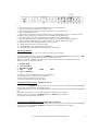
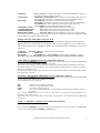
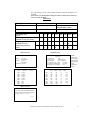
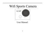
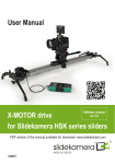
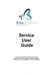
9 Channel Colour Multiplexer
System Q Order No:
CCT286
Instruction manual
System Q Ltd. The Green, Hasland, Chesterfield, S41 0LJ
1
Front and Rear Layout of the Multiplexer CCT286
CCT286d2
Front view of the multiplexer
The on/off switch is on the far left hand side
The camera select switches are shown marked 1-9
The function switches for Quad, Freeze, Playback, Auto etc are on the right hand side
CCT286d4 Rear view of the multiplexer
The BNC sockets on the top row left side are camera inputs 1-9
The BNC sockets underneath them are the video outputs
There is a monitor output socket (labelled 7 on diag. CCT286d4)
VCR in and out sockets (labelled 8 and 9 on diag. CCT286d4)
S-VHS in and out sockets (labelled 10 and 11 on diag. CCT286d4)
2 15 way ‘D’ type connectors:
1 labelled 12 (Remote Control) on diag. CCT286d4
1 labelled 13 (Alarm Contacts) on diag. CCT286d4
To the right of these are the Mains fuse and the Mains input connector (IEC or ‘Kettle lead’)
System Q Ltd. The Green, Hasland, Chesterfield, S41 0LJ
2
What to check for on unpacking the Multiplexer.
Multiplexer with the correct number of camera inputs as ordered.
Instructions for Installation and Operation of the multiplexer
An IEC power lead
Adapter lead (if ordered!) to connect to the Hitachi TLR. Ordered as a separate item.
Connecting to the Multiplexer
CCT286d4
The connections refer to diagram CCT286d4 above.
It is possible to connect up to 9 cameras to the multiplexer. They are connected to the top row of BNC sockets
marked 1-9. It is possible to ‘loop’ the video through the multiplexer by connecting equipment such as
monitors to the output BNC sockets under the input BNC socket on the multiplexer. This in effect Bypasses
the multiplexer and can be used to monitor the video input directly from the cameras.
The monitor connects to the BNC socket labelled MONITOR marked as (7) on the diag. above.
If using a Time Lapse or standard VCR connect the input of the VCR to the output VCR BNC socket on the
multiplexer, labelled VCR and is the bottom BNC socket labelled (9) on the diagram above.
The output from the VCR connects to the VCR input BNC socket on the multiplexer.
It is essential to connect the VCR or TLR this way or it will not be possible to use the multiplexer for
viewing images on the tape being replayed.
When the tape is replayed the multiplexer can be used to view images in single screen mode, multi-screen
mode (Quad or 9 images) or to automatically scan through the screens.
There is also the facility to connect a VCR using S-VHS connectors marked 10 and 11 on the diagram.
The socket marked Remote Control on the multiplexer and labelled 12 is for a Remote Control Keypad that is
available separately. This connector is a 15 way ‘D’ type socket.
The next socket marked Alarm input/output and labelled 13 on the diagram (the top row of pins) is for alarm
sensors. It is possible to have alarm sensors on video sockets 1-8, 9 is not alarmed. (These pins are held at
TTL level 5 volts and to activate they can be linked to 0 volts).
On the bottom pins of the connector labelled 14 is the Trigger input (special function for linking to the Hitachi
TLR see section 2 page 5); the other pins are clean or dry relay contacts to provide an output to external
devices in alarm conditions. (These are standard relay contacts Common, N/O and N/C).
The connector labelled 15 is the mains fuse holder.
The connector labelled 16 is the mains input connector, this is an IEC connector (kettle lead type)
System Q Ltd. The Green, Hasland, Chesterfield, S41 0LJ
3
Diagram CCT286d3
1 = The on/off switch. A red light illuminates when the unit is switched on
2 = These are the single screen select switches 1 to 9
3 = The quad display select switch, push once for cameras 1-5 and twice for 5-8
4 = The 9 screen display switch
5 = The Freeze switch, press once to freeze the picture, press and hold for approx. 3 seconds to access
the Menu screens. (See the next section for more information about the menus).
6 = The Auto select switch will scroll through the available screens automatically.
7 = The PB or playback switch, allows the TLR recording to be viewed through the multiplexer
8 = Frame, pressing and holding this key allows the user to view the TLR or VCR input.
9 = The alarm list key, this displays the alarm events on screen
10 = Alarm sounder reset key, silences the alarm.
11 = The LED light for the Trigger pulse from the TLR
12 = The LED light of the Continuous mode frame rate to the TLR
The Setup Menus
(The numbers in brackets refer to keys labeled on diagram CCT286d3)
To enter the setup menu press and hold the FREEZE key (5) until the OSD appears on the monitor. (OSD =
On Screen Display) See Appendix 1 for displays of the menu screens.
There are 5 screens in total, the one that was last accessed will be the first one displayed next time.
The titles of the screens are as follows:
1.
2.
3.
4.
5.
DATE & TIME
VCR & ALARM
SET DWELL TIME
REC
MON
CH1: “CAMERA.1”
LOAD
ARM
To move the cursor around the menu’s use keys 1, 2, 3, 4
To change any of the information use keys 5 or 6
To move to the next menu screen use key 7
To exit from the setup at anytime press key 9
1 Changing the Date and Time. (Appendix 1 Menu 1)
Press and hold the FREEZE key for 3 seconds to enter the setup screens. Press the 7 key to scroll through the
setup screens until the Date & Time menu appears.
Change the flashing character by using the 5 or 6 key, or move to the character to be changed using the 1 or 4
keys.
Press the 2 or 3 key to move to the Time and adjust in the same way as above.
Press key 3 to move down to the FORMAT and set to EURO using key 5 or 6.
Pressing key 9 exits from the setup menu.
2 VCR & ALARM Menu Screen (Appendix 1 Menu 2)
Press and hold the FREEZE key for 3 seconds to enter the setup screens. Press the 7 key to scroll through the
setup screens until the VCR & ALARM menu appears. To exit from menus press key 9.
The options are as follows:
System Q Ltd. The Green, Hasland, Chesterfield, S41 0LJ
4
VCR INPUT:
BNC or S-VHS (set to BNC if the TLR is connected using the BNC terminals, or
to S-VHS if using the S-VHS connections)
VCR OUTPUT:
TIMELAPS or CONTINUOUS (Set to Continuous if the adapter link cable isn’t
used. This cable is available as a separate item for System Q Hitachi TLR)
REC MODE:
TLV.NORMAL (Time-lapse recording without alarm triggers)
SP ALARM (use with the Continuous setting above, used with alarm triggers)
SP NORMAL (use with Continuous, when no alarm triggers are used)
TLV.ALARM (set to this when alarm triggers are used)
ALARM RELAY TIME:
0-99 (length of time alarm camera event is monitored)
ALARM BUZZER TIME:
0-15 (length of time the buzzer sounds after an alarm)
LOSS BUZZER TIME:
0-15 (length of time buzzer sounds after video loss)
REMOTE ID NUMBER
OFF~0-16 (OFF if only one Multiplexer is in use on the same system)
To change any of the settings press the 3 key to move down the options and press either key 5 or 6 to switch
between them. To exit from menus press key 9.
Settings when the link cable is used for TLR
This section refers to a special cable that can be purchased separately and allows the
Hitachi TLR to be linked with the multiplexer and when the menus are set as follows the
TLR controls and sets the multiplexer frame rate to automatically synchronize between the
2 devices.
VCR INPUT: BNC OR S-VHS (Most TLR’s use BNC connections)
VCR OUTPUT:
TIMELAPS
REC MODE:
TLV.NORM (set to TLV.ALARM when alarm switch recording is required.)
See section 2 above for information about accessing the menu screen relating to the above settings
3 SET DWELL TIME Menu Screen (Appendix 1 Menu 3)
Press and hold the FREEZE key for 3 seconds to enter the setup screens. Press the 7 key to scroll through the
setup screens until the SET DWELL TIME menu appears.
This screen allows the user to change the delay rate for the sequential timing of the monitor switching.
Press the 2 or 3 key to move up and down the screen and press either key 5 or 6 to change any settings.
The values available are 0-15.
(Set any unused camera inputs to the value of 0 for OFF. This prevents blank screens being displayed when
auto switching is selected)
4 The REC MON LOAD ARM Menu Screen (Appendix 1 Menu 4)
Press and hold the FREEZE key for 3 seconds to enter the setup screens. Press the 7 key to scroll through the
screens until the REC MON LOAD ARM menu appears.
The available options are as follows:
REC
MON
LOAD
ARM
= camera to be recorded (ON or OFF)
= camera to be monitored (ON or OFF)
= 75 or HI (see the note below)
= N.O. / N.C. or OFF (Set to N.O. for alarm trigger, alarm will trigger when the contact is
grounded)
Note: - If only camera inputs 1to 9 are used then set the value to 75, if the video loop through feature is to be
used then set the value to HI
Press the 2 or 3 key to move up and down the screen, 1 or 4 to move across and either key 5 or 6 to change
any settings.
5 CH1: “CAMERA.1” Menu Screen (Appendix 1 Menu 5)
(This menu relates to the text displayed)
Press and hold the FREEZE key for 3 seconds to enter the setup screen. Press the 7 key to scroll through the
setup screens until the CH1: “CAMERA.1” Menu appears.
System Q Ltd. The Green, Hasland, Chesterfield, S41 0LJ
5
This is the text that is displayed on the full screen shot of the selected cameras. The text in the speech marks
“*” can be edited as required. There are only 8 characters allowed remembering that full stops etc count as a
single character.
When CH1 is flashing press key 5 or 6 to change to a different channel number.
Pressing key 4 will move the cursor across to the text in speech marks. Highlight the character to be changed
and then press key 5 or 6, the cursor now moves to the lower section of the display. By using keys 1, 2, 3 or 4
replacement characters can be selected, press the key 5 or 6 to change the character and repeat until all the
text has been replaced as required.
Pressing key 7 will change to a different menu, pressing 9 exits from the setup menus.
Alarms/Loss Recall Screen
Pressing the LIST key shows the Alarms/Loss screen. This consists of 16 pages of 8 lines with date and time
information including channel number and what the alarm event was. (L = loss of video, A = alarm)
Date
Time Ch (channel)
- (event = L/A)
Use keys 5 and 6 to scroll up or down through the screens.
Pressing key 8 erases the stored information on the displayed screen.
When all the information has been viewed or erased pressing the LIST key again exits from the menu.
Alarm Contacts.
This is a 15 way ‘D’ type connector.
Pins 1~8 correspond to the cameras and are set at TTL high (5 volts). To activate an alarm these inputs can be
grounded to pin 13, 14 or 15 on the same connector.
When an alarm event takes place the full screen is displayed for a user variable length of time.
Settings to check when using the alarm feature of the unit:
In the VCR & ALARM menu set the REC MODE: to TLV.ALARM
The ALARM RELAY TIME sets the length of time the event is monitored (0-99)
In the REC MON LOAD ARM menu: (Appendix 1 Menu 4)
Check that the REC and MON settings are ON for relevant cameras.
The ARM should be set for N.O.
When the tape is being replayed view alarm events in the Quad display, these can be selected for full screen
viewing in the normal manner, the non-alarmed segments will not be recorded. Should there be an alarm
triggered during playback the relevant screen will be automatically displayed for the set time.
Should there be more than one alarm event then alternate screen shots will be displayed.
When the system reverts back to playback mode a screen will have to be selected for viewing, either one
camera or Quad etc.
All alarm events will be recorded in the log, which can be accessed by pressing the LIST key.
Recording Using a TLR or VCR
The VCR being used must be connected as shown in diagram() if the images are to be manipulated and
viewed using the multiplexer. When images are played back through the multiplexer it is possible to use the
functions on the multiplexer to view single screens of individual cameras or multi screen views i.e. 9-screen
mode.
In menu 2 set the VCR OUTPUT to CONTINUOUS.
When using the multiplexer with a System Q supplied Hitachi TLR and adapter cable set the VCR OUTPUT
in menu 2 to TIMELAPSE. Set REC MODE to TLV-NORMAL if no alarms are used.
Select the VCR input, either BNC or S-VHS according to the connections being used. (refer to diag.
CCT286d)
System Q Ltd. The Green, Hasland, Chesterfield, S41 0LJ
6
Playing Back the Recordings
To playback recordings press the PB switch (labelled (7) on diag. CCT286d3). The red light above the button
will illuminate. Press play on the VCR and then select either one of the full screen switches marked 1-9 or the
multi screen switch marked 9’TH. AUTO can also be chosen so the multiplexer scrolls through the various
screens allowing the user to select any of the available screens when required.
Alarm Relay Contacts
Diagram CCT286d6
There are clean alarm relay contacts available, Common (COM), Normally Open (NO) and Normally Closed
(NC). They are on the 15 way ‘D’ type connector labeled Alarm input/output and their connections are as
follows:
NO = pin 9
Common = pin 10
NC = pin 11
The contact ratings are:
AC 125V @2A
AC 250V @ 1A
The relay changes state when an alarm event occurs, and is switched for the same length of time as set in the
menu for monitoring the camera event. (Alarm Relay Time)
Connections for the Sync Lead
Refer to diagram CCT286d6
Hitachi TLR 15 way ‘D’
Pin 9
to
Pin 15 gnd
to
Multiplex
Pin 12 (trigger on Alarms con)
Pin 15 gnd
Other Keys and Indicators
PB
FRAME
FREEZE
RESET
= Playback, select this and then single, quad or multi screen button for replaying from the
TLR/VCR
= Shows the video feed to the TLR when recording (press and hold) This will display the
Frame rate being sent to the VCR which is a useful indicator that there is a signal going to
the VCR. (Rapidly moving images from the camera inputs)
= Freezes the current displayed picture (unless the picture is showing an alarm event)
Holding this key for more than 3 seconds will allow access to the menus.
= Silences the alarm buzzer
Indicators
VCR Trigger
Middle LED
Continuous
= Indicates the sync pulses when the TLR is recording (flashing red light) only when the
lead is connected and the VCR is recording.
= Constant red light when Play Back is selected
= Indicates that the unit is set for TIMELAPSE on menu 2 (constant red light)
System Q Ltd. The Green, Hasland, Chesterfield, S41 0LJ
7
Trouble shooting
Missing camera picture: Check that the power is on to the camera in question.
Swap over the connection with a known working camera
Make sure that the camera is set with REC and MON ON in Menu 4
Try the camera directly into the monitor
Blank or Black Screens on Autoscan: Follow the checks in the section above.
Make sure all unused camera inputs are set to 0 or off in the Dwell Time Menu 3
No Playback from TLR/VCR: Check the input and output connections between the Multiplexer and the recorder.
The top connectors are Inputs on the Multiplexer. Lower connectors are Outputs.
Press and hold the FRAME button, this will display the signal being sent to the
recorder. There should be rapidly changing images of the camera inputs.
Connect the recorder directly to the monitor input to check there is an output from
it (use a pre-recorded tape if possible).
If there is an output but it looks similar to when the FRAME button is pressed
(i.e.Rapidly changing pictures) select the 9-screen display button (labelled 4 on
diagram CCT286d3)
Pictures Jump on TLR/VCR playback in Quad Display: When there is no adapter lead used between the recorder and multiplexer
sometimes the playback images ‘jump’ when in Quad mode.It is better to view the
images in the 9-screen mode and then select single screens as required.
Poor Monitor Picture when using Video Loop Through:
Check the settings in menu 4. The load should be set to HI when using the video
output or ‘loop through’ feature of the multiplexer
The Time and Date are in the wrong Format:
Check the settings in menu 1. Format should be set to EURO
No picture recorded on the VCR:
Check that the VCR is connected correctly. The top BNC on the multiplexer
connects to the VCR output. The bottom BNC connects to the VCR input.
Images on Video Playback are too fast:
When replaying the recordings press the PB button and then select a single screen
or 9-screen mode on the multiplexer.
Will the Adapter cable Work with any make of VCR/TLR:
The cable has been tested with
The Alarm Buzzer stays on too long:
The setting for the timing duration of the buzzer is in menu 2 under the heading of
Alarm Buzzer Time. Time relates to seconds and options are from 0-99
The Alarms don’t trigger the multiplexer:
Check the settings in menu 4. Under the ARM heading the settings need to be set
to Normally Open or Normally closed depending on the contacts used on the alarm
devices.
Check the wiring to the 15-way connector, see Diag286d6 on page 7. The inputs to
this connector need to be taken to ground (pin 15) if using N.O. settings. If N.C.
contacts are used then the contacts will be held at ground until an alarm trigger.
System Q Ltd. The Green, Hasland, Chesterfield, S41 0LJ
8
Check the settings in menu 2, REC MODE should be either SP-ALARM or TLVALARM.
Note: There is no alarm facility setting for camera 9. This camera cannot be
set to work with an alarm.
APPENDIX 1
Description
Recording rate
Time -lapse mode
Programmed by VCR
Trigger signal
Adapter Lead Required
Recording time
(hour)
Recording time
Interval Ch. By Ch. (Sec).
Recording time interval
at Quad or 9 Ch.
Camera by camera
(sec.)
2
12
24
36
72
120
240
480
960
0.
6
2.
4
5.
4
4.0
8.0
16.0
4.8
8.0
10.
8
18.
0
16.
0
36.
0
32.
0
72.
0
64.0
0.3
0.
4
1.
6
3.
6
2.0
9
0.
3
0.
8
1.
8
1.2
4
1/3
0
0.1
Menu Screen 1
DATE
&
TIME
19-10-00
DD-MM-YY
TIME: 12:18:34
HH:MM:SS
FORMAT: EURO
VCR
& ALARM
(See note)
VCR INPUT
: BNC
VCR OUTPUT
:TIME LAPSE
REC MODE
:TLV-NORMAL
ALARM DELAY TIME
:05 SECS
ALARM BUZZER TIME
:05 SECS
REMOTE ID NUMBER
:OFF
Menu Screen 3
CH1:
CH2:
CH3:
CH4:
CH5:
CH6:
CH7:
CH8:
CH9:
DWELL
144.
0
Menu Screen 2
DATE:
SET
Continuous mode
30 frame/sec.(ntsc)
25 frame/sec. (pal)
No Lead Required
Note:
These are
the settings
when using
the adapter
lead
(Separate
Item)
Menu Screen 4
TIME
03 SEC
03 SEC
03 SEC
03 SEC
03 SEC
03 SEC
OFF
OFF
OFF
REC
CH1:
CH2:
CH3:
CH4:
CH5:
CH6:
CH7:
CH8:
CH9:
ON
OFF
ON
ON
ON
ON
ON
OFF
OFF
MON
ON
ON
ON
ON
ON
ON
ON
OFF
OFF
LOAD
ARM
75
HI
75
75
75
75
MI
HI
75
N.O
OFF
N.C
N.O
N.O
N.O
N.O
OFF
---
Menu Screen 5
CH1: CAMERA 1.1
0123456789ABCDEFGHIJKLMNOP
QRSTUVWXYZabcdefghijklmnopqrst
uvwqyz !%&()*,-./:<=>?#
exIt
System Q Ltd. The Green, Hasland, Chesterfield, S41 0LJ
9