1
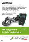
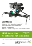
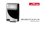
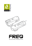
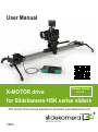
User Manual
Software version
rev 3.0
X-MOTOR drive
for Slidekamera HSK series sliders
PDF version of the manual available for download: www.slidekamera.com
MADE IN EUROPE
1/2015
Before you start your work with Slidekamera X-MOTOR drive for Slidekamera HSK series sliders we
strongly recommend to read the manual carrefully. Please note that using the drive in a manner
inconsistentwith the instructions, unauthorized repair attempts or any kind of modification of the drive
can cause damage the manufacturer is not responsible for.
In case of damage during transport you are required to submit:
R proof of purchase
R protective styrofoam inserts/ fillers included in the set in case of new product delivery
If you fail to comply with the abovementioned conditions, the manufacturer reserves
the right to refuse the complaint.
Photos of products may slightly differ from the actual product due to constant modifications
and improvements introduced by the manufacturer.
Slidekamera ®
High Engineering Technology CNC s.c.
Sebastian Pawelec Karol Mikulski
Glina 45
82-522 Sadlinki
Vat Identification Number: 581-188-33-32
Slidekamera Office
80-175 Gdańsk (Poland)
Ul. Kartuska 386
tel./fax (+48) 58 710 41 04
e-mail: [email protected] / [email protected]
www.slidekamera.pl / www.slidekamera.com
X-MOTOR drive for Slidekamera HSK series sliders
Table of contents
1. Elements of Slidekamera X-MOTOR drive .........................................................................................................3
2. Product description............................................................................................................................................4
2.1. HKN-ST controller...........................................................................................................................................4
2.2. X-GEAR..........................................................................................................................................................5
2.3. Heads set........................................................................................................................................................6
3. Specification......................................................................................................................................................6
4. Mounting Slidekamera X-MOTOR drive to HSK series slider...............................................................................7
4.1. Mounting drive heads......................................................................................................................................7
4.2 Connecting the drive unit with the cart...............................................................................................................8
4.3. X-GEAR mounting (motor+gear).....................................................................................................................8
5. How to operate the controller..............................................................................................................................9
5.1. Specifying startup parameters.........................................................................................................................9
5.1.1. AUTO (basic automatic calibration)...............................................................................................................9
5.1.2. MAN (manual calibration).............................................................................................................................9
5.1.3. FREE (no limits).........................................................................................................................................10
5.2. Main menu....................................................................................................................................................10
5.2.1. CONFIG menu...........................................................................................................................................10
5.2.1.1. Driving motor automatic calibration..........................................................................................................11
5.2.2. VIDEO........................................................................................................................................................11
5.2.2.1. Free Ride................................................................................................................................................12
5.2.2.2.Recording................................................................................................................................................13
5.2.2.3. Playback.................................................................................................................................................13
5.2.2.4. VideoLoop...............................................................................................................................................14
5.2.3.TIMELAPSE...............................................................................................................................................14
5.2.4. ANIMATION...............................................................................................................................................15
6. Maintenance and operation..............................................................................................................................17
7.Transport..........................................................................................................................................................17
8. Terms of warranty.............................................................................................................................................17
9. Shutter release cables for Slidekamera X-MOTOR drive...................................................................................18
10. Accessories for Slidekamera X-MOTOR drive................................................................................................19
X-MOTOR drive for Slidekamera HSK series sliders
1. Elements of Slidekamera X-MOTOR drive
Once you receive the shipment please make sure that all the elements of Slidekamera X-MOTOR drive are inside.
3
1
9
2
4
8
7
6
5
Set includes:
X-GEAR (driving motor with a worm gear and a housing equipped with a number of sockets) [1]
Set of drive heads (drive head that connects with a motor and a gear, and a driven head) connected with a toothed
belt with a carriage that connects the belt with a slider [2]
Controller that controls the movement of the slider cart [3 ]
Cable connecting the motor with the controller [4]
Shutter release cable to connect the motor with the photo camera [5]
Shutter release cable extender – 1.8m [6]
Four M6 x 90mm screws fixing the drive heads to the slider rail [7]
Hinge clamp with a washer [8]
AC Adapter [9]
A detailed list of shutter release cables and photo cameras
they support can be found on page 18 of this user manual.
3
X-MOTOR drive for Slidekamera HSK series sliders
2. Product description
Slidekamera X-MOTOR drive for HSK series sliders, is equipment specially designed for smooth shots in motion as
well as Timelapse photos. X-MOTOR drive consists of an intuitive controller and X-GEAR power unit. Simple and
functional menu of the controller provides excellent ergonomics of use. The controller allows to work in various
working programs: VIDEO, ANIMATION, TIMELAPSE. Front panel of the controller is equipped a joystick and two
knobs to adjust: SPEED and DAMPING. To eliminate any movement during shutter release, X-MOTOR set
includes a shutter release cable that is used in ANIMATION and TIMELAPSE working programs. X-GEAR power
unit allows for cartload of 7kg during vertical track and 20kg (see paragraph 3. Specification) during horizontal
track. HKN-ST controller is equipped with 1/4" mounting hole that allows to attach it to slider cart, for example, using
Slidekamera articulated arms: Magic Arm 8" or 11".
2.1. HKN-ST controller
Front panel of the controller is equipped a joystick and two knobs to adjust: SPEED and DAMPING. SPEED knob
allows to adjust speed range, whereas DAMPING knob regulates smooth acceleration and deceleration of
movement, ie. the user can adjust the time at which the drive reaches the desired speed or stops. RJ-45 cable
socket and power switch are located on the upper wall of the controller housing. Joystick, placed in the centre of the
front panel, enables user friendly programming, controlling and configuration. Simple and functional menu
provides the ergonomics of operation. HKN-ST controller is equipped with 1/4" mounting hole that allows to attach it
to slider cart, for example, using Slidekamera articulated arms: Magic Arm 8" or 11".
1
2
3
4
5
6
7
Power switch [1]
RJ-45 cable socket [2]
LCD display [3]
SPEED knob [4]
DAMPING knob [5]
Joystick [6]
1/4" mounting hole [7]
X-MOTOR drive for Slidekamera HSK series sliders
4
2.2. X-GEAR
X-GEAR power unit consists of a gear, motor and steering electronics. After connecting the power unit to the power
source, and attaching the cable connecting the controller [5] and the motor (cable should be connected to the
socket marked IN ) the device is ready. Turn on the controller and start the calibration.
8
7
9
4
3
6
5
Controller socket [1]
Socket for addidtional drives [2]
Power socket [3]
Shutter release cable socket [4]
Controller [5]
AC adapter [6]
Hinge clamp [7]
Drive head [8]
X-GEAR (motor+gear) [9]
7
3
4
2
1
Driving motor markings:
LINK
5
Indicates that controller cable is properly connected.
Rx
When orange light flashes slowly the user is informed that the driving motor is powered
but has not yet received any command from the controller.
When orange light starts flashing rapidly this indicates that the driving motor received a
command from the controller.
FAULT
Flashing light indicates existing error. Detailed explanations of erros codes can be
found in paragraph 5.2.1 of this user manual.
X-MOTOR drive for Slidekamera HSK series sliders
2.3. Heads set
A set of drive heads consists of two drive heads, one head per side, mounted to the slider with four M6x90 screws.
First drive head [1] is used for mounting X-GEAR [2] (motor + gear) using a hinge clamp [3]. Second drive head [4]
is equipped with 1/4 " and 3/8" holes with hardened inserts for attaching accessories.
1
3
2
4
3. Specification
Supply voltage:
10..18V DC
Current consumption:
Continuous horizontal track: max 1A @ 12V
Continuous vertical track with max. payload: 2,5A @ 12V
Operating time with battery 12V 7Ah (room
over 7h
temperature, horizontal track):
Cart speed:
maximum 50mm/s - in VIDEO program
minimum 100mm/999h - in TIMELAPSE program
Operating temperature range:
-10°C to 70°C
Shutter release cable (one to choose):
WS-1, WS-2, WS-3, WS-4, WS-5, WS-6, WS-7, WS-8, WS-9
cables used in ANIMATION, TIMELAPSE programs
Dimensions:
Width: 140mm
Length: 190mm
Height: 50mm (with joystic: 60mm)
Weight (controller, driving motor):
1720g
Slider cart payload:
Maximum payload for horizontal track: 20kg
Maximum payload for vertical track: 7kg
X-MOTOR drive for Slidekamera HSK series sliders
6
4. Mounting Slidekamera X-MOTOR drive to HSK series slider
4.1. Mounting drive heads
Instructions and explanations presented in following chapters contain set of guidelines recommended by the
manufacturer on how to properly mount X-MOTOR drive on Slidekamera HSK-5 sliders. Please note that
mounting and using the drive in a manner inconsistent with the instructions can cause damage the manufacturer is
not responsible for.
Place the drive heads [1] with the attached toothed belt [2] in parallel position to the slider. Pay attention so that the
drive head with a motor mounting axis is on the left side of the slider. The tooth belt must not be tangled.
1
1
2
Remove the sides of sliders [3].
3
Insert M6 x 90mm screws [4] through
the holes of the side feet and next
through the holes of the drive head.
Attach the screws to the slider.
3
4
Place the two parts of the belt
in a way so that they are outside
of the mounting ports of the slider rail
(mounting ports in the middleof the belt).
7
X-MOTOR drive for Slidekamera HSK series sliders
Insert M6 x 90mm screws [4] into the next side feet and then into the driven head [1]. Place the head to the slider rail
in a way so that the head is in contact with the lower edge of the rail. Straighten the head so that rail mounting holes
line up with the mounting holes of the head. Tighten the screws thus connecting the side feet and the head to the
slider rail.
1
4.2. Connecting the drive unit with the cart
Screw the hinge clamp [5] into the hole in the bottom of the slider brake [6]. Attach the carriage [7] (mounted to the
tooth belt) to the slider brake using the hinge clamp.
6
6
5
5
7
7
4.3. X-GEAR mounting (motor+gear)
Attach the motor with worm gear to the drive head mounted to the slider using the hinge clamp [1]. Place the clamp
on the gear in a way so that gear centring pins align with the drive head holes.
PLEASE NOTE: Pay attention so that the clutch teeth are properly positioned.
1
X-MOTOR drive for Slidekamera HSK series sliders
8
5. How to operate the controller
After you switch the power on the startup screen will appear on LCD for about 1,5s.
IMPORTANT!!!
Before the first use of the drive it is necessary to perform automatic
calibration of the driving motor. This step is necessary for the drive to function properly
and cannot be neglected. Automatic calibration is performed only before the first use,
it determines the range of movement for your HSK series slider.
5.1. Specifying startup parameters
After switching the power on it is necessary to determine the working mode of the drive. We differentiate three types
of modes: AUTO, MAN and FREE.
AUTO -basic automatic calibration. The dirve automatically moves to the reference point. Movement range
corresponds to the one specified during the automatic calibration.
MAN – the user determines the reference points (hence the movement range) by using the joystick and the
SPEED knob.
FREE – this mode does not require setting any movement range. Not recommended when working with HSK
series sliders.
5.1.1. AUTO (basic automatic calibration)
In case of AUTO working mode, after switching the power, a message will appear on LCD screen:
AUTO Referencing
<- or -> to run
Driver ready
press OK
Wówczas przy pomocy joysticka należy wskazać kierunek jazdy aby napęd automatycznie dojechał do punktu
skrajnego. Po ustaleniu punktu skrajnego na ekranie sterownika pojawi się komunikat o gotowości sterownika
do pracy. Po wciśnięciu OK (naciśnięcie joysticka) na ekranie pojawia się menu główne.
5.1.2. MAN (manual calibration)
n case of MAN working mode, the controller moves to the manual calibration. This mode allows to determine
the reference points anywhere on HSK series slider rail, not necessarily at the ends. This mode is recommended
if you need to determine a short range of motion for the cart.
When setting points of reference in MAN mode exercise extreme caution so that the cart does not hit
the side feet of your Slidekamera HSK series slider.
Message on the screen requires the user to determine points of reference. By moving the joystick right and left set
the reference points for the drive. Use SPEED knob to determine the speed of the cart, this will allow you to
deccelarate before the cart reaches second point of reference. Press the joystick to accept.
9
X-MOTOR drive for Slidekamera HSK series sliders
Set 1st RefPoint
<- -> & press OK
Set 2nd RefPoint
<- -> & press OK
As soon as the user sets the reference points, a message on LCD appears that the drive is ready for work. After
pressing OK (understood as pressing the joystick) the main menu appears on the screen.
Driver ready
press OK
5.1.3. FREE (no limits)
In case of FREE working mode, there are no limits as to the movement range. FREE Mode does not require setting
any reference points. The driver is immediately ready to work.
When working with the drive in FREE Mode exercise extreme caution.
Lack of reference points increases the risk of the cart hitting the side feet.
It may cause damage of the equipment.
5.2. Main menu
As soon as the startup parameters are determined the controller enters a main menu with working programs and
additional CONFIG menu. Navigate by moving joystick up and down. Sign "
" indicates selected choice.
Press the joystick to ented selected program. Main menu features four entries: „VIDEO”, „ANIMATION”,
„TIMELAPSE” and „CONFIG”.
5.2.1. Menu CONFIG
After entering [Info] there will be information about the voltage: Vin, and range of motion for the cart
determined during initial calibration: L.
ANIMATION
CONFIG
CONFIG menu has five entries "[Info]", "Power", "Backlight" , " [Calibration]" and
"<Back>". The list boxes in square brackets [] indicate functions generating own screen. In order to activate
them, press the joystick. At the end of each submenu there is "<Back>". Pressing the joystick in this field results
in returning to the main menu. The remaining fields of the submenu are the parameters, next is the value of the
parameter. To change the value move the joystick right or left.
Power- driving motor power: In case of X-GEAR it is 100% with not change possibility.
Back Light - adjusts the brightness of the LCD. By moving the joystick left or right you can set the
brightness within the range of: 10-100%
[Calibration] - driving motor automatic calibration described in point 5.2.1.1 of the manual
<Back> - return to main menu
X-MOTOR drive for Slidekamera HSK series sliders
10
UWAGA!
If the backlight of the LCD screen starts flashing and there wil be an orange
flashing light under FAULT marking on the right socket of the driving motor,
the user is informed about existing error. In such situation, immediately enter
CONFIG menu → [Info]. Information about the error should
appear in the upper right corner of the screen.
„V”: means that the battery voltage is too low. Replace
Vin=9.8V
V
the battery immediately in order to avoid to a sudden
L
1276.1mm
stop of the drive, which may result in damage
to the equipment.
„t”: (Thermal Warning) indicates temperature warning. Turn off the drive immediately so as not to overheat the
driving motor.
„T”: (Thermal Shutdown) indicates emergency drive shutdown due to overheating. You should
immediately turn off the drive and wait until FAULT light switches off.
5.2.1.1. Driving motor automatic calibration
Please note that automatic calibration is only possible when working with the slider. After selecting
[Calibration] from „CONFIG” menu a message appears on LCD:
CALIBRATION
in progress
CALIBRATION
<- or -> to run
Use the joystick to determine the direction of the movement so that the drive can automatically set the reference
points.
CALIBRATION
L 1276.1mm
After the automatic calibration is performed there will be
a message on the screen displaying the length of motion
range for the cart for your HSK series slider. After the power
is turned off the information is stored in the controller
so there is no need to repeat the procedure until you mount
the drive on a slider of a different length.
5.2.2. VIDEO
As you enter VIDEO program, a submenu will appear on the screen with different operating modes:
[Free Ride], [Recording], [Playback], [VideoLoop] ,<Back>.
VIDEO
TIMELAPSE
11
X-MOTOR drive for Slidekamera HSK series sliders
5.2.2.1. Free Ride
Free Ride mode allows the user to control the speed of the cart using joystick and adjusting knobs. SPEED knob
sets the maximum speed desired by the user. DAMPING knob is used to determine the time at which the drive
reaches the desired speed or stops, what allows to achieve very smooth acceleration and deceleration of the cart.
By moving the joystick right or left you can control the level of acceleration/deceleration of the cart. Pressing the
joystick causes the driving motor to stop immediately and the centroller returns to VIDEO menu.
1
FreeRide
1100.1
200
169
1.2
2
3
Current position of the cart, measured in mm [1]
Maximum speed of the cart set by the user [2]
Currently set speed [3]
Acceleration / deceleration time [4]
4
When you work in Free Ride mode you can change SPEED and DAMPING parameters at any time during
the movement. SPEED knob allows to set the speed value within the range of 2 -200mm/s. DAMPING knob allows
to set the acceleration/deceleration time within the range from 0.1s to 10s. Sample screen presented above
informs that the maximum speed of the cart is set on 200mm /s [2] , the currently set speed of the cart is 169mm/s
[3].The value is 1.2 [4] , means that the maximum speed will be achieved after 1.2 seconds.
Please note that depending on the chosen method of calibration the current position of the cart is measured and
presented on the screen in a different way. The table below illustrates and explains the messages on the controller.
The table refers to all modes and programs unless it is indicated otherwise in the manual.
Table showing the positioning of the cart for different calibration methods.
AUTO / MAN
FreeRide
1100.1
200
-169
1.2
FREE Mode
FreeRide
90
-40
-271.9
1.2
Selecting AUTO or MAN for a calibration method,
please note that the position of "0" means the left
extreme point of reference. The value grows as the cart
moves closer to the right extreme point of reference.
The direction of movement is indicated with currently
set speed value. If the currently set speed
is in the opposite direction it is marked with the sign "-".
Selecting FREE Mode the user does not determine
any reference points, therefore the position at which
the cart stands at that moment is marked as „0” (starting
point). From that starting point, any position to the left
is determined as a negative number whereas
any position to the right, as a positive number.
The direction of movement is indicated with currently
set speed value. If the currently set speed
is in the opposite direction it is marked with the sign "-".
X-MOTOR drive for Slidekamera HSK series sliders
12
5.2.2.2. Recording
Recording mode is designed to record the movements of cart in order to play it back later in Playback mode.
Movement control (SPEED and DAMPING) is exactly the same as in Free Ride mode, so the user can change
SPEED and DAMPING parameters at any time during the movement. In order to finish the recording and return to
the menu press the joystick. The controller can store 59 seconds of the recording. Recorded movement is stored in
the controller until the power supply is switched off.
Video Rec
148
69
2
3
1
1276.1
2.5
Current position of the cart, measured in mm [1]
Maximum speed of the cart set by the user [2]
Currently set speed [3]
Acceleration / deceleration time [4]
4
If length of the recorded movement exceeds 59 seconds,
a message on the screen will appear informing the user
that the controller memory is full.
To stop the recording before the end of 59 seconds, press
the joystick. In order to play back the recorded movement,
return to the main menu and enter Playback mode.
Video Rec 668.7
Memory Full
5.2.2.3. Playback
Playback mode plays back movements of the cart saved in Recording mode. Once you enter Playback mode the
screen displays information about the length of the recording or the lack of it.
[Recording]
> [Playback] 59s
Playback
0.0
No Records
When you select [Playback] there will be a message displayed on the screen: "Go Home?".
The controller requires the user decision whether the cart should return to the position where the recording
of movement started (-> Y) or whether to start playing back the movement from the current position of the cart
(N <-). Select the option by moving the joystick in the appropriate direction. You can return to VIDEO menu at any
time by pressing the joystick.
Playback
Go Home?
590.2
N<- ->Y
The controller displays information about the current
position of the cart [1] and the current/ overall time
of the recording [2]. As the recorded movement
stops press the joystick to return to VIDEO menu.
Playback
7267.4
press OK to Play
Playback 722.1
2
Time: 7/59s
13
1
Playback
58.4
press OK to exit
X-MOTOR drive for Slidekamera HSK series sliders
5.2.2.4. VideoLoop
During VideoLoop mode the cart moves from one reference point to the other without stop. It automatically turns
back and starts moving in the opposite direction once it reaches the end of the movement range. There is no need
for the user to determine the direction of the movement. The user can change SPEED and DAMPING parameters
at any time during the movement. SPEED knob allows to set the speed value of the cart [1]. DAMPING knob allows
to set the acceleration/deceleration time [2]. Pressing the joystick causes the driving motor to stop immediately and
the centroller returns to VIDEO menu.
VidLoop
36
1
856.6
3.1
In VideoLoop mode there is no "-" sign when
the cart moves in the opposite direction.
Current ly set speed of the cart [1]
Acceleration/deceleration time [2]
2
If you selected FREE Mode when setting startup parameters it is important to remember that the drive has no
reference points set. Consequently, it will move only in one direction and will not turn back. Use SPEED knob to
adjust the speed of the cart paying special attention so it does not hit side feet of the slider.
5.2.3. TIMELAPSE
TIMELAPSE program is designed for interval shots synchronized with the movement of the cart (Motion
Timelapse). Shutter release cable connected to the socket on driving motor enables to synchronize the drive with
the camera. After entering TIMELAPSE program the user has to set the parameters below:
Mode – Continuous / SDS working mode
Direction – cart movement direction: left/right
Interval – time at which the drive takes a shot (1-600s)
Expos. – duration time of the trigger signal (from 0.1 to 99.9 s)
Shots – number of photos to take during the track (from 10 to 30 thousand). Time of the track is
calculated automatically by the controller. It can be determined from the formula: Interval x
Shots
[Start] – TIMELAPSE program starts
<Back> – controller returns to main menu
In Continuous mode, the cart moves smoothly with a constant speed. In this case, there is no need to use the cable
release attached to the driving motor (especially for short exposure times). The release time can be successfully
set on the camera, or in the cable release with the interval function.
In SDS mode (Shot Drive Shot) the cart moves in steps between the points where you want to take photos.
The trigger signal, with a preset duration time (Expos.) is given to the next point before the cart moves. Shutter
release cable connected to the socket on driving motor enables to synchronize the drive with the camera.
The distance that the drive covers during the track is calculated from the place where the cart is currently located,
to the end of the range of movement in a set point direction (Direction).
Please note that it is important to select a proper direction of the movement in TIMELAPSE program.
If you choose movement direction as left and the cart will be located in the left reference point " 0",
the device will encounter resistance as it is the end of its movement range. Consequently, the drive will not move.
X-MOTOR drive for Slidekamera HSK series sliders
14
If specified startup parameters were: AUTO or MAN the
Set Step:
controller will calculate automatically length of step for SDS
< 10 >mm
mode and speed for Continuous mode. However, in FREE
mode, due to the fact that no reference points were defined,
after setting all parameters there would be an additional message on the controller screen asking the user to
manually determine the length of step: 1 – 999mm.
PLEASE NOTE: The controller will set the maximum length of step for the drive depending on the time that is has
for the movement (it is calculated from the formula: Interval-Exposure).
In case of Continuous mode, once you start TIMELAPSE mode (by selecting [Start]), use SPEED knob to set
the speed for the cart: 0.1 to 10 mm / s.
The sample screen presented below informs about the position of the cart on the slider rail [1]. There are 10 min left
until the end of the track [2]. The drive has already taken eight photos out of two hundred and fifty photos set by the
user [3]. The user can stop the program at any time by pressing the joystick for 2 seconds. When the drive has
taken all the photos and stops the program there will be a message on the screen: Timelaps end OK to
exit. Press the joystick to return to the main menu.
1
2
71.1
Shot:
0h10min
8/250
3
Current position of the cart [1]
Time remaining to the end of the track [2]
Number of currently taken shots /number of shots
to capture [3]
5.2.4. ANIMATION
ANIMATION allows to program track of the cart during which the drive take series of photos (the drive will trigger the
shutter release itself through a cable connected to the camera). After entering ANIMATION program set the
individual parameters:
Direction – direction in which the cart moves: right/ left
HomePos – home position (measured in mm). Position determined by the user from which the
drive should start its work. Home position can be determined in any place on the
rail (within the range of calibration)
Step – length of step (measured in mm)
Steps – number of steps. Controller calculates the maximum amount of steps basing on home
position (HomePos) and selected direction of movement.
Shots – number of shots to take after the cart stops
Delay – time of the delay. Time after the cart stops before the drive triggers the shutter (0-9s)
[Start] – ANIMATION program starts
<Back> – controller returns to main menu
When you select [Start] in ANIMATION program there will be a message displayed on the screen: "Go Home?".
The controller requires the user decision whether the cart should start the movement from determined HomePos
(-> Y) or whether to start the movement from the current position of the cart (N <-). Select the option by moving
the joystick in the appropriate direction. DirR on the screen indicates the selected direction of the movement,
in that particular example: right. You can return to the main menu at any time by pressing the joystick.
15
X-MOTOR drive for Slidekamera HSK series sliders
ANIM dirR
Go Home? N<- ->Y
Please note that it is important to select a proper directionof the movement in ANIMATION
program. If you choose movement direction as left and the cart will be located in the left
reference point " 0", the device will encounter resistance as it is the end of its movement range.
Consequently, the drive will not move.
After the user determines the desired starting position, information about current parameters will appear on the
LCD. In order to start, move the joystick in a direction you selected earlier. After the first step, move the joystick
again to initiate another steps. The user can freely move a step forward or backward (by moving the joystick right or
left) or skip a few steps forward or backward (by holding the joystick longer in a selected direction).
1
ANIM dirR
2/30 40.0
3
4
2
80.0
3/5
5
Selected movement direction [1]
Current position of the cart [2]
Current step/ number of programed steps [3]
Length of step [4]
Number of shots already taken/
number of all shots to take [5]
Sample screen presented above informs that the user selected right as movement direction [1]. If the user chose
left, there would be: dirL- on the screen. Current position of the cart is 80mm [2] from the left reference point in
AUTO or MAN mode, or starting point in FREE Mode. Length of step set by the user is 40mm [4]. The drive
currently performs second step out if thirty steps set [3]. The drive has already taken three shots out of five shots
set [5].The user can stop the program at any time by pressing the joystick. When the drive has taken all the photos
and stops the program there will be a message on the screen with the current position of the cart. Press the joystick
to return to the main menu.
ANIM dirR 327.0
press OK. to exit
X-MOTOR drive for Slidekamera HSK series sliders
16
6. Maintenance and operation
Maintenance of Slidekamera X-MOTOR drive reduces to keeping the drive clean. Use professional maintenance
products for this type of equipment, such as Dry Lube with Teflon or antistatic cloth. Elements of the drive do not
require any lubrication.
Any changes in design and repairs are made only and exclusively by the manufacturer.
Failure to comply with the recommended guidelines outlined in this manual
will result in loss of warranty.
7. Transport
Slidekamera X-MOTOR drive must be transported in a transport box that provides a proper protection
of the equipment against any damage. The manufacturer recommends using Slidekamera cover with foam insert
for X-SLIDER. Slidekamera transport covers are designed for comfortable and secure transport of your photo and
video equipment.
8. Gwarancja
All Slidekamera products are covered manufacturer's warranty for a period of 12 months from the date of sale.
Warranty covers any design faults or of the material of the product which resulted in the product malfunctioning.
The warranty covers the repair, or, if the repair proves impossible, replacement of the product with a new one.
Hovewer, the cost of repair of the product cannot overrun the catalogue value of the product. The warranty does not
cover damage and / or product defects resulting from the improper usage, as well as not following product
maintenance specifications.
The warranty excludes:
R unauthorized attempts to repair or modify
R mechanical damage caused during transport and operation of such features as scratches, dents, pits,
dirt, etc ...
R flooding, moisture
To obtain warranty service the purchaser should deliver the damaged product together with a proof of purchase and
proof of payment (invoice, cash register receipt). The product will be accepted for warranty service on condition that
it is delivered with correctly filled in complaint form and properly protected during transport. You can download the
complaint from: www.slidekamera.pl / www.slidekamera.com.
After the warranty period is exceeded any spare parts can be purchased directly from the manufacturer or in any
selected points of sale.
PLEASE NOTE: Any package sent at the expense of HET-CNC s.c., 80-175 Gdańsk, Ul. Kartuska 386 will not be
received
17
X-MOTOR drive for Slidekamera HSK series sliders
9. Shutter release cables for Slidekamera X-MOTOR drive
Supported cameras
Type:
WS-1
Canon: EOS 10D, EOS 1D, EOS 1D C, EOS 1D mk II, EOS 1D mk II N, EOS 1D mk III, EOS 1D mk IV,
EOS 1D X, EOS 1Ds, EOS 1Ds mk2, EOS 1Ds mk3, EOS 20D, EOS 20Da, EOS 30D, EOS 40D, EOS
50D, EOS 5D, EOS 5D mk II, EOS 5D mk III, EOS 6D, EOS 7D, EOS D30, EOS D60
Kodak: DSC-530 (i inne)
WS-2
Canon: Digital Rebel, EOS 1000D, EOS 100D, EOS 1100D, EOS 300D, EOS 350D, EOS 400D, EOS
450D, EOS 500D, EOS 550D, EOS 600D, EOS 60D, EOS 60Da, EOS 650D, EOS 700D, EOS 70D,
Kiss Digital, Kiss F Digital, Kiss N, Kiss X2, Kiss X3, Kiss X4, Kiss X5, Kiss X50, Kiss X6, PowerShot G1
X, PowerShot G10, PowerShot G11, PowerShot G12, PowerShot G15, PowerShot SX50 HS, Rebel
SL1, Rebel T1i, Rebel T2i, Rebel T3, Rebel T3i, Rebel T4i, Rebel T5i, Rebel XS, Rebel XSi, Rebel XT,
Rebel Xti,
Contax: 645, N, N Digital, N1, NX
FujiFilm: X-E1
Hasselblad: H, H3D, H4D-200MS, H4D-31, H4D-40, H4D-50, H4D-50MS, H4D-60,
Pentax: 645D, ist D, ist DL, ist DL2, ist DS, ist DS2, K-30, K-5, K-5 II, K-5 IIs, K-50, K-500, K-7, K-m,
K10 Grand Prix, K100D, K100D Super, K10D, K1 10D, K200D, K20D, MZ-6, MZ-L, ZX-L,
Samsung: GX-1L, GX-1S, GX-20, NX-10, NX-100, NX-11, NX-5
Sigma: SD1, SD1 Merrill, SD15 (i inne)
WS-3
FujiFilm: S3 Pro, S5 Pro
Kodak: DCS Pro 14n
Nikon: D1, D1H, D1X, D2, D200, D2H, D2HS, D2X, D2XS, D3, D300, D300S, D3s, D3X, D4, D700,
D800, D800 E, D1, D100(with MB-D100 battery grip), D1H, D1X, D2, D200, D2H, D2HS, D2X, D2XS,
D3, D300, D300S, D3s, D3X, D4, D4s, D700, D800, D800 E i D810 (i inne)
WS-4
Nikon: D3100, D3200, D5000, D5100, D5200, D60, D7000, D7100, D90, D750, (i inne)
WS-5
Nikon: D70S, Nikon D80 (i inne)
WS-6
Leica: DigiLux 2, DigiLux 3, V Lux 1, V Lux 2, V Lux 3
Panasonic: FT2, FZ100, FZ15, FZ150, FZ20,FZ200, FZ30, FZ50, G1, G10, G2, G3, G5, GF1, GH1,
GH2, GH3, GX1, L1, L10, LC1, TS2, GH4 (i inne)
WS-7
Hassleblad HV
Minolta DiMAGE: 5, 7, 7Hi, 7i, A1, A2, A200
Minolta Dynax: 3, 4, 5000, 500si, 505si, 5D, 7, 7000, 7D, 9, 9000, Sweets
Minolta Maxxum: 3, 4, 5000, 500si, 505si, 5D, 600si, 7, 7000, 700si, 7D, 807si, 9, 9000
Sony: A100, A200, A300, A33, A35, A350, A37, A400, A450, A500, A55, A550, A550V, A560, A57,
A580, A65, A65V, A700, A77, A77V, A850, A900, A99
WS-8
Olympus: SP-590 SP-570 SP-550 E-520 E-P3
WS-9
Sony Alpha A7, A7R, A7S, A58, A3000, A5000, A5100, A6000
Sony RX10, RX100 II, RX100 III, HX300, HX50V, HX60V, NEX-3NL
Photo cameras with no shutter release socket: Nikon D3000
X-MOTOR drive for Slidekamera HSK series sliders
18
10. Accessories for Slidekamera X-MOTOR drive
Power supply:
Slidekamera AF-7 power pack [1] with AF-7-K1 power lead [2]
2
1
Slide Kamera HSK series slider:
HSK-5/ HSK-6 slider STANDARD [3]
HSK-5 / HSK-6 slider PRO [4]
4
3
Depending on the model sliders are equipped with a different
type of side feet: STANDARD or PRO.
Available lengths of HSK-5 slider: 1000,1500, 2000mm.
Transport:
Slidekamera cover with foam insert for X-SLIDER 1300-2300mm [5]
PSK transportt cover [6]
5
19
6
X-MOTOR drive for Slidekamera HSK series sliders
Additional accessories:
Slidekamera Magic Arm 8" [1]
Slidekamera Magic Arm 11" [2]
1
2
Shutter release cables:
WS-1 [1]
WS-2 [2]
WS-3 [3]
WS-4 [4]
WS-5 [5]
WS-6 [6]
WS-7 [7]
WS-8 [8]
WS-9 [9]
1
6
7
2
3
8
9
4
5
X-MOTOR drive for Slidekamera HSK series sliders
20