1
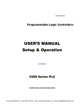
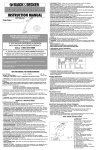
U4D100 4K Ultra HD 4 wire to 1080p Down Converter Installation and Operation manual TECHNICAL MANUAL U4D100 Hercules 28 NL-5126 RK Gilze The Netherlands Phone: +31 161 850 450 Fax: +31 161 850 499 E-mail: [email protected] Web: www.axon.tv WARNING: TO REDUCE THE RISK OF FIRE OR ELECTRICAL SHOCK, DO NOT EXPOSE THIS APPLIANCE TO RAIN OR MOISTURE ● ALWAYS disconnect your entire system from the AC mains before cleaning any component. The product frame (SFR18 or SFR04) must be terminated with three-conductor AC mains power cord that includes an earth ground connection. To prevent shock hazard, all three connections must always be used. ● NEVER use flammable or combustible chemicals for cleaning components. ● NEVER operate this product if any cover is removed. ● NEVER wet the inside of this product with any liquid. ● NEVER pour or spill liquids directly onto this unit. ● NEVER block airflow through ventilation slots. ● NEVER bypass any fuse. ● NEVER replace any fuse with a value or type other than those specified. ● NEVER attempt to repair this product. If a problem occurs, contact your local Axon distributor. ● NEVER expose this product to extremely high or low temperatures. ● NEVER operate this product in an explosive atmosphere. Warranty: Axon warrants their products according to the warranty policy as described in the general terms. That means that Axon Digital Design BV can only warrant the products as long as the serial numbers are not removed. Copyright © 2001 – 2014 AXON Digital Design B.V. Date created: 24-06-2014 Date last revised: 24-06-2014 Axon, the Axon logo and Synapse are trademarks of Axon Digital Design B.V. This product complies with the requirements of the product family standards for audio, video, audio-visual entertainment lighting control apparatus for professional use as mentioned below. EN60950 EN55103-1: 1996 EN55103-2: 1996 Axon Digital Design GDR216 Tested To Comply With FCC Standards Safety Emission Immunity This device complies with part 15 of the FCC Rules Operation is subject to the following two conditions: (1) This device may cause harmful interference, and (2) This device must accept any interference received, including interference that may cause undesired operation. FOR HOME OR OFFICE USE 3 Table of Contents Introduction to Synapse 6 An Introduction to Synapse Local Control Panel Remote Control Capabilities 6 6 6 Unpacking and Placement 7 Unpacking Placing the card 7 7 A Quick Start 8 When Powering-up Changing settings and parameters Front Panel Control Example of changing parameters using front panel control Axon Cortex Software Menu Structure Example The U4D100 Card Introduction Features Applications Block schematic 8 8 8 9 10 10 11 11 11 11 12 Settings Menu 13 Introduction IO_Prst_Act IO_Prst_Edit #Out-Frmt #Out_Map #Mode #H-Sharpness #H_delay #V_delay #F_delay #OSD-Style Lock-Mode Ref-Type Delay-Status IP_Conf0 mIP0 mNM0 mGW0 NetwPrefix0 13 13 13 13 13 13 13 14 14 14 14 14 14 14 15 15 15 15 15 Status Menu 16 Introduction sInp1 IO-Delay Ref IP_Addr0 Mac0 IP0 NM0 GW0 16 16 16 16 16 16 16 16 16 Events Menu 17 Introduction What is the Goal of an event? Events Announcements Ref-Status What information is available in an event? The Message String The Tag Defining Tags The Priority The Address LED Indication 17 17 17 17 17 17 17 17 18 18 18 19 4 Error LED Input_1 LED Reference LED Connection LED Error LED 19 19 19 19 19 9 Block Schematic 20 Connector Panels 21 5 1 Introduction to Synapse An Introduction to Synapse is a modular system designed for the broadcast industry. Synapse High density, intuitive operation and high quality processing are key features of this system. Synapse offers a full range of converters and processing modules. Please visit the AXON Digital Design Website at www.axon.tv to obtain the latest information on our new products and updates. Local Control The local control panel gives access to all adjustable parameters and Panel provides status information for any of the cards in the Synapse frame, including the Synapse rack controller. The local control panel is also used to back-up and restore card settings. Please refer to the RRC18, RRC10, RRC04, RRS18 and RRS04 manuals for a detailed description of the local control panel, the way to set-up remote control over IP and for frame related settings and status information. Remote Control The remote control options are explained in the rack controller Capabilities manual. The method of connection to a computer using Ethernet is also described in the ERC/ERS/RRC/RRS manual. ! CHECK-OUT: “AXON CORTEX” SOFTWARE WILL INCREASE SYSTEM FLEXIBILITY OF ONE OR MORE SYNAPSE FRAMES Although not required to use Cortex with a Synapse frame, you are strongly advised to use a remote personal computer or laptop PC with Axon Cortex installed, as this increases the ease of use and understanding of the modules. 6 2 Unpacking and Placement Unpacking The Axon Synapse card must be unpacked in an anti-static environment. Care must be taken NOT to touch components on the card – always handle the card carefully by the edges. The card must be stored and shipped in anti-static packaging. Ensuring that these precautions are followed will prevent premature failure from components mounted on the board. Placing the card The Synapse card can be placed vertically in an SFR18 frame or horizontally in an SFR04 and SFR08 frame. Locate the two guide slots to be used, slide in the mounted circuit board, and push it firmly to locate the connectors. Correct insertion of card is essential as a card that is not located properly may show valid indicators, but does not function correctly. NOTE: On power up all LED’s will light for a few seconds, this is the time it takes to initialise the card. 7 3 A Quick Start When Powering- On powering up the Synapse frame, the card set will use basic data up and default initialisation settings. All LED’s will light during this process. After initialisation, several LED’s will remain lit – the exact number and configuration is dependent upon the number of inputs connected and the status of the inputs. Changing settings The front panel controls or the Axon Cortex can be used to change and parameters settings. An overview of the settings can be found in chapter 5, 6 and 7 of this manual. Front Panel Front Panel Display and Cursor Control [No Alarms] Settings are displayed and changed as follows; Use the cursor ‘arrows’ on the front panel to select the menu and parameter to be displayed and/or changed. Press ► Press ◄ Press ▲ Press ▼ To go forward through the menu structure. To go back through the menu structure. To move up within a menu or increase the value of a parameter. To move down through a menu or decrease the value of a parameter. NOTE: Whilst editing a setting, pressing ► twice will reset the value to its default. 8 Example of With the display as shown below changing parameters using front panel control RRC18 [Select Card] >S01=SFS10 Pressing the ► selects the SFS10 in frame slot 01. The display changes to indicate that the SFS10 has been selected. In this example the Settings menu item is indicated. SFS10 [Select Menu] >Settings Pressing the ► selects the menu item shown, in this example Settings. (Pressing ▲ or ▼ will change to a different menu eg Status, Events). The display changes to indicate that the SFS10 Settings menu item SDI-Format has been selected and shows that it current setting is Auto. SFS10 [Settings] >SDI-Format=Auto Pressing the ► selects the settings item shown, in this example SDI-Format. (Pressing ▲ or ▼ will change to a different setting, eg Mode, HDelay). The display changes to indicate that the SFS10 Edit Setting menu item SDI-Format has been selected. SFS10 Edit Setting] SDI-Format>Auto To edit the setting of the menu item press ▲ or ▼. All menu items can be monitored and/or changed in this way. Changing a setting has an immediate effect. 9 Axon Cortex Axon Cortex can be used to change the settings of Synapse modules Software from a PC, either locally or remotely. The software enables communication based on TCP/IP between the Setup PC and Synapse frames/modules. Each Synapse frame is addressed through its rack controller’s unique IP address, giving access to each module, its menus and adjustment items. Axon Cortex has access to data contained within the Synapse module and displays it on a GUI. The software has an intuitive structure following that of the module that it is controlling. For operation of Axon Cortex, please refer to the Cortex help files. Menu Structure Example Slot ▲ ▲ S02 ▲ S01 ▼ S00 Module SFS10 RRC18 Item Identity ▲ ► Settings ▼ Status ▼ Events Parameter Setting ► Standard_dig ► Auto ▼ Mode ▼ Ref-Input ▼ H-Delay ▼ ▼ ▼ 625 ▼ 525 NOTE: Further information about Front Panel Control and Synapse Cortex can be obtained from the RRC and RRS operational manuals and the Cortex help files. 10 4 The U4D100 Card Introduction The U4D100 is a 4K (3840x2180), 4 wire, to 1080p down-converter. The low latency unit combines and filters the four quadrants into a 1080p (1920x1080) signal. Features Applications Four wire 1080p 50 or 59.94 input (level B compliant) One 1080p signal on 4 outputs Low Latency (1 1080p Frame 20ms @ 50Hz, 16.7ms @ 59.94 Hz) 4K 4 wire (3840 x 2160) Compatible with the following formats (auto selecting) 1080p/59.94 1080p/50 Transparent for 16 channels of embedded audio The BPH17 can optionally be fitted with up to two fiber I/O modules (inputs or outputs) Full control and status monitoring through the front panel of the SFR04/SFR08/SFR18 frame and the Ethernet port (ACP) Down conversion for 4K production sets 11 Block schematic U4D100 EQ SCALER EQ SCALER 4 QUADRANT COMBINER 4 EQUAL OUTPUTS EQ SCALER EQ SCALER 3Gb/s OUT 3 LOW LATENCY 4K (3840X2160) 4 WIRE TO 1080P DOWN CONVERTER µP [LINUX] RACK CONTROLLER INTERNAL SYNAPSE BUS 12 5 Settings Menu Introduction The settings menu displays the current state of each setting and allows you to change or adjust it. Settings can be changed using the front panel of the Synapse frame (SFR18, SFR08 or SFR04) or with Cortex. Please refer to chapter 3 for information on the Synapse front panel control and Cortex. Note: All items preceded with a #-sign are part of the presets. SYSTEM SETTINGS IO_Prst_Act With this item you can manually change the currently active IO settings. Can be any preset between 1 and 8. By default it is set to 1. Menu settings that are preceded with a ‘# ‘-prefix are part of the preset, except for the anaglyph mode presets. IO_Prst_Edit Here you can select which of the 8 selectable IO settings presets you want to edit. Changing this will not change the active preset, unless the currently active preset is the same you are going to edit. Menu settings that are preceded with a ‘# ‘-prefix are part of the preset, except for the anaglyph mode presets. #Out-Frmt With Out-Frmt you can set what the output format is. Possible settings are: 1080p60 1080p50 Auto #Out_Map The setting item Out_Map determines if the output signal is mapped according Level-A or Level-B. on input A will be reclocked by the GDR216. The settings are: ■ Auto: Ouput mapping follows input map detection. ■ Level-A: Fixed level-A ■ Level-B: Fixed level-B The default setting is Auto. #Mode The setting Mode determines if the output signal is down converted or the input is passed to the output. Settings are Pass (Default) Down #H-Sharpness With H-Sharpness you can select how much detail enhancement you want to add. Ranges from 0% to 100%. The Default is 0%. 13 #H_delay The H-Delay setting allows adjustment of the Horizontal phase of the output signal with respect to the selected reference input. The H-Delay setting gives a delay in addition to the reference timing. For example: if the H-Delay is set to 10 pixels, the output signal will be delayed by reference timing + 10 pixels. The signal is delayed (advanced) with respect to the phase of the reference signal. The available range is from 0 to a maximum of 2639 pixels (depends on I/O format). The default setting is 0px. #V_delay V-Delay setting allows adjustment of the vertical phase of the output signal with respect to the selected reference input. The V-Delay setting gives a delay in addition to the reference timing. For example: if the V-Delay is set to 10 TV HD lines, the output signal will be delayed by reference timing + 10 TV HD lines. The signal is delayed (advanced) with respect to the phase of the reference signal. The available range is from 0 to a maximum of 1124 lines. The default setting is 0ln. #F_delay F-Delay sets the amount of delayed Frames. The available range is from 0 to 7 frames. Default is 0F. #OSD-Style Selects the style of the On Screen Display text. The following are possible: ■ Off. ■ Transp: Enables the text in transparent mode. ■ Masked: Enables the text in masked mode. ■ Blink-Transp: Blinkes the text in transparent mode. ■ Blink-Masked: Blinkes the text in masked mode. Lock-Mode Lock-Mode determines whether the card is locked to his input (input 1), to the reference (Ref1 or Ref2) or freerun (not locked). By default it is set to Ref1. Ref-Type Sets the type of incoming reference. Can be either Bi-Level or TriLevel. Default is Bi-Level. Delay-Status It is possible to display the processing time of the card in the status menu. This setting allows you to switch this function ON or OFF. Due to bus traffic the default setting is OFF. 14 NETWORK IP_Conf0 With this setting you can let the card obtain an IP address automatically via DHCP, or appoint a manual set IP address. By default this setting is set to Manual. mIP0 When IP_Conf0 is set to manual, you can type in the preferred IP address here. By default it is set to 172.16.1.2 mNM0 With IP_Conf0 set to manual, with this setting you can set a Netmask. Default is 255.255.0.0 mGW0 With IP_Conf0 set to manual, this setting let you set a Standard Gateway. Default is set to 172.16.0.1 NetwPrefix0 Here you can set the proper network prefix if required. 15 6 Status Menu Introduction The status menu indicates the current status of each item listed below. There are no defaults for status indicators. Status depends of input signals being present or not. sInp1 This status item indicates the presence and format of a valid signal in input 1. This is displayed as: 1080P60 1080p50 NA IO-Delay Displays the total delay in ms between the Input and Output. Value between 20ms and 160ms. Ref Displays whether a correct reference is found (Present) or not (NA) NET STATUS IP_Addr0 This item displays the status of the IP address. It can be manual, DHCP asking, DHCP Leased or DHCP Infin. Mac0 This item displays the MAC address of the card. IP0 This item displays the current IP address of the card. NM0 This item displays the current Netmask of the card. GW0 This item displays the current Standard Gateway of the card. 16 7 Events Menu Introduction An event is a special message that is generated on the card asynchronously. This means that it is not the response to a request to the card, but a spontaneous message. What is the Goal of The goal of events is to inform the environment about a changing an event? condition on the card. A message may be broadcast to mark the change in status. The message is volatile and cannot be retrieved from the system after it has been broadcast. There are several means by which the message can be filtered. Events The events reported by the U4U100 are as follows; Announcements Announcements is not an event. This item is only used for switching the announcement of status changes on/off. 0=off, other =on Ref-Status Reference status can be selected between 0 .. 255. 0= no event, 1..255 is the priority setting. Default is Off. What information is The message consists of the following items; available in an 1) A message string to show what has happened in text, for example: event? “INP_LOSS”, “REF_LOSS”, “INP_RETURN”. 2) A tag that also shows what happens, but with a predefined number: e.g. 1 (= loss of input), 2 (= loss of reference), 129(= 1+128 = return of input). For a list of these predefined tags see the table on the next page. 3) A priority that marks the importance of an event. This value is defined by the user and can have any value between 1 and 255, or 0 when disabled. 4) A slot number of the source of this event. The Message String The message string is defined in the card and is therefore fixed. It may be used in controlling software like Synapse Set-up to show the event. The Tag The tag is also defined in the card. The tag has a fixed meaning. When controlling or monitoring software should make decisions based on events, it is easier to use the tag instead of interpreting a string. The first implementation is the tag controlled switch in the GPI16. In cases where the event marks a change to fault status (e.g. 1 for Loss of Input) the complement is marked by the tag increased by 128 (80hex) (e.g. 129 (81hex) for Return of Input). 17 Defining Tags The tags defined for the card are: Event Menu Item Announcements Tag Tag 0 or NA 0 or NA Input_A 01hex =INP_LOST 81hex =INP_RETURN Lock-status_A 11 hex =PLL_LOCKED 91 hex =PLL_UNLOCKED Input_B 12 hex =INP_LOST 92 hex =INP_RETURN Lock-status_B 51 hex =PLL_LOCKED d1 hex =PLL_UNLOCKED Active_Out_A 19 hex =IN_B_->_OUT_A 99 hex =IN_A_->_OUT_A Active_Out_B 1a hex =IN_A_->_OUT_B 9a hex =IN_B_->_OUT_B Description Announcing of report and control values SDI input A lost or returned PLL input A locked or unlock SDI input B lost or returned PLL input B locked or unlock Active output A is In_B or In_A Active output B is In_A or In_B The Priority The priority is a user-defined value. The higher the priority of the alarm, the higher this value. Setting the priority to Zero disables the announcement of this alarm. Alarms with priorities equal or higher than the Error Threshold setting of the RRC will cause the error LED on the Synapse rack front panel to light. The Address Together with the message string or the tag, the slot number or address of the card is relevant to be able to assign the event to a certain card. 18 8 LED Indication Error LED The error LED indicates an error if the internal logic of the card is not configured correctly or has a hardware failure. Input_1 LED This LED indicated the presence of a valid SDI video signal on input 1. Reference LED Indicated the presence of a valid reference signal on the selected reference input connector (ref-1 or ref-2). Connection LED This LED illuminates after the card has initialized. The LED lights for 0.5 seconds every time a connection is made to the card. Error LED The error LED indicates an error if the internal logic of the card is not configured correctly or has a hardware failure. 19 9 Block Schematic U4D100 EQ SCALER EQ SCALER 4 QUADRANT COMBINER 4 EQUAL OUTPUTS EQ SCALER EQ SCALER 3Gb/s OUT 3 LOW LATENCY 4K (3840X2160) 4 WIRE TO 1080P DOWN CONVERTER µP [LINUX] RACK CONTROLLER INTERNAL SYNAPSE BUS 20 10 Connector Panels The U4D100 can be used with the BPH17 BPH17 3Gb/s INPUT 1 (LEFT TOP) 3Gb/s INPUT 2 (RIGHT TOP) 3Gb/s PROCESSED OUT 1 (OPTIONAL FIBER OUT) 3Gb/s PROCESSED OUT 2 (OPTIONAL FIBER OUT) GPI 3Gb/s PROCESSED OUT 3 3Gb/s PROCESSED OUT 4 3Gb/s INPUT 3 (LEFT BOTTOM) 3Gb/s INPUT 4 (RIGHT BOTTOM) 21