1
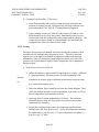
APICAL INDUSTRIES, INCORPORATED
2608 Temple Heights Drive
Oceanside, California 92056
ICA350-2
Rev. N/C
97Oct02
INSTRUCTIONS FOR CONTINUED AIRWORTHINESS
FOR
UTILITY HELICOPTER FLOAT ASSEMBLIES
EUROCOPTER HELICOPTER AS-350
FLOAT ASSEMBLY - P/N 20331-101 AND 20331-102
Page 1
APICAL INDUSTRIES, INCORPORATED
2608 Temple Heights Drive
Oceanside, California 92056
ICA350-2
Rev. N/C
97Oct02
LOG OF ACCEPTED REVISIONS
Apical Industries, Incorporated’s Instructions for Continued Airworthiness (ICA) for the
Eurocopter AS-350 rotorcraft except for the Airworthiness Limitations Section (ALS) were
reviewed by the Fort Worth Aircraft Evaluation Group (FTW AEG) and found to contain the
applicable requirements specified in Appendix A to Federal Aviation Regulations Part 27, as
appropriate, and do not contain any incorrect terminology or incorrect references. These ICA
were found to contain a Cover Page, Log of Accepted Revisions, Revision Control Procedure
and Record of Revisions, a List of Effective Pages, and a Table of Contents. No determination
as to correct spelling, proper grammar, or accuracy of the information was made by the FTW
AEG. For ICA having a required Airworthiness Limitations Section (ALS), the ICA will be
acceptable when this page has been signed and dated by the FTW AEG and the ALS is approved
by the Aircraft Certification Service. When the ICA do not require an approved ALS, the ICA
will be acceptable when this page has been signed and dated by the FTW AEG.
Revision
Number
Revision
Date
FAA Acceptance
Signature
N/C
Page 2
Acceptance
Date
Accepting
AEG Office
APICAL INDUSTRIES, INCORPORATED
2608 Temple Heights Drive
Oceanside, California 92056
ICA350-2
Rev. N/C
97Oct02
RECORD OF REVISIONS
Revision
Number
N/C
Issue
Date
Date
Inserted
By
Revision
Number
Page 3
Issue
Date
Date
Inserted
By
APICAL INDUSTRIES, INCORPORATED
2608 Temple Heights Drive
Oceanside, California 92056
ICA350-2
Rev. N/C
97Oct02
DETAILS OF REVISIONS
REV. DATE
N/C
97Oct02
PAGE DESCRIPTION
All
Initial Release
APPROVED
Committee
Page 4
APICAL INDUSTRIES, INCORPORATED
2608 Temple Heights Drive
Oceanside, California 92056
ICA350-2
Rev. N/C
97Oct02
RECORD OF SERVICE BULLETINS (S/B’S)
S/B NO.
DATE
DESCRIPTION
Page 5
APICAL INDUSTRIES, INCORPORATED
2608 Temple Heights Drive
Oceanside, California 92056
ICA350-2
Rev. N/C
97Oct02
LIST OF EFFECTIVE PAGES
LIST OF REVISIONS
Revision N/C
97Oct02
LIST OF EFFECTIVE PAGES
Title
Page Revision No.
Cover
Log of Accepted Revisions
Record of Revisions
Details of Revisions
Record of Service Bulletins
List of Effective Pages
Table of Contents
List of Tables and Figures
Section 1.0
Introduction
Section 4.0
Airworthiness Limitations
Section 5.0 Inspection Requirements and Overhaul Schedule
Section 9.0 Towing
Section 11.0 Placards
Section 25.0 Float Removal, Cleaning, Testing, Field Repairs
and Reinstalling
Attachment 1 Customer Feedback
1
2
3
4
5
6
7
Page 6
8
9-11
12
13
14
15
N/C
N/C
N/C
N/C
N/C
N/C
N/C
N/C
N/C
N/C
N/C
N/C
N/C
16-31
32
N/C
N/C
APICAL INDUSTRIES, INCORPORATED
2608 Temple Heights Drive
Oceanside, California 92056
ICA350-2
Rev. N/C
97Oct02
TABLE OF CONTENTS
Identification
Title
Section 1.0
Introduction
1.1
Scope
1.2
Purpose
1.3
Revision Control Procedure
1.4
Service Difficulty Reporting
1.5
Applicability
1.6
Abbreviations
1.7
Precautions
1.8
Units of Measurement
1.9
Distribution
1.10 Description of the System and Installation
9
9
9
9
9
9
10
10
10
10
11
Section 4.0
Airworthiness Limitations Section
12
Section 5.0
13
Inspection Requirements and Overhaul Schedule
5.1
5.2
Page
Inspection Requirements
Component Overhaul Schedule
13
13
Section 9.0
Towing
14
Section 11.0
Placards
11.1
11.2
11.3
15
15
15
15
Section 25.0
Placard Information
Location
Application
Float Removal, Cleaning, Testing, Field Repairs and Reinstalling
25.1 Floats
25.1.1 Float Removal
25.1.2 Table II
25.1.3 Table III
25.1.4 Cleaning
25.1.5 Testing
16
16
16
16
17
17
18
25.1.6 Field Repairs
25.1.7 Reinstalling Floats
20
28
29
25.1.8 Completion of Installation
25.2 Illustrated Parts List
Page 7
30
APICAL INDUSTRIES, INCORPORATED
2608 Temple Heights Drive
Oceanside, California 92056
ICA350-2
Rev. N/C
97Oct02
LIST OF TABLES
Table Number
Description
Page
I
II
16
III
IV
V
VI
VII
VIII
28
Float Characteristics
Consumable Cleaning Materials Required
11
Visual Check of Assemblies and Components
Testing Equipment/Materials Required
Helicopter Float Repair Kit Items
Trouble Shooting-Float Will Not Maintain Operating Pressure
Special Tools
Repair Materials Required
17
20
21
27
27
LIST OF FIGURES
Figure Number
Description
Page
A
B
27
C
D
E
Placard 20377-1
Valve Removal and Replacement - PRV and Topping Valve
15
Float Attaching Hardware
Utility Float
Float Attaching Hardware
29
30
31
Page 8
APICAL INDUSTRIES, INCORPORATED
2608 Temple Heights Drive
Oceanside, California 92056
1.0
1.1
ICA350-2
Rev. N/C
97Oct02
INTRODUCTION
Scope
This manual provides description, operation, disassembly, assembly, repair and testing
instructions and an Illustrated Parts List for the 20331 Series Utility Helicopter Floats.
The equipment is manufactured by Apical Industries, Incorporated, Oceanside,
California.
1.2
Purpose
The purpose of this manual is to maintain the Eurocopter AS-350 Utility Helicopter Float
System in peak operating efficiency with the greatest service life.
1.3
Revision Control Procedure
All revisions to this document shall be controlled by the Apical Engineering Change
Notice procedure. Each revision will be indicated with a vertical change bar. Each
revised page shall display the next revision letter and all pages will be summarized on
page 6, “List of Effective Pages.”
The final sign off shall be by the Fort Worth AEG Office on page 2, “Log of Accepted
Revisions.”
1.4
Service Difficulty Reporting
Service Difficulty Reporting shall utilize the form included as Attachment 1.
1.5
Applicability
This manual shall be used to maintain the utility floats for the Eurocopter AS-350.
Page 9
APICAL INDUSTRIES, INCORPORATED
2608 Temple Heights Drive
Oceanside, California 92056
ICA350-2
Rev. N/C
97Oct02
1.6
Abbreviations
psi
= pounds per square inch
psig = pounds per square inch gauge
ft. lbs. = foot pounds
in. lbs. = inch pounds
ºF
= degrees Fahrenheit
ºC
= degrees Celsius
Hg
= mercury
PRV = pressure relief valve
P/N = part number
F/N = find number
LH
= left hand
RH
= right hand
1.7
Precautions
The following precaution definitions will be used to indicate the seriousness of the
hazard or condition.
WARNING: May be a maintenance procedure, practice, condition, etc., which could
result in personal injury or loss of life.
1.8
CAUTION:
May be a maintenance procedure, practice, condition, etc., which could
result in damage or destruction of equipment
NOTE:
May be a maintenance procedure, practice, condition, etc., or a statement
which needs to be highlighted.
Units of Measure
psi
psig
ft. lbs.
in. lbs.
ºF
ºC
1.9
=
=
=
=
=
=
pounds per square inch
pounds per square inch gauge
foot pounds of torque
inch pounds of torque
degrees Fahrenheit
degrees Celsius
Distribution
This manual will be distributed with each AS-350 Utility Float System purchased. It will
also be available to float end users (or their mechanics or maintenance departments),
Repair Stations and other companies by request only. A log of all recipients of this
manual shall be maintained by Apical. Any changes to this manual shall be distributed to
all recipients.
Page 10
APICAL INDUSTRIES, INCORPORATED
2608 Temple Heights Drive
Oceanside, California 92056
1.10
ICA350-2
Rev. N/C
97Oct02
Description of the System and Installation
This equipment has been constructed to incorporate an aerodynamic design shape for
installation on Eurocopter AS-350 helicopters by means of a reinforced fabric attachment
girt, making the aircraft completely amphibious and increasing its operational
capabilities.
The utility flotation assembly includes the following:
•
Two uninterchangeable floats. Each float consists of six separate air-holding
chambers. The chambers are separated by bulkheads made of the same urethane
coated nylon as the tube to minimize the loss of buoyancy in the event of puncture
or tear. Each chamber contains a topping valve for manual inflation and a
pressure relief valve (PRV) to prevent over-pressurization.
•
The material color is white which provides radiant heat reflection or an optional
fabric color is black. The float design provides for permanent inflation and full
time buoyancy for helicopters assigned to off-shore or other over water activities.
Abrasion-resistant chafing material located on the underside of each float and the
reinforcement of the personnel walkways are incorporated to provide additional
abrasion protection.
TABLE I. FLOAT CHARACTERISTICS
Material
Ship set inflated volume
Ship set inflated buoyancy
Operating pressure
Type of inflation
Total ship set weight
*
Urethane coated nylon
129.8 cubic feet
8100 pounds
2.00 psi
Compressed air or nitrogen *
90.0 pounds (approximately)
Do not mix gases. Use either air or nitrogen.
Page 11
APICAL INDUSTRIES, INCORPORATED
2608 Temple Heights Drive
Oceanside, California 92056
SECTION 4.0
ICA350-2
Rev. N/C
97Oct02
AIRWORTHINESS LIMITATIONS
No airworthiness limitations are associated with this STC.
Page 12
APICAL INDUSTRIES, INCORPORATED
2608 Temple Heights Drive
Oceanside, California 92056
SECTION 5.0
5.1
ICA350-2
Rev. N/C
97Oct02
INSPECTION REQUIREMENTS AND OVERHAUL SCHEDULE
Inspection Requirements
5.1.1
Semi-Annually
Conduct a walk around the LH and RH float assemblies and inspect for damaged
areas. Any chafing, break or hole in the coated fabric is suspect and should be
investigated. If damaged, refer to float field repairs in Section 25.1.
CAUTION
For the utility float exterior surface, care must be taken when using the degreaser
from LPS Laboratories, “LPS Instant Super Cleaner/Degreaser”, or any similar
solvent to clean the helicopter rotors or airframe exterior.
The float exterior surface should be covered with a tarpaulin prior to “LPS”
exposure or flushed off with water if the float exterior surfaces has been exposed
to “LPS”.
5.1.2
Annually
a. Inspect the girt for condition, function and security. If the girt is damaged in
any way, see Table III.
b. Conduct the annual float leak test in accordance with Section 25.1.5 and
inspect for chafing or damaged areas.
5.2
Component Overhaul Schedule
Component
Component
P/N
Nomenclature
20331-101
Float LH
20331-102
Float RH
Time Between
Overhaul
3 years
3 years
Page 13
Section
25.1
25.1
APICAL INDUSTRIES, INCORPORATED
2608 Temple Heights Drive
Oceanside, California 92056
ICA350-2
Rev. N/C
97Oct02
SECTION 9.0
TOWING
Ground towing must be accomplished utilizing a dolly.
Page 14
APICAL INDUSTRIES, INCORPORATED
2608 Temple Heights Drive
Oceanside, California 92056
ICA350-2
Rev. N/C
97Oct02
SECTION 11.0
11.1
PLACARDS
Placard Information
Placard P/N 20377-1. See Figure A.
11.2
Location
Mount Placard on instrument panel in plain view of pilot.
11.3
Application
Placards contain an air curing pressure sensitive adhesive. Pry off to remove. To install,
remove paper backing, and apply pressure. Allow to remain undisturbed for 24 hours.
WARNING
MAXIMUM PERMISSIBLE INDICATED AIRSPEED
WITH FLOATS INFLATED IS 120 MPH
(104 KNOTS) ON HIGH SKID GEAR
Figure A. Placard 20377-1
Page 15
APICAL INDUSTRIES, INCORPORATED
2608 Temple Heights Drive
Oceanside, California 92056
ICA350-2
Rev. N/C
97Oct02
SECTION 25.0 FLOAT REMOVAL, CLEANING, TESTING, FIELD REPAIRS
AND REINSTALLING
25.1
Floats
Note
Annual leak test may be accomplished with floats mounted
on skid tube.
25.1.1 Float Removal from Aircraft
Deflation of float for removal from aircraft shall be accomplished prior to
attempting the removal of the float from aircraft struts. Test adapter P/N A51219N may be inserted into the topping valve to deflate or valve poppet may be
depressed manually to allow air to escape. After floats are deflated the floats may
be removed from the aircraft by removing bolts, washers and nuts as listed in
Figure C.
25.1.2 Table II
TABLE II. CONSUMABLE CLEANING MATERIALS REQUIRED
Description
Cleaning Solvent - Methyl Ethyl Ketone (MEK)
Stiff bristle brush
Soft bristle brush
Detergent
Page 16
Availability
Commercially available
Commercially available
Commercially available
Commercially available
APICAL INDUSTRIES, INCORPORATED
2608 Temple Heights Drive
Oceanside, California 92056
ICA350-2
Rev. N/C
97Oct02
25.1.3 Table III
TABLE III. VISUAL CHECK OF ASSEMBLIES AND COMPONENTS
Component
Fabric/Seams
Pressure Relief Valve (PRV)
Topping Valve
Girt Assembly
Check Procedure
Cuts, tears, punctures,
abrasions (mark with chalk if
discrepant).
Leaks, opening and closing
pressure only - see Testing
(Section 25.1.5).
Leaks only - see Testing
(Section 25.1.5).
Condition, function and
security
Disposition
See Repair (Section 25.1.6).
If beyond limits, return to
factory.
If valve leaks, replace it
(Section 25.1.6.4). Flange
leaks, return to factory.
If valve leaks, replace it
(Section 25.1.6.4). Flange
leaks, return to factory.
Return to factory for repair.
CAUTION
The working area for inspection should be covered with
a clean tarpaulin, carpeting or equivalent protection,
free of hardware, tools and other sharp objects.
25.1.4 Cleaning
a. Use good shop safety precautions and practices at all times when using
solvents.
WARNING
USE FLAMMABLE SOLVENTS ONLY IN WELL
VENTILATED AREAS. DO NOT INHALE FUMES.
Note
Do not apply cleaning solvent to float decals
or stencil markings.
Page 17
APICAL INDUSTRIES, INCORPORATED
2608 Temple Heights Drive
Oceanside, California 92056
ICA350-2
Rev. N/C
97Oct02
b. Cleaning Float Assembly - If Necessary
1. Clean float assembly fabric surfaces using detergent soap and water
solution or cleaning solvent. (Detergent soap and water solution is the
preferred method.) See Table II. Cleaning Materials Required.
2. Apply cleaning solvent (see Table II) with a clean, soft cloth or a soft
bristle brush for areas of oil, dust or dirt. Immediately remove excess
solvent with clean soft cloth and dry using compressed air (shop air). The
compressed air source should be oil and moisture free and should be
equipped with a 20 micron filter for best results.
25.1.5 Testing
Perform a float pressure test annually and also following the overhaul of float
assemblies before returning the equipment to service. The relief valve and
topping valve tests shall be performed in conjunction with trouble shooting
information (Table VI), during the annual inspection and as part of the float
pressure test if replacement or repair of those components was accomplished
during overhaul.
a. Float Pressure Test (See Table IV)
1. Inflate all chambers of the assembly using shop air to 2.0 psig. (Inflate in
0.5 psig increments.) Measure pressure in each compartment with
mercury
manometer or pressure gauge (calibrated in increments not greater than
0.1
psi) connected to topping valve.
2. Allow the inflated float to stand for one hour after initial inflation. Then
check and readjust pressure in each compartment, if necessary, to 2.0 psi.
Record temperature and barometric pressure.
3. Allow the float to remain undisturbed for 24 hours. The maximum
allowable pressure drop is 0.50 psig after correction for temperature
and barometric variations.
4. Record the compartment pressures, the temperature and barometric
reading at the end of the pressure test. Correct for temperature variations
by subtracting 0.1 psig for every 3° F rise in temperature, or adding 0.1
psig for every 3° F drop.
Page 18
APICAL INDUSTRIES, INCORPORATED
2608 Temple Heights Drive
Oceanside, California 92056
ICA350-2
Rev. N/C
97Oct02
5. Correct for barometric conditions by adding 0.1 psig to the final gauge
reading for every 0.2 inches of mercury that the barometric pressure had
increased, or subtract 0.1 psig from final reading for every 0.2 inches of
mercury that the barometer has fallen.
6. If the corrected pressure falls below specified limits, inflate the float to 2.0
psig and check for leaks by swabbing the tubes with leak solution, using a
soft brush. (Table II.)
b. Topping Valve Leakage Test
This valve may be checked as part of the float pressure test while it is inflated
to 2.0 psig.
1. Apply leak solution (Table IV) with brush at mounting patch to float
attachment location. If bubbles indicate a leak, the float assembly must be
returned to the factory for replacement of the valve flange/base.
2. If leakage is due to valve not seating properly, check threads in base, on
float valve. If damaged base, return to factory. If damaged valve threads,
remove and replace. (See Figure B. Valve Removal and Replacement.)
c. Pressure Relief Valve Test
This valve may be checked following conclusion of the Float Pressure Test.
1. Apply leak solution (Table IV) with brush at mounting patch to float
attachment location. If bubbles indicate a leak, the float assembly must be
returned to the factory for replacement of the valve flange/base.
2. Fill the relief valve aperture with clean water. Slowly raise the
compartment pressure and watch for bubbles indicating that the valve
opens. Then reduce pressure watching for a cessation of bubbles.
3. The valve should open at 4.0 psig ± 0.25 psig and should close by 3.0
psig.
4. If valve operates improperly, apply leak solution (Table IV) in aperture of
valve. If bubbles indicate a leak at this location, remove valve from base
flange and check threads in flange base and on valve. If threads in flange
are damaged, return float to factory for repair/replacement. If valve
threads are damaged, replace as specified. (See Figure B.)
Page 19
APICAL INDUSTRIES, INCORPORATED
2608 Temple Heights Drive
Oceanside, California 92056
ICA350-2
Rev. N/C
97Oct02
TABLE IV. TESTING EQUIPMENT/MATERIALS REQUIRED
Equipment
Manometer
Pressure Gauge
Description/Function
Scale increments not more than 0.10 psi.
Range: 0 - 120 in. Hg.
Increments not greater than 0.1 psi
Barometer
Scale increments not more than 0.10 in. Hg.
Stopwatch
Plain timer, 0.10 second graduations
Thermometer
Scale increments not more than 1° F
Leak Test Solution
Leak test
Detergent soap and water solution
Supplier
Note 3
Optional
Note 3
Optional
Note 3
Optional
Note 3
Optional
Note 3
Optional
Optional
Note: Test set up information:
1)
Testing of components is accomplished on the float assembly with all components
assembled as an operational system. Special fixtures and test benches are not required.
2)
Attachment of inflation shop air source or manometer testing equipment to the float
assembly is accomplished using the topping valves and adapters.
3)
Supplier(s) - “Optional” Equipment required shall be the type of equipment that can be
calibrated for assurance of accuracy.
25.1.6 Field Repairs - Fabric And Seam Repairs
The following repairs will be confined to the patching of punctures, tears, and
holes not greater than 3 inches in diameter or 2 inches by 10 inches in length.
Replacement of complete section or bulkheads shall not be attempted in the field
since operating integrity and/or air retaining capabilities of the float shall be
affected. All major repairs shall be accomplished at a certified repair depot or
factory facilities. Repair kit items are as follows:
Page 20
APICAL INDUSTRIES, INCORPORATED
2608 Temple Heights Drive
Oceanside, California 92056
ICA350-2
Rev. N/C
97Oct02
TABLE V. HELICOPTER FLOAT REPAIR KIT ITEMS
Item
Quantity
5 inch diameter repair patches
4 x 12 inch rectangular patches
6 x 14 inch rectangular patches
8 ounce tube of adhesive with brush
Adhesive information sheet
Wrench B-51025
Topping up valve B-51209
PRV valve B-51019-4
Instruction sheet
Test adapter A-51219N
25.1.6.1
4
2
2
1
1
1
1
1
1
1
Cement Bonding
PROJECT
Urethane Coated
Fabric
WASHING
MEK 100%
ACTIVATING
MEK 100%
ADHESIVE
LA 4123 or
equivalent
a. All mixing containers, cans, stirrers and mixing equipment shall be clean and
free of any dirt, contamination and dried adhesive.
b. Supplies
1) Cloth, lint-free undyed or white cotton, cut to about 8” square.
2) Brush, utility, size suited to the bond area.
3) Solvent containers:
Safety storage can for solvent
Pump (plunger) can
Brush container with cover
Rag can with cover
Solvent waste can
Spent rag can
4) Hand tools:
Pusher, plastic or metal
Roller
Page 21
APICAL INDUSTRIES, INCORPORATED
2608 Temple Heights Drive
Oceanside, California 92056
ICA350-2
Rev. N/C
97Oct02
To ensure a proper bond, use the chart below to determine the minimum size
patch to be used, if applicable.
Size of tear
Minimum overlap on all sides of damaged area
up to 1/8 inch
1 inch
1/8 inch to 2 inches
2 inches
2 inches to 10 inches
inside patch - 1 inch
outside patch - 2 inches
25.1.6.2
Holes, Cuts, Tears And Punctures Up To 3 Inches
a. Using a clean cloth, dry the surface to which the patch is to be applied.
b. If surface cannot be cleaned due to build up of chemicals, use sandpaper
to
abrade area to be bonded until achieving a dull appearance.
CAUTION
c. Do not touch or handle the cemented areas because oils in the fingers can
contaminate the adhesive. Check for dryness by touching with the back of
the hand or knuckles only.
d. Adhesives have a limited pot life, which means that the adhesive will “go
bad” after a specified length of time. Adhesives may not be used after
their pot life has expired, as indicated on the container label. Dispose of
expired cement appropriately.
e. The adhesive bond develops increasing strength over a period of days.
CAUTION
Cemented components should not be tested or inflated until the initial cure
period specified below. Product should not be packed until the final cure
period as specified below.
Adhesive Pot Life and Cure Times
Supplier
Apical Industries
Grade
LA 4123
Pot Life
6 hours
Initial Cure
12 hours
Final Cure
48 hours
f. The adhesive bonding process is effected by environmental conditions of
temperature and humidity. Low temperatures will slow drying and cure
times. Adhesive bonding cannot be performed at temperatures lower than
55° F.
APICAL INDUSTRIES, INCORPORATED
2608 Temple Heights Drive
ICA350-2
Rev. N/C
Page 22
Oceanside, California 92056
97Oct02
High humidity may cause moisture to condense on the bond area, as
indicated by a foggy white appearance on the cement or component.
Before applying additional cement or before activation, flash (evaporate)
the moisture by wiping lightly with additional solvent.
g. Clean the bond area as follows:
1) Fold a clean cloth in half, then in half again to form a square. Dampen
the cloth with solvent. Squeeze the excess solvent from the cloth,
back
into the pump can screen.
2) Wash the bond area by wiping in one direction only to remove all
visible contamination and release agents. Do not wipe back and forth
as this only smears contaminants.
3) Refold the cloth as necessary to keep a clean wiping surface. Each
cloth should give eight wiping surfaces. When the cloth is soiled,
dispose of it and all chemicals properly.
h. Allow the cleaning solvent to evaporate completely before applying
adhesive.
Note
When washing coated fabric, do not allow excess solvent to collect at the edges of seams.
Do not apply solvent to decals or stencil markings (whenever possible) since they can be
removed by the solvent.
i. Apply the first coat of adhesive to the bond area as follows:
1) Brush a uniform coat of adhesive onto the bond area, rubbing the
adhesive firmly into the fabric or component.
2) Allow the first coat to air dry completely before proceeding. Check
dryness with the back of your knuckle.
3) Close the adhesive container when not in active use.
j. Apply the second coat of adhesive to the bond area as follows:
1) Brush a second uniform coat of adhesive onto the bond area, painting
the adhesive lightly over the first coat.
2) Allow the second coat to air dry completely before proceeding. Check
dryness with the back of your knuckle.
APICAL INDUSTRIES, INCORPORATED
ICA350-2
Page 23
2608 Temple Heights Drive
Oceanside, California 92056
Rev. N/C
97Oct02
3) Close the adhesive container when not in active use.
k. Activate the adhesive by one of the following methods:
1) To solvent activate: Wipe both cemented surfaces lightly but
thoroughly with a clean cloth dampened with solvent. Join the
components per step (l) within 15 seconds of activating.
2) To heat activate: Direct the flow from a hot air gun over both
cemented surfaces. Avoid applying too much heat which may melt the
coating or component. When the adhesive feels tacky, immediately
proceed to join the components per step (l).
l. Join the components as follows:
1) Once activated, immediately align the two mating surfaces and press
together in a wallpapering fashion. Use a pusher or roller to expel any
entrapped air.
2) Press with a pusher or roller over the entire activated area to ensure
complete contact.
3) When a component is bonded over a seam, tape or other uneven base,
press firmly at the edge of the step-off first to avoid bridging. Then
bond the remainder of the component.
4) Apply the patch gradually from the center to the edges to minimize the
possibility of air bubbles being trapped beneath the patch.
5) Using a smooth edge putty knife and starting at the center of the patch,
apply pressure and move toward the edge of the patch, pushing out any
air bubbles or wrinkles. Take special care when pushing the edge of
the patch to prevent the edges from lifting.
6) When all wrinkles and air bubbles have been eliminated, uniformly
roll the joined area using a hand roller.
m. After the patch has dried for approximately 2 hours, the repaired area may
be inflated to a maximum of 1.0 psi. After the repair has dried for 24
hours, the product may be inflated to working pressure and tested in
accordance with testing instructions in this manual.
APICAL INDUSTRIES, INCORPORATED
ICA350-2
Page 24
2608 Temple Heights Drive
Oceanside, California 92056
n.
Rev. N/C
97Oct02
Clean and inspect the bonded area as follows:
1) Clean any adhesive drops and excess adhesive outside the required
bond area by wiping with a clean cloth dampened with solvent.
2) Inspect for location, overlap, lifts, wrinkles and air bubbles.
Reactivate and join to repair these defects.
o. Allow the bonded components to cure undisturbed.
25.1.6.3
Holes, Cuts, Tears And Punctures Up To 2 x 10 Inches
Note: These instructions are for repairs to fabric tears that are limited to a 2 x 10
inch maximum tear (curved or straight).
CAUTION
Repair tears by patching both the inside and the outside surfaces
of the fabric prior to inflating the float.
a. Trim off loose threads using scissors.
b. Sprinkle a handful of powdered soapstone or talc inside the float opposite
the tear area to prevent joining the inside surfaces of the fabric together.
c. Using a clean cloth, dry all surfaces to which the patches will be applied.
d. Thoroughly clean the inside surface of the fabric around the tear and the
underside of one of the patches using a cloth dampened with solvent.
e. Apply adhesive and activate surfaces as instructed in 25.1.6.2 i., j. and k.
above.
f. Fold the patch in half lengthwise and pass the patch through the tear and
install it cement side up on the inside surface of the float fabric directly
under the tear.
g. Immediately apply pressure with a hand roller to bond the patch to the
inside of the fabric. Pressure is important for a good bond.
Page 25
APICAL INDUSTRIES, INCORPORATED
2608 Temple Heights Drive
Oceanside, California 92056
ICA350-2
Rev. N/C
97Oct02
h. If surface cannot be cleaned due to build up of chemicals, use sandpaper
to
abrade outside surface of area to be bonded until achieving a dull
appearance.
i. Thoroughly clean the outside surface of the fabric around the tear and the
underside of the other patch using a cloth dampened with solvent.
j. Apply adhesive and activate surfaces as instructed in 25.1.6.2 i., j. and k.
above.
k. Apply the patch gradually from the center as instructed in 25.1.6.2 l., m.,
n. and o. above.
25.1.6.4
Valves (Repair And Replacement)
Pressure relief valves (PRV) and the topping valves used in the float
assemblies shall be inspected for leaks, cleaned as required and if faulty
should be replaced. Valves may be removed and reinstalled using a valve
wrench B-51025. See Figure B for valve removal and replacement.
a. Using special tool (valve wrench B-51025) remove valve by inserting
wrench into molded flange and turn counter-clockwise to remove valves.
Insert wrench slot over molded tab of topping valve and turn counterclockwise.
b. Check threads in recessed molded fitting bonded in the float and, if
necessary, clean using a dry cloth or soft bristle brush. If discrepant,
replace at factory.
c. Insert valve into threads of recessed molded fitting and turn clockwise by
hand to ensure that threads are not crossed. Continue to turn by hand until
valve is seated. Attach wrench, turn clockwise and torque to 30 - 40 inch
pounds.
Page 26
APICAL INDUSTRIES, INCORPORATED
2608 Temple Heights Drive
Oceanside, California 92056
ICA350-2
Rev. N/C
97Oct02
Figure B.
Valve Removal and Replacement - PRV and Topping Valve
25.1.6.5
Table VI.
TABLE VI. TROUBLE SHOOTING
FLOAT WILL NOT MAINTAIN OPERATING PRESSURE
Probable Cause
Hole in fabric
Tear in fabric
Leaking PRV **
Leaking topping valve **
**
Remedy
Patch hole. See 25.1.6.2.
Patch tear. See 25.1.6.3.
Check threads. See 25.1.3.
Check threads. See 25.1.3.
Denotes the following: if valve leaks at the mounting base, return float assembly to
factory for repair/replacement.
25.1.6.6
Apical Part Number
B-51025
A-51219N
Table VII.
TABLE VII. SPECIAL TOOLS
Nomenclature
Application
Valve Wrench
Removal and installation of all
float valves
Test Adapter
Accepts gauge to test float psi
APICAL INDUSTRIES, INCORPORATED
ICA350-2
Page 27
2608 Temple Heights Drive
Oceanside, California 92056
25.1.6.7
Rev. N/C
97Oct02
Table VIII.
TABLE VIII. REPAIR MATERIALS REQUIRED
Material/Equipment
Float material
Adhesive
Activating agent
Brush, 1” wide
Spatula (pusher) or dull putty knife
Cotton cloths
Specification and/or Vendor Designation
Identification: L2030UPW; Apical Industries, Inc.
LA 4123; Apical Industries, Inc.
Methyl Ethyl Ketone (MEK)
Commercial - solvent resistant
2 1/4” x 4”; Apical Industries, Inc.
Commercial waste - clean and soft
25.1.7 Reinstalling Floats
a. Reinstall float and install shoulder bolts (F/N 4), washers (F/N 3) and washers
(F/N 6) through the skid so that they extend past the inboard side of the girt.
See Figure C.
b. After installing all of the bolts through the skid, position the washers (F/N 6)
and lock nuts (F/N 5) as shown in Figure C.
c. Hand tighten all the nuts so that they are secure.
d. With a torque wrench, tighten the nuts from the forward end of the float to the
aft, using the specified torque value of 20 - 25 in. lbs.
Page 28
APICAL INDUSTRIES, INCORPORATED
2608 Temple Heights Drive
Oceanside, California 92056
ICA350-2
Rev. N/C
97Oct02
Figure C. Float Attaching Hardware
25.1.8 Completion of Installation
a. Inspect utility float installation to ensure all components are secured.
b. Open fill valves and inflate the six float chambers with compressed air to 2.0
psig. Inflate chambers gradually to maintain equal volume in each chamber.
Close fill valves.
Page 29
APICAL INDUSTRIES, INCORPORATED
2608 Temple Heights Drive
Oceanside, California 92056
25.2
ICA350-2
Rev. N/C
97Oct02
Illustrated Parts List
See the following figures (Figure D and E) for part locations.
F/N
1
2
3
4
5
6
7
8
9
Qty
1
1
1
1
72
36
36
72
1
12
12
Description
Top assembly including LH float and hardware
Top assembly including RH float and hardware
Float Bag - LH
Float Bag - RH
Washer
Shoulder Bolt
Lock Nut
Washer
Placard
Topping Valve
Pressure Relief Valve
Figure D. Utility Float
Page 30
Part No.
20331-101
20331-102
20331-201
20331-202
AN960C10
20378
90715A611
90313A104
20377-1
B-51209
B-51019-4
APICAL INDUSTRIES, INCORPORATED
2608 Temple Heights Drive
Oceanside, California 92056
ICA350-2
Rev. N/C
97Oct02
Figure E. Float Attaching Hardware
Page 31
APICAL INDUSTRIES, INCORPORATED
2608 Temple Heights Drive
Oceanside, California 92056
ICA350-1
Rev. N/C
97Oct02
SEMI-ANNUAL INSPECTION WORKSHEET
HELICOPTER REGISTRATION NO.
Signature and Date
1.
2.
3.
4.
5.
6.
Remarks
Semi-Annual Inspection #:
1.
1st
2nd
3rd
4th
5th
6th
Inspect floats for chafing, breaking
or holes.
Page 13.1
APICAL INDUSTRIES, INCORPORATED
ICA350-1
2608 Temple Heights Drive
Oceanside, California 92056
Rev. N/C
97Oct02
ANNUAL INSPECTION WORKSHEET
HELICOPTER REGISTRATION NO.
Signature and Date
1.
2.
3.
4.
5.
6.
Remarks
Annual Inspection:
1.
Inspect the girt for condition, function
and security.
2.
Conduct annual float leak test.
Inspect floats for chafing or damaged
areas.
Year 1
Year 2
Year 3
Year 4
Year 5
Year 6
Page 13.2
APICAL INDUSTRIES, INCORPORATED
2608 Temple Heights Drive
Oceanside, California 92056
ICA350-1
Rev. N/C
97Oct02
3 YEAR INSPECTION WORKSHEET
HELICOPTER REGISTRATION NO.
Signature and Date
1.
2.
3.
4.
5.
6.
Remarks
3 Year Inspection:
1.
Year 3
Year 6
Conduct float leak test.
Inspect floats for chafing or damaged
areas.
Page 13.3
Year 9
Year 12
Year 15
Year 18